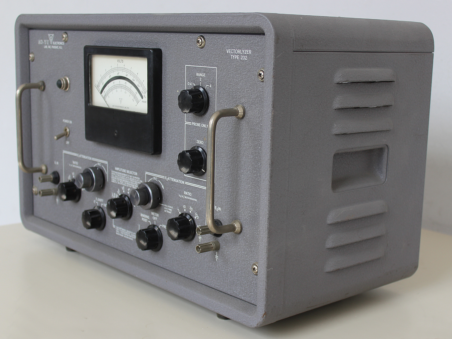
 Vectorlyzer Type 202 AD-YU Electronics Lab. Inc. Passaic, N. J. . Prima parte.
Nell’inventario D del 1956, in data 28 maggio 1963, al n° 3285 si legge: “Ing. Mario Vianello – Milano. Vectorlyzer. Dest. Elettronica. ₤ 710.000” .
Il prof. Luigi Silenzi ricorda di averlo usato, ma alcuni di noi allievi dell’epoca non ne hanno memoria, forse perché è uno strumento per applicazioni veramente complesse che esulavano dai programmi di insegnamento.
Abbiamo trovato negli archivi della Sezione Elettronica il manuale delle istruzioni originali risalente al marzo del 1961; in fondo al manuale vi sono due pagine, datate rispettivamente 18/05/1962 e 31/05/1962, dei collaudi a cui è stato sottoposto questo strumento. Dette pagine sono nella quarta parte.
Invece di trascrivere una traduzione affrettata, ed anche per mantenere l’efficacia dell’originale, ne riportiamo alcune parti in inglese.
§§§§§§§§§§
DESCRIPTION
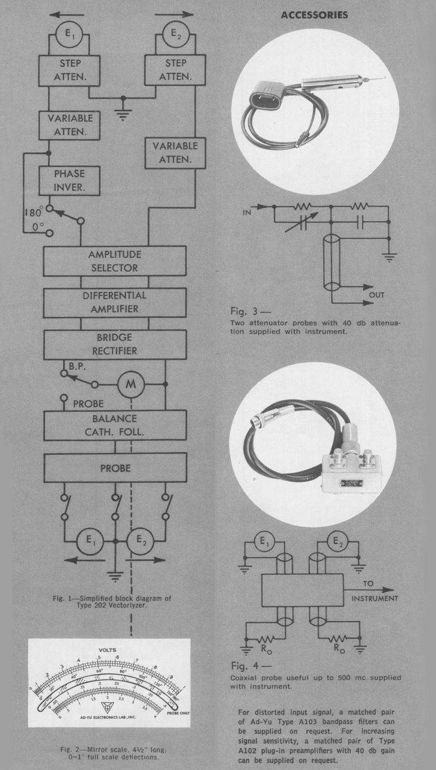
This instrument makes possible for the first time a number of measurements which were formerly impossible, or at best very difficult to accomplish by other means. For example, it can be used to measure very small phase angles (such as a fraction of 1°) with a maximum error of less than 0.02° or 2% when using the range of 1° full scale. The operating principle of this instrument is based on measuring vector difference of two input voltages, which permits unusual speed and accuracy for measuring vector relations of alternating voltages. Type 202 is essentially a combination of the following elements: Two step attenuators, two continuously adjustable attenuators, a wide-band phase inverter, an amplitude selector, a degenerative vector difference amplifier, a bridge rectifier, a balanced cathode follower, a high frequency probe, and a regulated power supply. These elements, except the regulated power supply, are arranged as shown in the block diagram of Fig. 1.
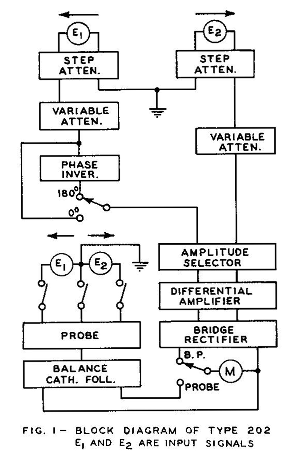
The high frequency probe consists of a differential rectifier of which the natural resonant frequency is made very high (above 1000 mc). The differential rectifier is a special type of peak rectifier circuit which is capable of producing a direct current potential at its output terminals proportional to the vector difference between the two voltages applied to Its Input terminals. Let E1 and E2; be the two input signals and θ be their phase difference. When their amplitudes are made equal to | E’1 | and | E’2 | respectively by adjusting the built-in attenuators, the meter reading E0 may be expressed in terms of phase angle θ as(1) E0 = E’2 – E’1 = | E’1 | (cos θ + j sin θ — 1)
When | E’1 | = | E’2 |
Then we have
(2) | E0 | = | E’1 | (cos θ —1)2 + sin2 θ = | E’1 | sin (θ /2)
By arranging terms
(3) | E’1 | / | E0 | = 1/ [2 (sin θ/2)]
Thus the output meter may be calibrated to indicate phase angle in degrees between two voltages. For instance, when | E’1 | is made equal to the half-scale reading during adjustment of attenuators, the meter will read 60 degrees at its center, 0 degree at zero and 180 degrees at full scale. By substituting θ = 2° in Equation (3), we may find | E’1 | / | E0 | = 28.65
Therefore, by applying signal amplitude | E’1 | equals 28.65 times the voltage amplitude for full scale deflection, the meter will read 2° at full scale.
USES
MEASURING VERY SMALL PHASE ANGLE FROM 15 CPS TO 50 KC.
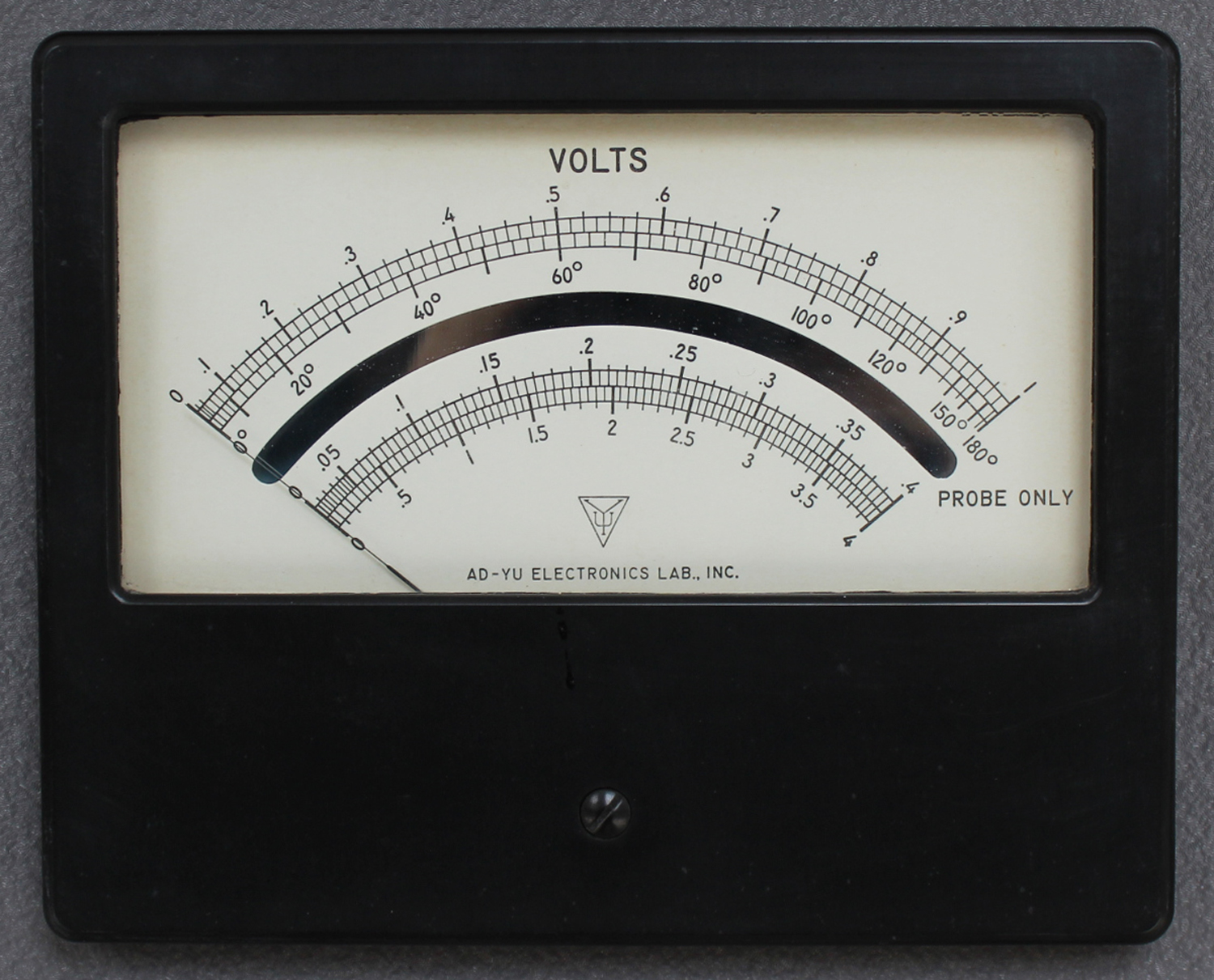
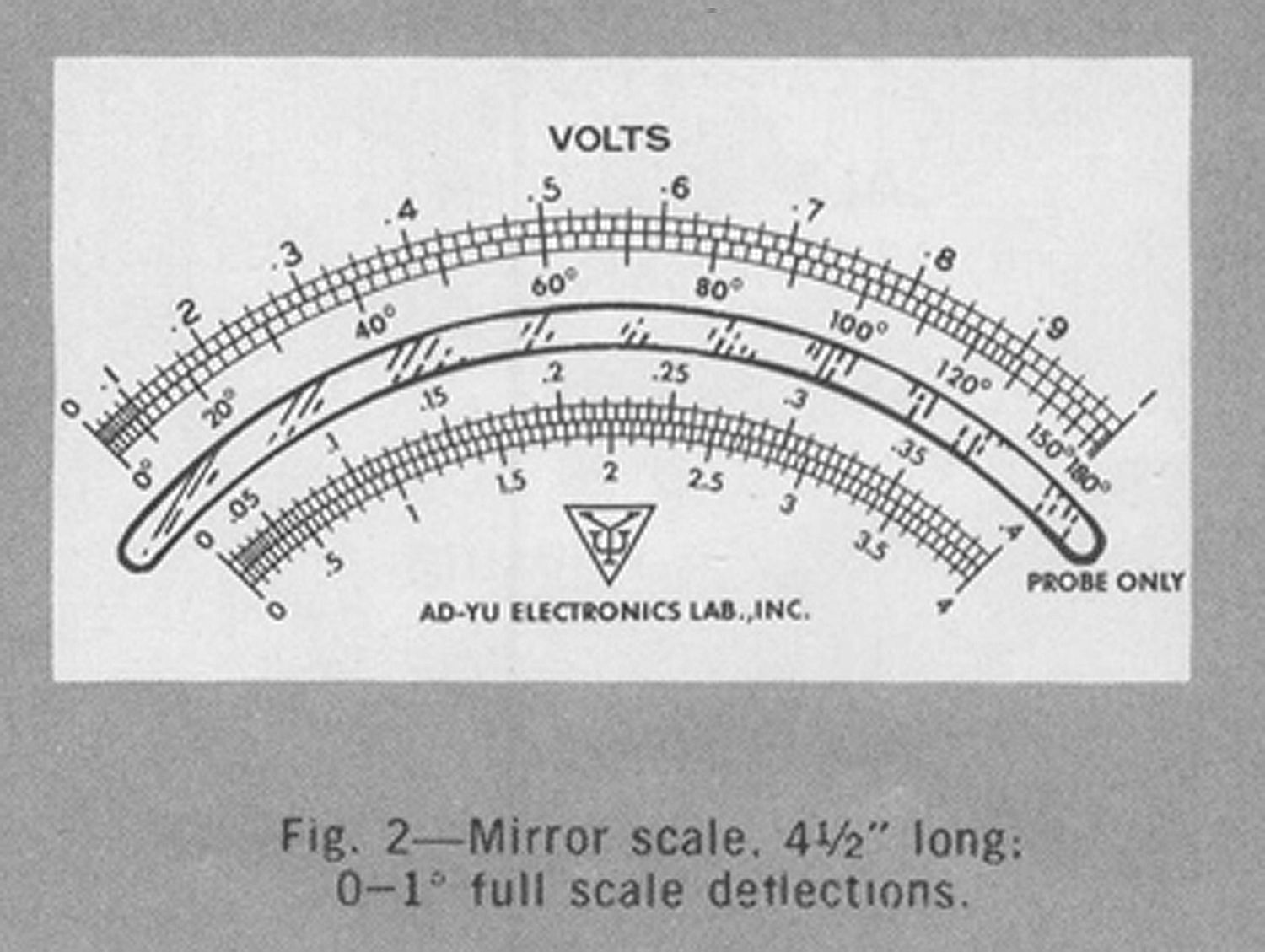
The instrument provides full scale deflection of 1°, 2°, 4°, 10′ and 20°. The scale of these phase ranges is 41/2 inches long and has 100 divisions total, top scale in Fig. 2. Phase deflection as small as 0.005° (18 seconds) will produce movement of half division on the 1° range.
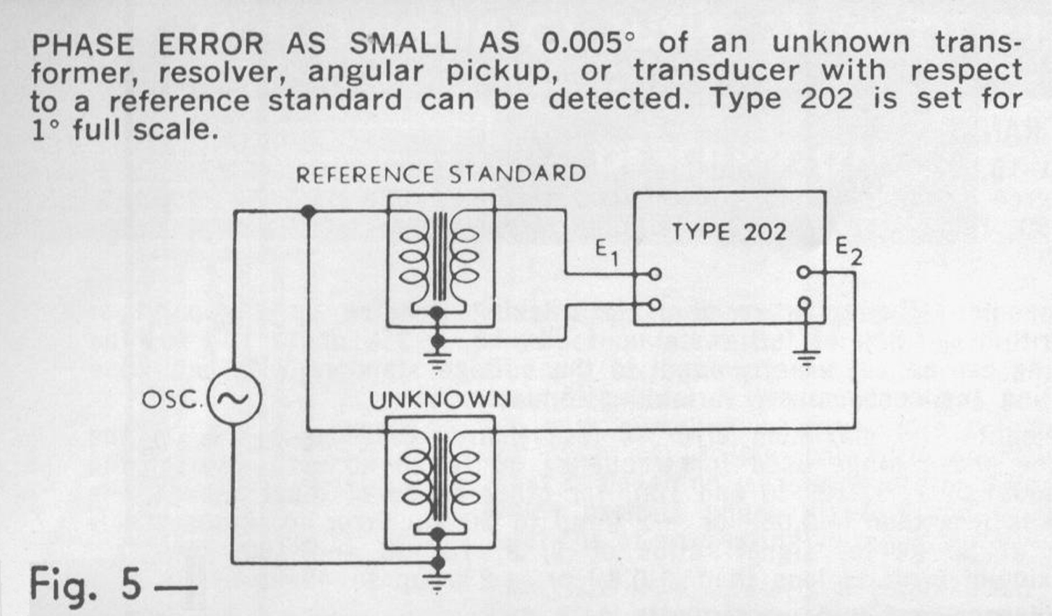
 MEASURING PHASE ERROR BETWEEN AN UNKNOWN COMPONENT AND A STANDARD COMPONENT. Deviation as small as 0.005° can be detected by using the 1° phase range of the instrument. Phase error over a wide frequency range can easily be measured simply by changing the signal frequency. since the instrument is a wide-band device.
MEASURING VOLTAGE ACROSS TWO POINTS WHICH ARE BOTH ABOVE GROUND POTENTIAL. Vector difference of two alternating voltages can be read directly on the panel meter, since the instrument is basically a vector difference voltmeter. A 180° phase inverter is provided in one channel in order to convert the instrument into a vector sum voltmeter.
MEASURING VECTOR RELATIONS UP TO 500 MEGACYCLES. An r.f. probe is provided for reading vector difference of two voltages up to 500 mc directly on the panel meter. When the amplitudes of two input signals and their vector difference are known, phase angle as well as vector sum can be easily determined.
SPECIFICATIONS
20 CPS TO 40 KC INPUT TO BINDING POST
PHASE ANGLE RANGE:
0-1, 0-2, 0-4, 0-10, 0-20 and 0-180 degrees. A panel switch is provided for inserting 180-degree phase shift to convert above ranges into 180-181, 180-182, 180-184, 180-190, 180-200, and 180-360 degrees respectively.
ACCURACY:
Voltage Measurement — The accuracy of scale tracking (reading on any point of the scale) is within ±1.5% of full scale up to 40 kc, ±2% up to 100 kc. The full scale reading can be set exactly equal to the voltage standard with negligible error by adjusting the continuously variable attenuator.
Phase Measurement—The maximum error is less than ±0.02° or ±2% of the full scale of the phase range used for frequency up to 20 kc with ratio of the input signals equal to 1, 3, 10, 30 and 100; for other ratios of input signals, the maximum error is less than ±0.06° or ±2% up to 20 kc. Error increases slowly up to ±0.03° at 50 kc for signal ratios of 1, 3, 10, 30 and 100; for other ratios, the maximum error is less than ±0.8° or ±2% up to 40 kc.
FREQUENCY RANGE: (SEE ACCURACY)
INPUT IMPEDANCE:
20 μμf shunted by 1 megohm at binding post terminals; 5 μμf shunted by 1 megaohm at the input terminal of the 40 db attenuator probe.
VOLTAGE RANGE:
The maximum voltage sensitivity for full scale deflection is 0.007 volt rms or better. With variable attenuator at calibrated position (marked “.01 v rms”), direct reading on panel meter in volts rms full scale is 0.01 at “Ratio 1” position. Step attenuator with ratios of 3, 10, 30 and 100 gives 4 additional ranges, 0.03, 0.1, 0.3 and 1 volt full scale. With plug-in probe attenuator (100 to 1 attenuation), it gives 5 additional ranges, 1, 3, 10, 30 and 100 volts full scale.
MINIMUM SIGNAL AMPLITUDE FOR PHASE MEASUREMENT:
For phase range of 1° full scale, the minimum amplitude for both input signals is required to be 0.4 v rms; for 2° full scale, 0.2 v rms is required; 4°-0.1 v rms; 10°-0.04 v rms; 20°-0.02 v rms; 180°-0.004 v rms.
MAXIMUM SIGNAL AMPLITUDE FOR PHASE MEASUREMENT:
Signal amplitude up to 100 volts can be applied to the instrument for phase measurement by means of the continuously adjustable attenuators, step attenuators, and plug-in probe attenuators having 100 to 1 ratio supplied with the instrument.
STABILITY OF PHASE MEASUREMENT:
The stability of phase reading depends primarily on the stability of input signalamplitudes. Since the instrument is based on measuring vector difference of two input signals, phase reading will be stable when both input signals have constant amplitudes, otherwise will vary proportionately with signal amplitudes.
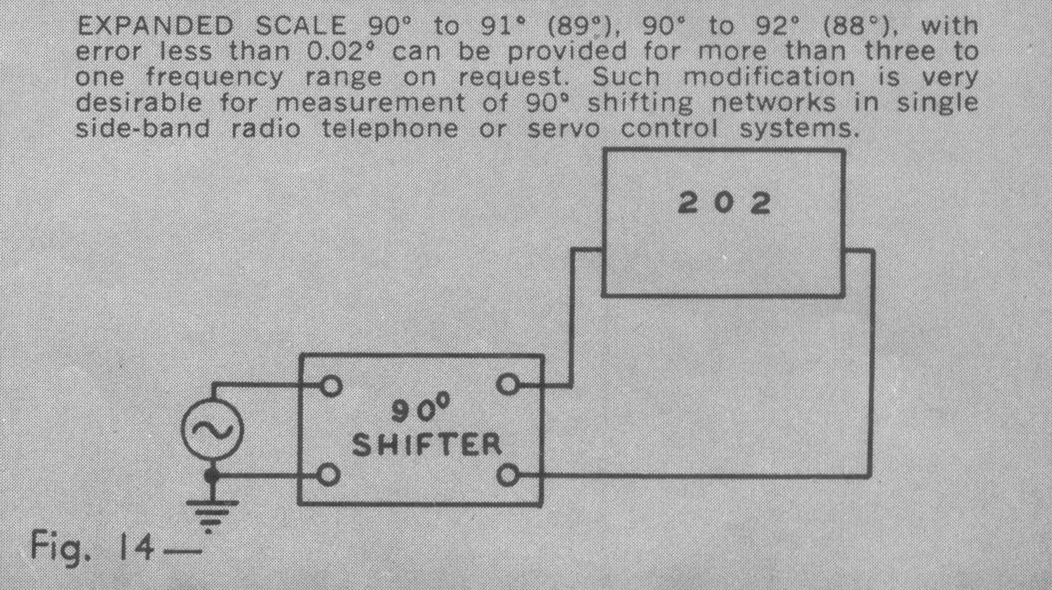
EXPANDED SCALE:
For accurate measurement of phase angle between 0 to 360°, an expanded scale may be provided on request at a moderate extra charge. For example, scales from 90° to 91°(89°), 90° to 92°(88°), 90° to 94°(86°) with accuracy of ±0.02° may be obtained for approximately 3 to 1 frequency range with frequency center
specified on order.
ATTENUATORS:
Two identical continuously adjustable attenuators are provided with one in each channel. The attenuation ratio is approximately 4 to 1. Two identical step attenuators are also provided, one in each channel, having steps of 1, 3, 10, 30 and 100.
The accuracy of attenuation can be made almost exact by adjusting the continuously variable attenuator; otherwise, the accuracy of attenuation is ±3%. in addition, two plug-in-probe attenuators having 100 to 1 ratios ±3% are provided for extending the attenuation range of the step attenuator.
WAVEFORM DISTORTION:
Harmonics and noise will affect the accuracy of phase measurement unless they are identical for both signals. Otherwise, a matched pair of Ad-Yu A103 bandpass filters should be used, with one in each channel. For voltage measurement, the instrument measures the rms value of both the fundamental component as well as harmonics and noise.
40 KC TO 500 MC — INPUT TO PROBE
ACCURACY:
±3% below 100 mc [Mc N.d.R.], increasing slowly up to ±5% at 500 mc [Mc N.d.R.] for both voltage and phase measurements.
FREQUENCY RANGE:
100 kc to 500 megacycles.
INPUT IMPEDANCE:
2.5 μμf shunted by 100,000 ohms; coaxial arrangement with BNC connectors for matching low impedance cable and terminating resistors, or jack input with 2.5 μμf and 100 k can be supplied on request.
VOLTAGE RANGE:
0.4, 2 and 4 volts rms full scale.
MINIMUM VOLTAGE FOR PHASE MEASUREMENT:
0.2V for 0-180°; higher voltage required for more sensitive range.
PHASE MEASUREMENT:
Direct reading in degree only with equal input signals; with triangle method calculator, or curves otherwise.
INPUT POWER:
60 watts at 115 volts rms ±10% 50/60 cycles (230 volts available on request).
STABILITY:
Meter indication changes 0.1% or less for 10% variation of line voltage.
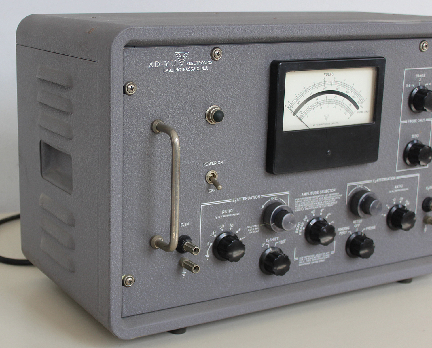
PHYSICAL SIZE:
Panel—l9″ × 10½” with mounting slots for all standard racks. Chassis — 17” × 8¼” × 4″ Cabinet 12″ × 10″× 20½”; 16 gauge steel light gray wrinkle finish, round corners
PRICE:
$ 588.00 F.0.B. Passaic, N. J. Delivery normally 1-2 weeks.
March 1961 Made in U.S.A.»
§§§§§§§§§§
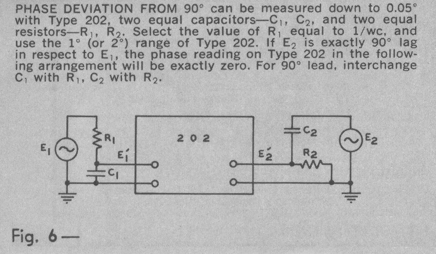
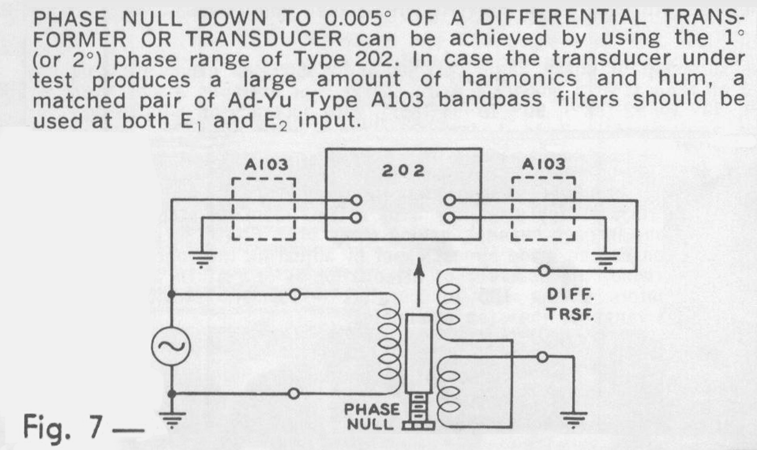
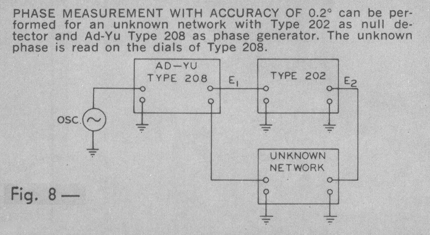
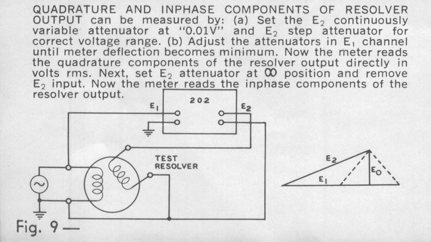
Oltre alle figure 1 e 2 citate nel testo del manuale riportiamo le figure 3 e 4 degli accessori e di seguito le figure da 5 a 14 delle applicazioni suggerite, opportunamente ingrandite.
Per consultare le altre schede scrivere “Vectorlyzer” su Cerca.
Foto di Claudio Profumieri, elaborazioni e ricerche di Fabio Panfili.
Per ingrandire le immagini cliccare su di esse col tasto destro del mouse e scegliere tra le opzioni.