 Precision Phase Meter Type 405L AD-YU Electronics Lab. Inc. Passaic. N. J. Seconda parte.
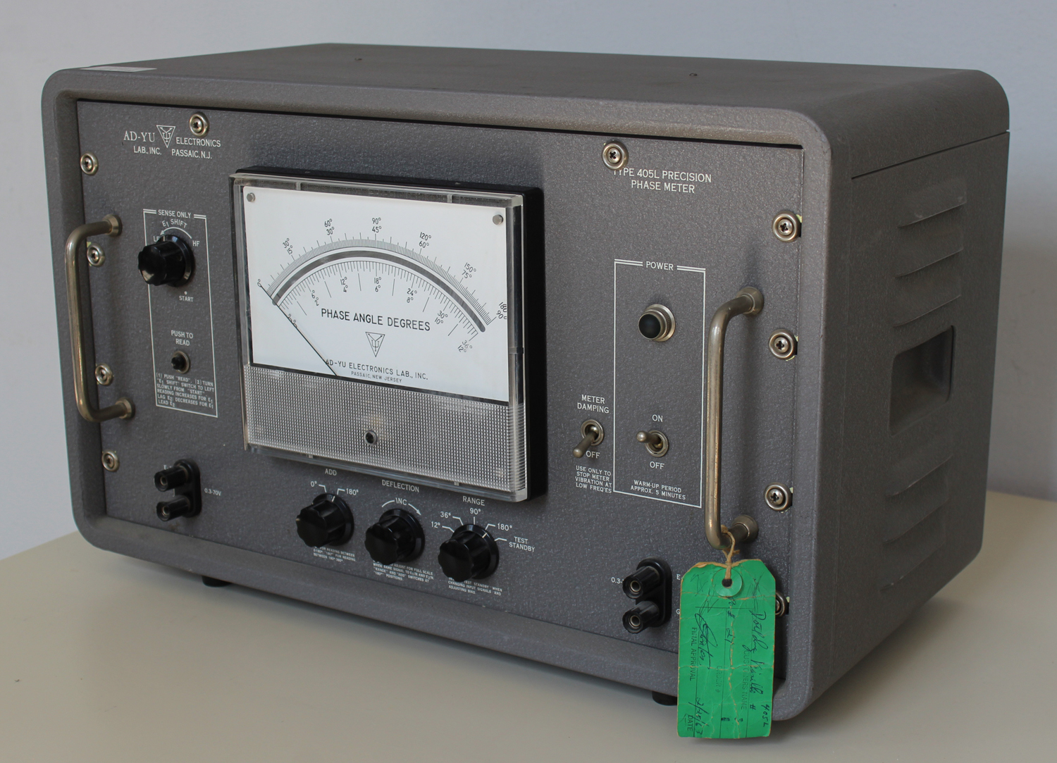
Nel cartellino verde visibile in diverse foto vi è la data “2/20/63” almeno così pare di leggere, cioè 20 febbraio 1963.
Nell’inventario D del 1956, in data 28 maggio 1963, al n° 3284 si legge: “Ing. Mario Vianello – Milano. Misuratore di fase. Dest. Elettronica”.
Abbiamo così una conferma dell’anno di acquisto dello strumento.
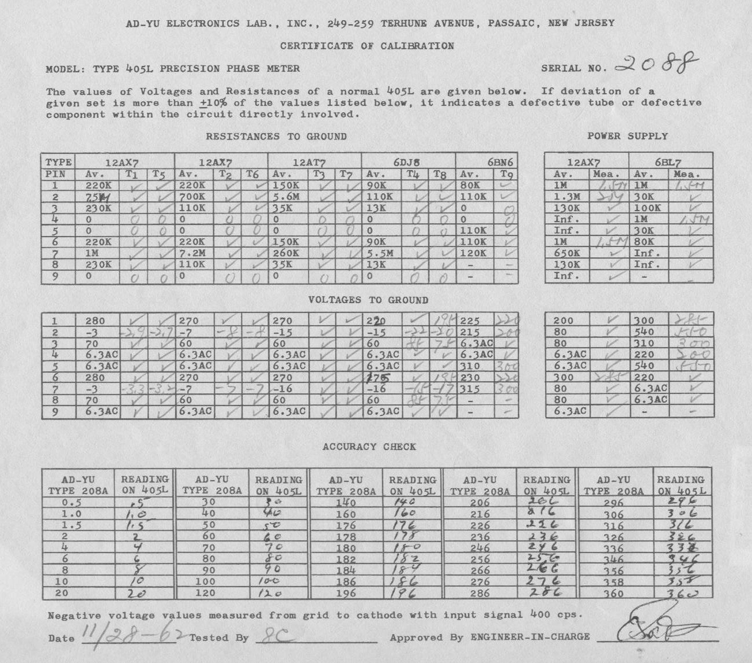
Nel collaudo eseguito dalla ditta si legge la data: 28 novembre 1962.
Nella Sezione Elettronica sono conservati due manuali di istruzioni con un allegato dattiloscritto che riguardano questo strumento.
Riportiamo qui di seguito il testo dattiloscritto.
§§§
«Operating Instructions
For Type 405 Series Precision Phase Meter
COMPLETE CIRCUIT DIAGRAM:
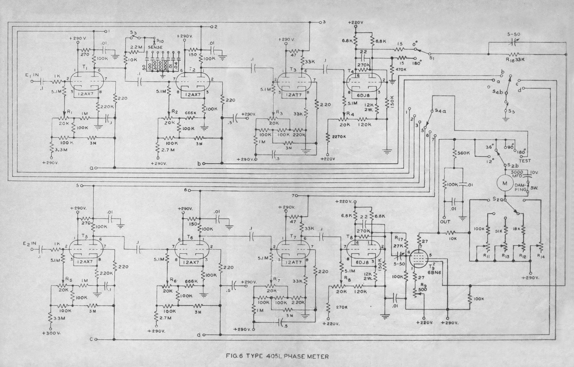
Fig. 6 shows a complete circuit diagram of the instrument, Tubes T1 to T4 are connected as a four-stage cathode-coupled limiter for E1 channel. Similarly, T5 to T8 are for E2 channel. A gated beam tube, T9, is used as a coincident slicer. The panel meter is activated by the plate current of T9. When switch S2 is on “TEST” position, the panel meter indicates the plate current of the output section of any limiter stage, T1, T2, T3, T5, T6, or T7, also T4 and T8 in 405H, depending on the position of S4a. The bias voltage of any one of the eight limiter stages can be so adjusted as to maintain a constant plate current equal to the quiescent value, when the grid is excited by a symmetrical signal of which the amplitude varies from zero to the maximum permissible value. When any stage is so adjusted, its square wave output will be symmetrical provided that the amplitude of the input signal is never large enough to cause the tube to draw grid current.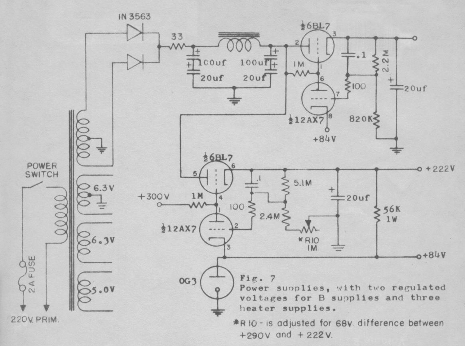 Fig. 7 shows a circuit diagram of the power supplies, which yield two
regulated B+ voltages and the heater voltages.
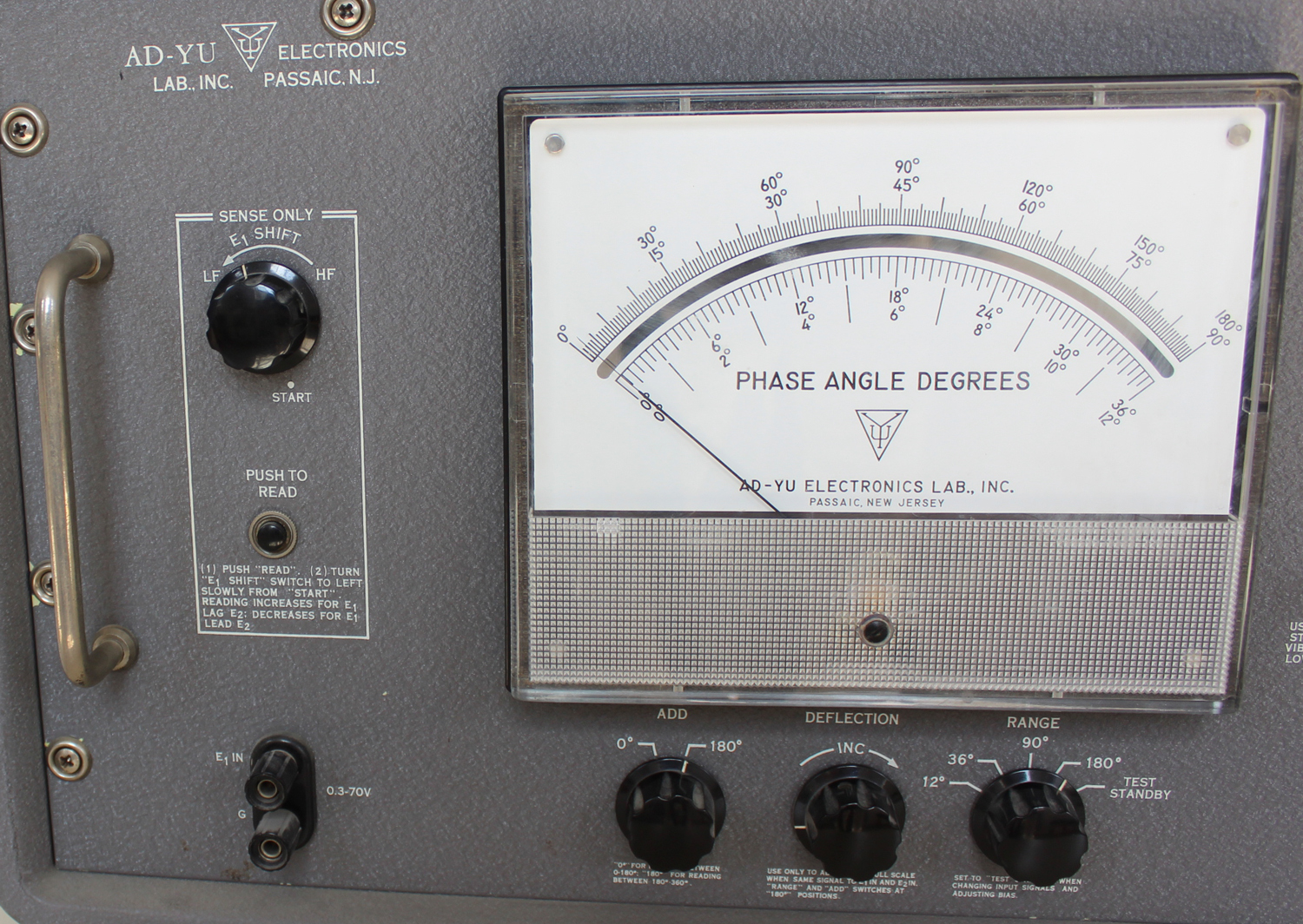
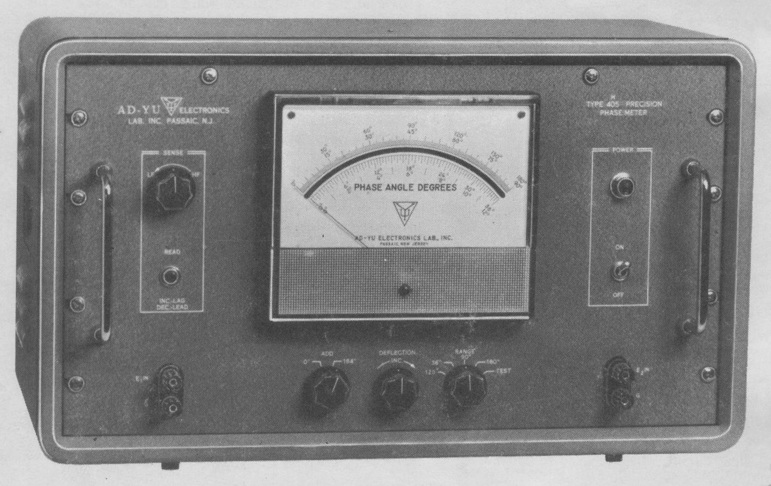
DESCRIPTION OF CONTROLS AT THE FRONT PANEL
1.“E1 IN”, binding post – Provides a connection of the input signal to
E1 channel.
2.“ADD – 0° – 180°”, 1-pole, 2-position switch (S1 in Fig. 6). Add 180° to the meter reading at “180°” position, add nothing at “0°” position.
3.“DEFLECTION INC.”, potentiometer, 500-ohm (R9 in Fig. 6), Used for adjusting the meter reading to 180° when both input channels are fed by an identical signal and “ADD” switch at “180°”.
4.“RANGE”, 2-pole, 5-position switch (S2 in Fig. 6) .To select the sensitivity of the panel meter, 12°, 36°, 90°, or 180° full scale for 405 and 405L; 36°, 90°, 120° or 180° for 405H. In addition, it connects the meter to anyone of the output plate circuits of the cathode-coupled limiters at “TEST” position. This position is used for adjusting the bias voltage of the limiter in order to give a symmetrical output square wave.
5.“POWER ON”, a toggle switch – to turn on and off the line voltage.
6.“E2 IN” – Provides connection of an input signal to E2 channel.
7.“SENSE LP-HF”, 1-pole, 8-position switch (S10 in Fig. 6) – Used to change the amount of phase lag at the plate of T1 for SENSE identification, i.e. determining the relative lag or lead of E1 with respect to E2.
8.“READ”, a momentary push-on switch (S3 in Fig. 6) – For connection of a shunting capacitance at the plate of T1 in order to introduce a lagging phase angle to the same channel for SENSE identification.
DESCRIPTION OF CONTROLS AT THE REAR OF CHASSIS:
1.“STAGE”, 3-pole, 8-position switch (S4 in Fig. 6), – For connecting the panel meter (when the “RANGE” switch is set at “TEST”) to the output plate circuit of one of the limiters, T1 to T3, T5 to T7, including T4 and T8 in 405H, and the input grid leak of the preceding limiter to push-button switch S5.
2.“GR”, push-button switch (S5 in Fig. 6) – For connecting the input grid leak of one of the limiters to ground in order to cut off the plate current and permit no signal feeding into the next stages
3.R11 for calibration of the 180° range.
4.R13 for calibration of the 90° range.
5.R12 for calibration of the 360° range.
6.R14 for calibration of the 12° (120° for 405H) range.
7.“OUT”, jack for connection to external recorder, quiescent potential at 300V ±10% for 405 and 405L, +280V for 405H.
8.“+300V”, jack at +300V ±10% B+ potential for 405 and 405L, +280V ±10% for 405H.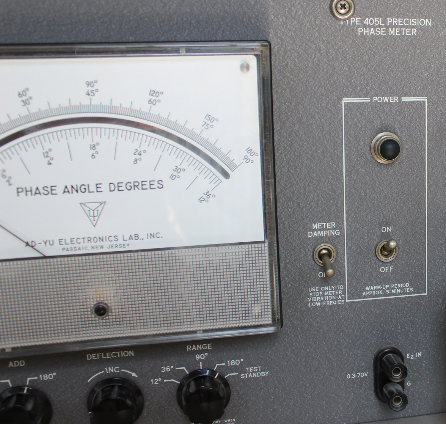 OPERATING PROCEDURE:
1.Plug the line cord into 220 volts, 50/60 cycles, (220 volts available on request)
2.Apply a single signal to “E1 IN” and “E2 IN” simultaneously, (This signal should lie between 0.3 volt and 70 volts for models 405 and 405L, or 2 volts and 40 volts for model 405H)
3.Set “ADD” switch to 180° position, and adjust potentiometer for 180°
reading on panel meter. Now turn the “ADD” to 0° position and the instrument is ready for use.
4.Apply the two signals of which the phase difference is to be determined to “E1 IN” and “E2 IN” and read the phase difference on the panel meter.
5.To identify the “SENSE” of the meter reading, turn “SENSE LF-HF” control to “START” extreme clockwise position; push in the “READ” switch; then turn the “LF-HF” control slowly counterclockwise until the meter reading starts to change. If the reading starts to decrease, E1 leads E2; if the reading starts to increase, E1 lags E2.
6.There are two methods for use with an external recorder: (1) For d.c. coupling, connect the recorder (which must have both input leads isolated from ground) to the jack “OUT” at the rear of the chassis. The quiescent potential of this jack is +300 ±10% for 405 and 405L, +280 ±10% for 405H. An R-C integrating circuit with time constant of .005
second is installed internally at this jack. The output voltage referring to B+ is zero for 0°, increases linearly to -14 volts for 405 and 405L, -4 volts for 405H, as measured at the plate of 6BN6.
(2) If the signal frequency is above 60 cps, a capacitor can be used for coupling and for isolating the B+ potential, In this case, connect a capacitor, about 0.5 μf, to the lead for the negative terminal of the meter and disconnect the panel meter from the circuit, and set “RANGE” switch to “180°” position.
BIAS ADJUSTMENT:
Bias controls R1 to R8, on top of the chassis, should be adjusted if meter reading varies with change of signal amplitudes or is off zero when a single signal is applied to both inputs, or when tubes are changed in the limiter stages. The procedure for adjusting the bias control, R1, for the limiter stage, T1 is as follows:
1.Apply a single signal (about 200 cps, 10 volts or more, symmetrical with respect to the zero axis) to both “E1 IN” and “E2 IN”.
2.Set the “RANGE” switch to “TEST” and the “STAGE” switch at rear to T1.
Take reading on meter.
3.Remove the input signal and short the input binding post to ground.
Take meter reading again.
4.Adjust R1 until the meter reading of step 3 equals that of step 2. Repeat the above steps several times to insure that the output plate current of T1 remains unchanged when the input signal varies from zero to over 10 volts.
The procedure for adjusting R2 for the second limiter stage, T2, is the same as described above, with the following exceptions: In step 2, set the “STAGE” switch to T2; in step 3, push the “GR” switch and remove the input signal. Use a similar procedure to adjust R3. The procedure for adjusting R5 is similar to that of R1. The procedure for adjusting R6, R7, is similar to that of R2 and R3. The order of adjustment must b from first to the second, to the third, to the fourth stage. This will insure that the input to the stage under adjustment (namely, the output of the previous stage) is a signal symmetrical with respect to the zero axis.
In 405H, the procedure for adjusting R4 and R8 is a similar to that of R3.
In 405 and 405L, the procedure for adjusting R4 is as follows: (a) Connect an oscilloscope to the output plate of T4, which can be reached without taking the cabinet off by pulling 6BN6, T9, out from its socket, then insert a wire to pin #2 for adjusting R4, pin #6 for adjusting R8. (b) Apply a sine wave signal about 5 volts with frequency at 100 kc to 200 kc to E1 IN binding post. (c) Adjust R4 until the output square wave at the plate of T4 becomes symmetrical with input signal varying from 1 volt over 10 volts. Fig. 9 shows that the waveform is symmetrical when a1 = a2 and b1 = b2. The procedure for adjusting R8 is the same as R4.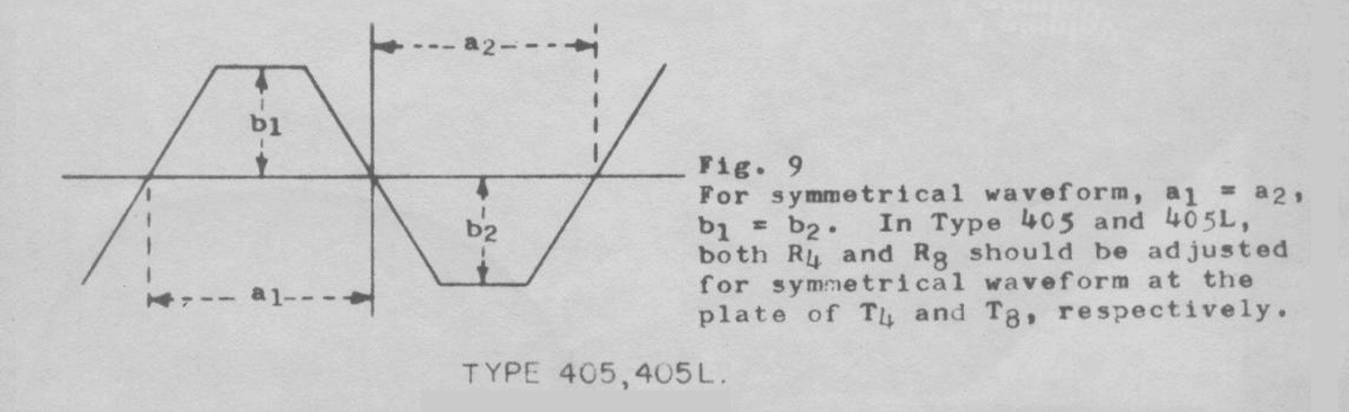 MAINTENANCE:
NOTE: When any one of the tubes, T1 through T8, is changed, the bias potentiometer of that tube must be adjusted according to the procedure, outlined in the previous section.
1.Defect – Meter reading changes with input signal amplitudes, and/or meter reading is not zero when a single signal is applied to both
“E1 IN” and “E2 IN”.
Cause – The bias voltages for one or more of the limiter stages has to be adjusted according to the described procedure. If the defect can not be eliminated after careful bias adjustment, it may be caused by one or more of the following causes: (a) Voltage across the grid leak, resistors (3 megaohms for 405 and 405H, 5.1 megaohms for 405L) is not zero: positive voltage due to leakage of coupling condenser or defective tube, negative voltage due to high output from previous stage or due to defective tubes of this stage or previous stage. (b) One or more of the limiter stages produces a round-top or round-bottom square wave due to defective tube (cut-off characteristics not identical between the two halves and also not sharp enough). This defect can be identified when the plate current indication on the panel meter varies with “RANGE” switch at “TEST” and input signal changes from a fraction of 1 volt to 20 or 30 volts. It also can be identified by using an oscilloscope to observe the output waveform with input signal just high enough to enable the starting of clipping. (c) Input signal is not symmetrical with respect to the zero axis. (d) A by-pass capacitor has excessive leakage in the first or second stage. This defect can be easily locate by using the following procedures: (1) Use a jumper to short the plate of T1 to the plate of T5. If the meter indication becomes zero, the difficulty is in the stage of T1 or T5. If the meter indication is still not zero, move the jumper to short the plate of T2 to the plate of T6. If meter indication becomes zero, the difficulty is in the stage of T2 or T6. Otherwise, move the jumper to T3 and T7. By using this procedure, the cause for off-zero may be located.
2.Defect – Meter reading drifts or fluctuates during bias adjustment and for phase measurement.
Cause – (a) Poor regulation from the power supply, check OG3, 12AX7, or 6BL7, (b) Potential across grid leak resistor is not zero, see 1 (a). (c) Check all d.c. potentials. (d) A by-pass capacitor has excessive leakage.
3.Defect – Meter reading is not zero when a single signal with high (or low) amplitude is applied to both input, and/or phase readings differ when two input signals interchange.
Cause – The tubes in the first stages (or second stages) of both channels have very different characteristics. This may be proven by inter-changing the tubes in the first stage (or second stage) of both channels.
If off zero at high signal, T5 is much weaker than T1; if off zero at low signal, T1 is much weaker than T5.
4.Defect – Meter reads off-scale or insufficient. “DEFLECTION INC.” control cannot bring it within range.
Cause – Potentiometer R11, located at the back of the chassis, has to be adjusted. This condition may also be due to a defective 6BN6 tube (T9).
5.Defect – Phase reading in 12° (120° for 405H), 36°, or 90° range is incorrect.
Cause – The 90°, 36°, and 12° ranges must be calibrated by means of potentiometers R13, R12, and R14, respectively. A circuit diagram for adjusting these potentiometers is given in Fig. 8. When frequency is 400 cps and C = 0.1 µf, the phase reading should be 10° for R = 702 ohms; 30° for R = 2.3 K; 70° for R = 10.93 K. The procedure is as follows;
(a) Hook up the circuit shown in Fig. 8. In this circuit, facility must be provided to vary either the resistor, R, or the oscillator frequency, F.
(b) With the “RANGE” switch at 180°, vary R or F until a phase shift of 70° is indicated on the panel meter.
(c) Using this setting of R and F, set “RANGE” switch at 90°, and adjust R13 until a reading of 70° is indicated on the panel meter.
(d) Adjust R or F for reading of 30° on the 90° scale.
(e) Using this setting of R and F, set “RANGE” switch at 36°, and adjust R12 until a reading of 30° is obtained on this scale.
(f) Adjust R or F for a reading of 10° on the 30° scale.
(g) Using this setting of R and F, set “RANGE” switch at 12°, and adjust R14 until a reading of 10° is obtained on this scale. In case that the range of R14 is insufficient to obtain 10° reading, adjust “DEFLECTION INC.” control to a different position which makes 10° reading on the panel meter possible by adjusting R14. Then set “RANGE” switch to 180° position, readjust R11 for correct meter reading. Repeat procedures (f) and (g) for 90° and 36° ranges.
6.Defect – The sum of the phase readings at “0°” and “180°” positions of the “ADD” switch not equal to 360°.
Cause – At low frequencies, such as 200 cps, the bias voltage for one or more of the limiter stages has to be adjusted. At high frequencies, it is due to the values of R16 and R17 being in-correct. It may also be due to defective panel meter.
7.Defect – D.C. grid bias on all stages fluctuates.
Cause – (a) Defect of regulating power supplies. (b) defective tube, coupling condenser, or by-pass condenser in the limiter stages.
8.Defect – The gain of corresponding stages (e.g., T1 to T5, T2 to T6, etc.) in channels E1 and E2 is not equal.
Cause – This may be due to unequal cathode or plate resistors in the corresponding stages, or defective tube.
9.Defect- The B+ potentials of the power supply read too high.
Cause – Filaments on the 12AX7 of the power supply are open.
10.Defect – Ripple on sine wave, and signal is not steady (in any stage). Cause – This may be due to 60-cycle pickup from heater to grid, or
heater to cathode leakage. Replace the tube of the faulty stage.
11.Defect – Insufficient deflection on the sensitive scale (0-12° for 405, 405L; 0-36° for 405R), all other ranges are satisfactory.
Cause – 6BN6 has insufficient emission, or adjustment of potentiometer R11 is incorrect, see Defect 5 (g).
12.Defect – Meter reading is not zero with a single input signal, phase reading stable by changing signal amplitudes and bias adjustment good.
Cause – Coupling capacitors, plate resistors, or cathode capacitors between two channels are not matched (should be matched within ±½% for all components used in the first and second stages). The method for locating the defect is given in 1 (e). If the reading is zero below 1 kc and not zero at higher frequencies, the location of various coupling capacitors should be adjusted.
13.Defect – Meter reading below zero with a single signal applied to both E1 IN and E2 IN.
Cause – Calibration potentiometer for the range in question has leakage to ground. Replace the potentiometer, or insulate the potentiometer from the chassis.
14.Defect Meter reading not equal for interchanging of input signals.
Cause – Signals have a large percentage of harmonics and noise, coupling resistors at input of 6BN6 are not correct, or incorrect bias Adjustment. It may also be due to too much stray capacitance to ground in one channel, add a trimmer in the other channel for balance.
CHECK ACCURACY OF PHASE READING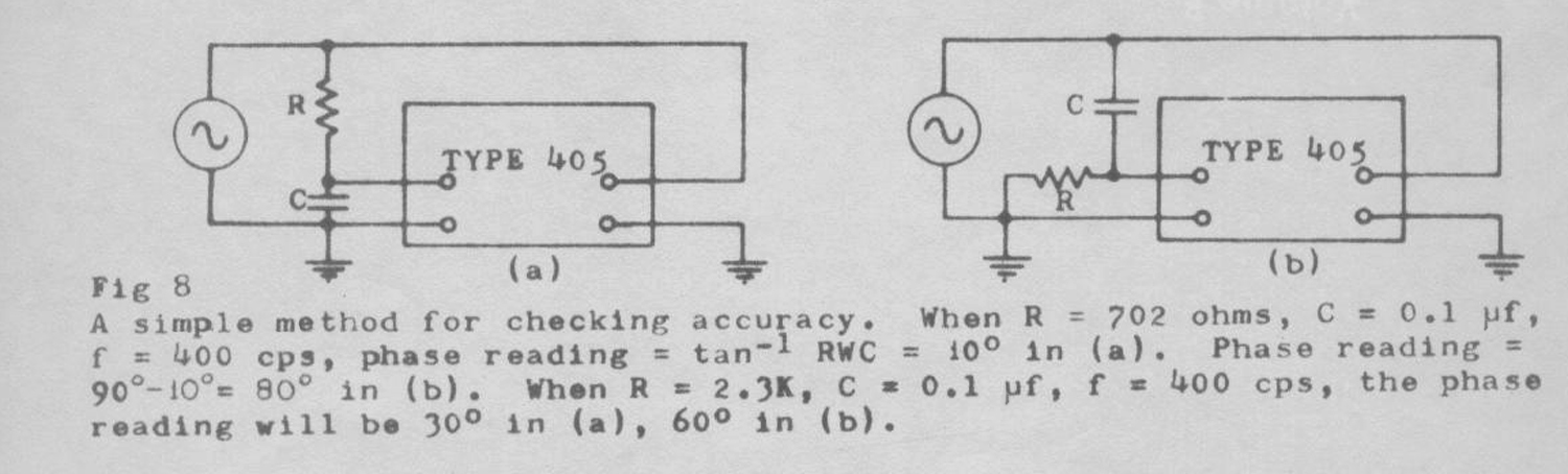 The accuracy of the instrument can be checked by reversing the connections of the resistor-capacitor combination of Fig. 8. When the frequency is 400 cps and the capacitance is 0.1 µf, the reading is 10° for R = 702 ohms; after interchanging the resistor with the capacitor, see Fig. 8b, the reading should be 80°. Caution: The amplitude of both inputs should be above the minimum signal requirement of the instrument, 0.3 volt for 405 and 405L; 2 volts for 405H. Therefore, the oscillator output should be above E min./cos θ. For example, when C = 0.1 μf, R = 702 ohms, the minimum oscillator voltage should be 2.5 volts for the arrangement given in Fig. 8a for 405H; 11.5 volts when R is interchanged with C for 405H. See Fig. 8b for R = 2.3K, the meter reading is 30°; after reversing, the reading should be 60°. For R = 10.93K, the reading is 70°; after reversing, the reading should be 20°.
D.C. VOLTAGES AND RESISTANCES: All d.c. potentials listed in the tables given below were measured with a vacuum tube voltmeter having 11 megaohms input resistance. A voltmeter having a different input resistance may register a different voltage, especially the d.c. potentials on the grids. Furthermore, the values may differ from one set to the other by ±10% or slightly more. Measurement of d.c. voltages and resistances often locates the source of the defect.
USE OF EXTERNAL RECORDER WITH TYPE 405
An analog output is derived from the plate of the 6BN6 coincident slicer and is connected to the jack labeled “OUT” at the rear of the instrument. The output pulses are integrated via an R-C network which produces a time constant of 0.005 seconds and a D.C. source impedance of approximately 700k. The output scale factor is 77.7 millivolts per degree of phase reading on the Type 405 and Type 405L; 22.2 millivolts per degree on the Type 405H. These scale factors apply only for recorder input impedances which are considerably higher than the analog voltage source impedance. It should also be noted that the reference voltage for the analog output, available at the other rear jack is +300v ±10% on the 405/405L and +280v ±10% on the 405H. This means that the recorder must be capable of off ground operation at the above stated voltages. The following sketch should further clarify the methods of driving extreme recorders. The choice of values of R and C depend on the signal frequency and the input impedance of the recorder. Higher value of R and C give better filtering but more attenuation of the signal applied to the recorder. In general R = 500k to 1 meg and C = 0.1 μfd to 0.5 μfd are sufficient for most applications except in cases where the signal frequency is below 60 cps. Here it is recommended that the value of C be increased to 1 or 2 μfd in order to achieve better filtering of ripple».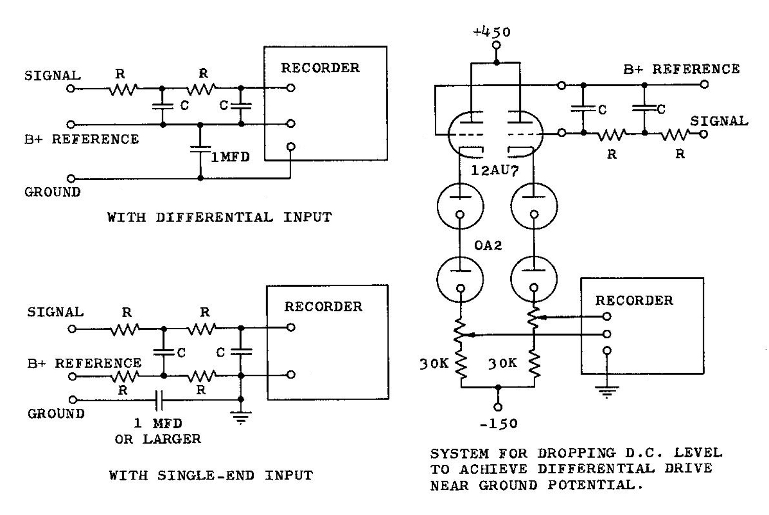
 §§§
§§§
Per consultare la prima parte scrivere “405L” su Cerca.
Foto di Claudio Profumieri, elaborazioni e ricerche di Fabio Panfili. Testo a cura di Fabio Panfili.
Per ingrandire le immagini cliccare su di esse col tasto destro del mouse e scegliere tra le opzioni.

Istituto Tecnico Tecnologico Montani