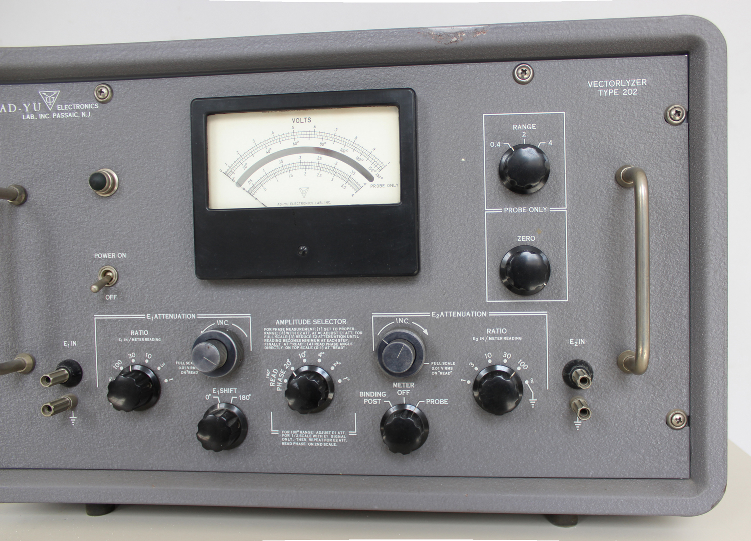
 Vectorlyzer Type 202 AD-YU Electronics Lab. Inc. Passaic, N. J. . Terza parte.
Nell’inventario D del 1956, in data 28 maggio 1963, al n° 3285 si legge: “Ing. Mario Vianello – Milano. Vectorlyzer. Dest. Elettronica. ₤ 710.000” .
Il prof. Luigi Silenzi ricorda di averlo usato, ma alcuni di noi allievi dell’epoca non ne hanno memoria, forse perché è uno strumento per applicazioni veramente complesse che esulavano dai programmi di insegnamento.
Abbiamo trovato negli archivi della Sezione Elettronica il manuale delle istruzioni originali risalente al marzo del 1961.
Invece di trascrivere una traduzione affrettata, ed anche per mantenere l’efficacia dell’originale, ne riportiamo alcune parti in inglese.
§§§§§§§§§
PREPARING THE INSTRUMENT FOR OPERATION:
1.Set “BINDING POST, METER OFF, PROBE” to “METER OFF” and both “ATTENUATION RATIO” switches to their respective “∞” ground positions.
2.Plug line cord into 115-volt (230 volts available on special order), 50-60 cycle supply and turn power on.
3.Select attenuation ratio suitable for both input signals.
4.For meter zero, use mechanical control-screw on the meter with S6 at “METER OFF” when binding posts are used, or the “METER ZERO” control when the probe is used.
5.Set “AMPLITUDE SELECTOR” switch to “READ” position for all measurements except when measuring small phase angles.
MEASURING VECTOR DIFFERENCE OF TWO UNKNOWN VOLTAGES:
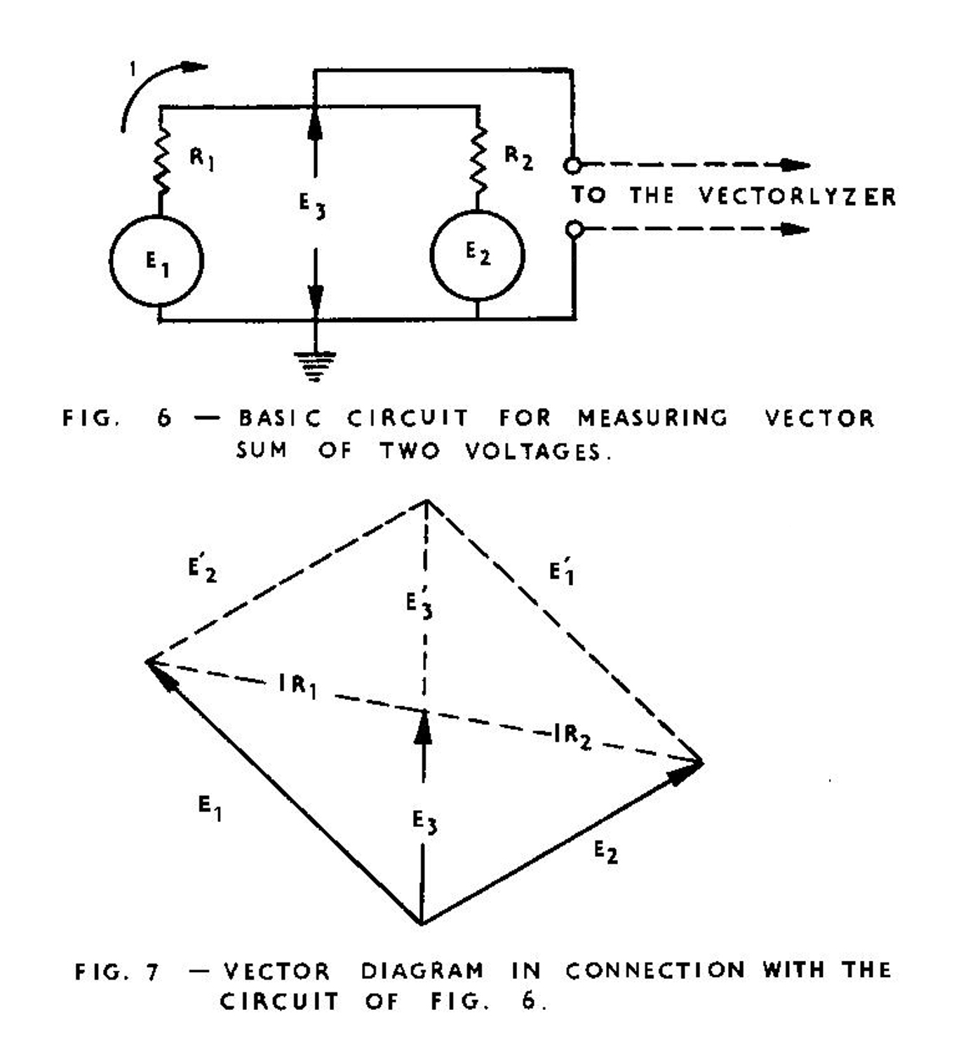
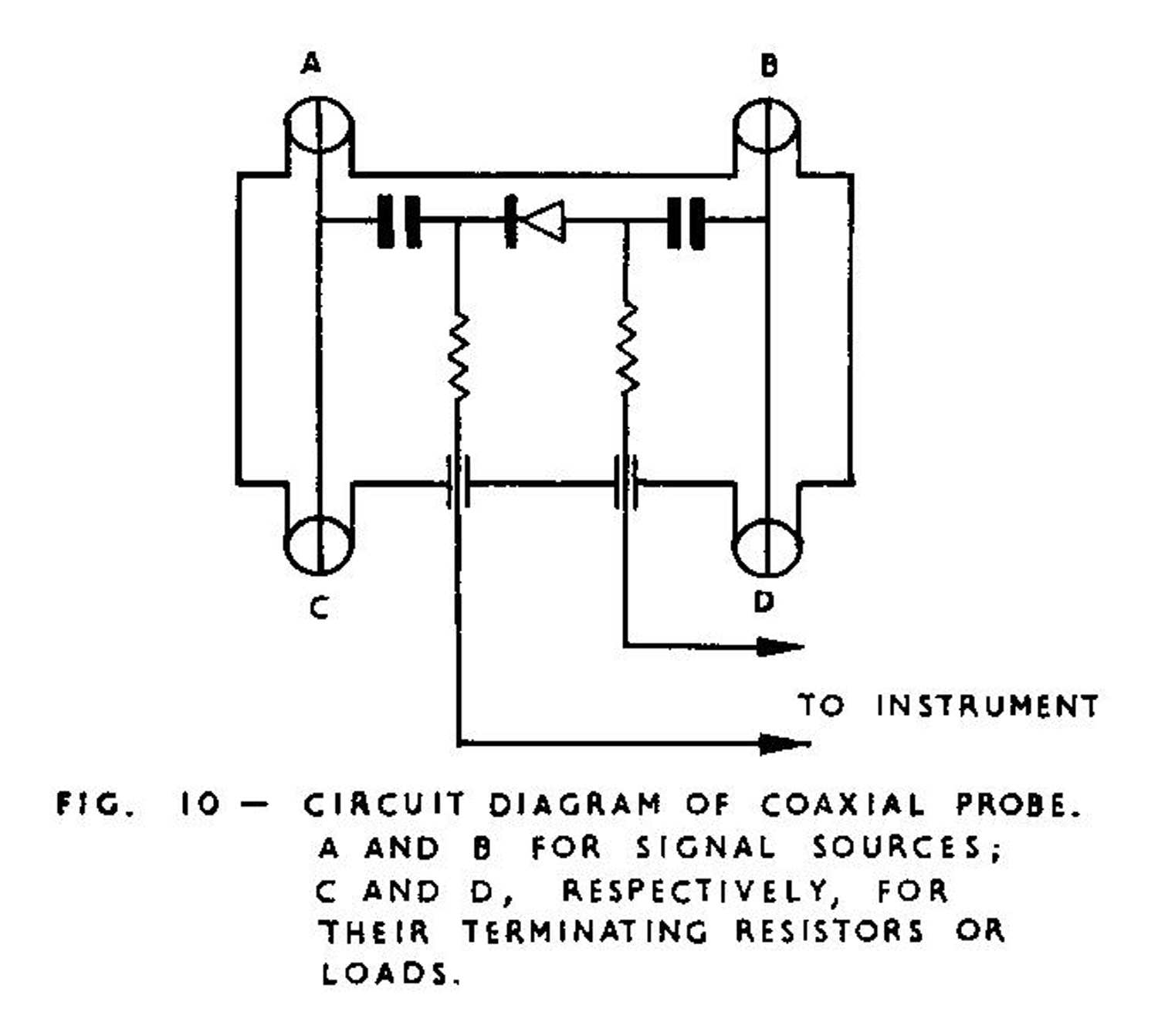
Since the two input terminals of a differential amplifier or rectifier can be connected to points which are both above a.c. ground potential,the vectorlyzer becomes a simple and convenient device for determining the vector difference of two voltages. For operation at high frequencies, 100 kc to 500 mc (Mc N.d.R.), connect the two unknown voltages to the two connectors at one side of the probe, and terminate their characteristic impedance at the other side, see Fig. 10.
The output meter will read directly the vector difference of the two unknown voltages. For operation at low frequencies, 20 cps to 100 kc, the procedure is as follows:
1.Set “BINDING POST, METER OFF, PROBE” switch to “BINDING POST”.
2.Set both “E1 ATTENUATION RATIO” and “E2 ATTENUATION RATIO” switches to a position having equal attenuation and its full scale reading higher than the amplitude of the larger signal.
3.Set “AMPLITUDE SELECTOR” control to “READ” position, set “E1 ATTENUATION INC.” and “E2 ATTENUATION INC.” at “0.01” position.
4.Apply both signals simultaneously and take meter reading. The answer is the product of the reading on the panel meter multiplied by the ratio indicated on the dial of “E1 ATTENUATION RATIO”
USING THE VECTORLYZER AS A SIMPLE VOLTMETER:
For frequencies above 100 kc, it is recommended to apply the signal to one connector of the probe and ground the other connector of the same side. For frequencies below 100 kc, it is recommended to turn “E2 ATTENUATION RATIO” switch to ground, set “E1 ATTENUATION INC.” at “0.01”, “E1 ATTENUATION RATIO” at a position which provides sufficient attenuation in order not to overload the panel meter, and apply input, signal only to “E1 INPUT” binding post. The amplitude of input signal equals the ratio at “E1 ATTENUATION RATIO” times the meter reading.
OPERATING PRINCIPLES OF MEASURING PHASE ANGLE WITH 0-180° SCALE, 20 CPS TO 100 KC:
In Fig. 8, E1 and E2 are two unknown voltages, and the arrows indicate their polarities. If the amplitudes of E1 and E2 are made equal by adjusting the attenuators, the meter reading E0 may be expressed in terms of phase angle θ as
(1) E0 = E2’ – E1’ =|E1| (cos θ + j sin θ – 1),
then we have
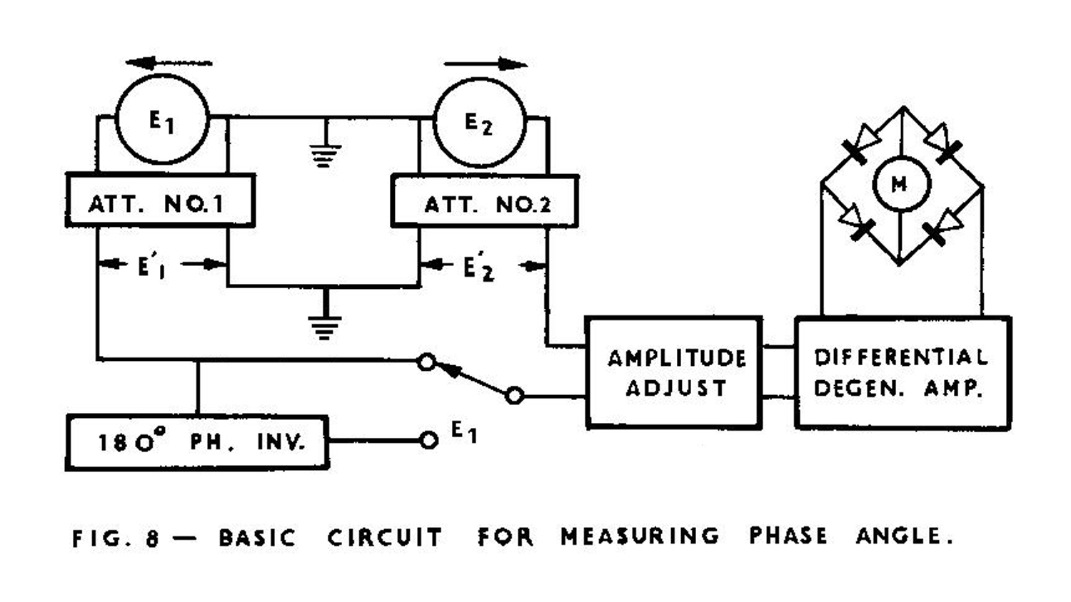 (2) |E0|=|E1| √ [(cos θ -1)2 + sin2 θ] = 2 |E1| sin (θ /2)
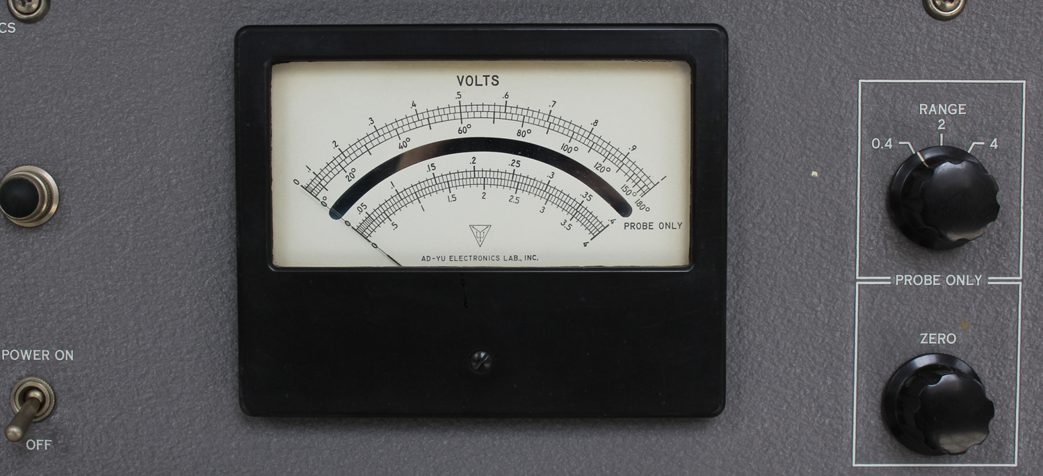
Thus the output meter may be calibrated to indicate phase angle in degrees between two voltages. For instance, when E1 is made equal to the half-scale reading (0.5 v) during adjustment of attenuators, the meter will read 60° at its center, 0° at zero and 180° at full scale. In case that the phase angle between two voltages under consideration is nearly equal to 180°, the accuracy of reading can be greatly increased by introducing a phase shift of 180° in E1 channel. After inserting 180°, a second scale starting with 180° at its position is then established.
PROCEDURE FOR USING 0-180° FULL SCALE:
1.Turn “AMPLITUDE SELECTOR” switch to “READ” position.
2.Apply E1 to “E1 IN” binding post, set “E1 ATTENUATION RATIO” to a position of which the full scale sensitivity is slightly larger than the amplitude of E1, and set “E2 ATTENUATION RATIO” to ground.
Then adjust “E1 ATTENUATION INC.” control until the pointer of the meter reaches the mid-point of the voltage scale, namely the mark “0.5” at the top scale.
3.Set “E1 ATTENUATION RATIO” to ground, and set “E2 ATTENUATION RATIO” to a position of which the full scale sensitivity is slightly larger than the amplitude of E1, apply E2 to “E2 IN” binding post, then adjust “E2 ATTENUATION INC.” control until the pointer of the meter again reaches the mid-point of the voltage scale.
4.Apply both E1 and E2 simultaneously, set both “ATTENUATION RATIO” switches for E1 and E2 to the positions used in (2) and (3) respectively, and read the phase angle directly on the “0-180°” scale, Add 180° to the meter reading when the selector for “E1 SHIFT 0-180°” is set at “180°” position.
OPERATING PRINCIPLE FOR MEASURING SMALL PHASE ANGLE, 20 CPS TO 100 KC:
Referring to Eq. (2), when the phase angle θ decreases, the magnitude of E0 may be held constant if the amplitudes of the input voltages increase accordingly. This in turn keeps the indication on the output meter unchanged, since it is energized by the E0, To be specific, let us assume that it is desired to increase the full scale phase sensitivity of the instrument from 180° to 2°. In order to achieve this goal, readjust both attenuators so that the magnitudes of E1 and E2 will be equal to 28.75 times the full scale reading instead of half scale. The value of 28.75 is obtained by substituting θ = 2° in the following equation.
(3) |E1| / |E0| = 1/ [2(sin θ/2)] = 28.75
Therefore, by applying signal amplitude E1 equals 28.75 times the voltage amplitude for a full scale deflection, the meter will read 2° at full scale. Since the sine function of a small phase angle is approximately proportional to the magnitude of the angle, we can use the voltage scale (the top scale of the meter) to read phase angle directly with an error less than ¼ % from 0° to 4°, 3/4% at 10°. By using equation (3), we may write:
(4) θ = 2 sin-1 (|E0| / 2|E1|) = 57.5 (|E0 |/ |E1|), when θ is small.
This equation indicates that the meter will have full scale sensitivity equal to 1° when E1 equals to 57.5 times its full scale voltage sensitivity; 2° when E1 equals to 28.75 times; 4° when E1 equals to 14.375 times; 10° when E1 equals to 5.75 times, etc. This method is possible only when both input voltages have sufficient amplitude. The minimum signal amplitude required for full scale deflection of lo is 0.46 v; 2° – 0.23 v; 4° – 0.115 v; 10° – 0.046 v; 20° – 0.023 v; 180° – 0.004 v.
PROCEDURE FOR USING 0 – 1° FULL SCALE:
1.Turn “AMPLITUDE SELECTOR” control to 1° position at which the attenuation is 57.5 to 1. Minimum input signal is 0.46 v.
2.Set “E1 ATTENUATION RATIO” to a position at which both the coarse and fine controls of “E1 ATTENUATION INC.” can be set for full scale deflection in (3).
3.Apply E1 to “E1 IN” binding post, and connect “E2 ATTENUATION RATIO” to ground, then adjust “E1 ATTENUATION INC.” control until the pointer of the meter reaches full scale, namely the mark “1” on the top (voltage) scale, see Note 1 below.
4.Apply both E1 and E2 simultaneously to the respective binding posts. Set “BINDING POST, METER OFF, PROBE” switch to “METER OFF” to avoid overloading of the panel meter when turning other controls. Turn “BINDING POST, METER OFF, PROBE” switch to “BINDING POST”, then adjust both “E2 ATTENUATION RATIO” and “E2 ATTENUATION INC.” controls until meter reading becomes minimum when “AMPLITUDE SELECTOR” control at 1°, 4°, 20° and finally at “READ” position. Read the phase angle directly on the top (voltage) scale.
Note 1: The difference of attenuation between both “E1 ATTENUATION INC.” and “E2 ATTENUATION INC.” should be set no more than 50% apart in order to avoid excessive error. In other words, they should be set to yield about equal attenuation for both coarse and fine controls of E1 and E2 channels. In addition, if “E1 ATTENUATION INC,” control has to be set for more attenuation than its mid-range, then “E1 ATTENUATION RATIO” should be switched to the next higher position, Similar caution should be taken in E2 channel.
PROCEDURE FUR USING 0-2° FULL SCALE:
All procedures are identical to those just described, except set “AMPLITUDE SELECTOR” switch to 2° position at which the attenuation is 28.75 to 1, and set “E1 ATTENUATION RATIO” and “E2 ATTENUATION RATIO” switches to a position of which full scale deflection can be obtained with the input signal divided by 28.75. Minimum signal amplitude is 0.23 v.
PROCEDURES FOR USING 0-4°, 0-10°, and 0-20° FULL SCALE:
All procedures mentioned above can be used with the exception that the setting of the positions of “E1 ATTENUATION RATIO” and “E2 ATTENUATION RATIO” has to be different because the attenuation is different at different positions of the “AMPLITUDE SELECTOR” control. The attenuation is 1/57.5 for 1°, 1/28.75 for 2°, 1/14.325 for 4°, 1/5.75 for 10°, and 1/2.857 for 20°.
PROCEDURES FOR USING 0-60° FULL SCALE:
1.Identical to those given in the procedure of “0-180°”.
2.Similar to (2) in the procedure of “0-180°”, except adjusting the “E1 ATTENUATION INC.” until the pointer of the meter reaches full scale, namely the mark “1” on the top scale.
3.Similar to (3) in the procedure of “0-180°”, except adjusting the “E2 ATTENUATION INC.” until the pointer of the meter reaches full scale, instead of half scale.
4.Apply both “E1 and E2” simultaneously, take meter reading as E0 and compute the phase angle by using the following equation:
(5) θ = 2 sin-1 (|E0| /2),
where E0 is the reading on the top scale of the meter in step No. 4. In general, for full scale of A degrees, set both E1 and E2 equal to
.5 / (sin A/2) volts and determine the phase angle in degrees by using the following equation:
(6) θ = 2 sin -1 (|E0| /2 |E1|),
where E0 is the voltage reading obtained in step No. 4. Add 180° to the meter reading when selector for “E1 SHIFT, 0° – 180°” +is set at “180°”.
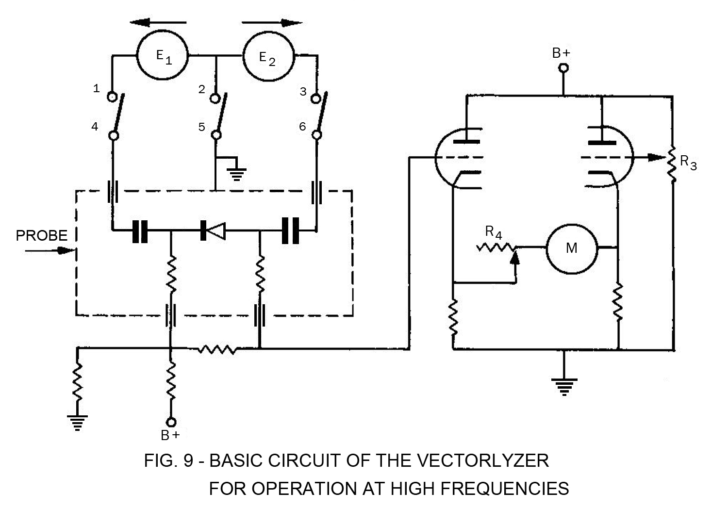
MEASURING PHASE ANGLE ABOVE 100 KC THROUGH PROBE:
Fig. 9 shows the basic circuit of the instrument when it is operated at very high frequencies. Coaxial probe is supplied with the instrument. Fig. 10 shows a circuit diagram of a coaxial probe, connectors A and B for signal sources E1 and E2 of which their terminating resistors or loads are connected respectively at connectors C and D. Duotriode T7 is arranged as a balanced cathode follower, Symbol M represents the output meter. Potentiometer R3 is used for zero adjustment. E1 and E2 are the two unknown voltages. Meter M reads E1 – E2 when both E1 and E2 are applied to the probe.
 §§§§§§§§§
Per consultare le altre schede scrivere “Vectorlyzer” su Cerca.
Foto di Claudio Profumieri, elaborazioni e ricerche di Fabio Panfili.
Per ingrandire le immagini cliccare su di esse col tasto destro del mouse e scegliere tra le opzioni.