
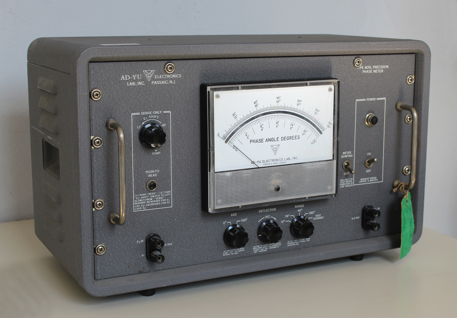
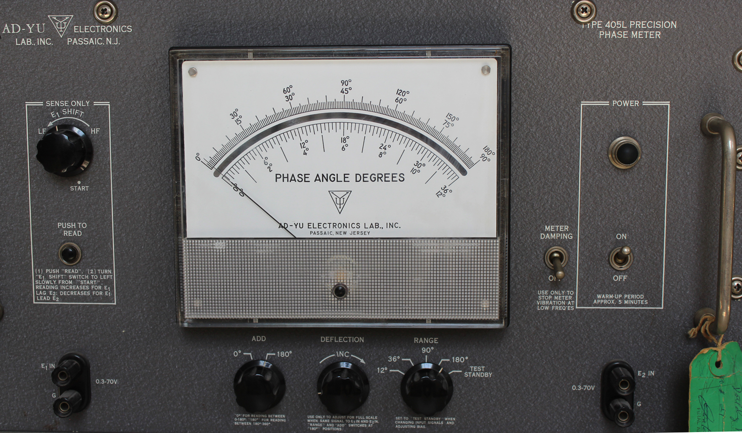
Precision Phase Meter Type 405L AD-YU Electronics Lab. Inc. Passaic. N. J. Prima parte.
Nel cartellino verde visibile in diverse foto vi è la data “2/20/63” almeno così pare di leggere, cioè 20 febbraio 1963.
Nell’inventario D del 1956, in data 28 maggio 1963, al n° 3284 si legge: “Ing. Mario Vianello – Milano. Misuratore di fase. Dest. Elettronica”.
Abbiamo così un indizio sia dell’anno di acquisto dello strumento sia che si tratti di questo strumento.
Nel collaudo eseguito dalla ditta si legge la data: 28 novembre 1962.
E in uno dei due manuali di istruzioni si legge: “Manufactured in USA June 1962”.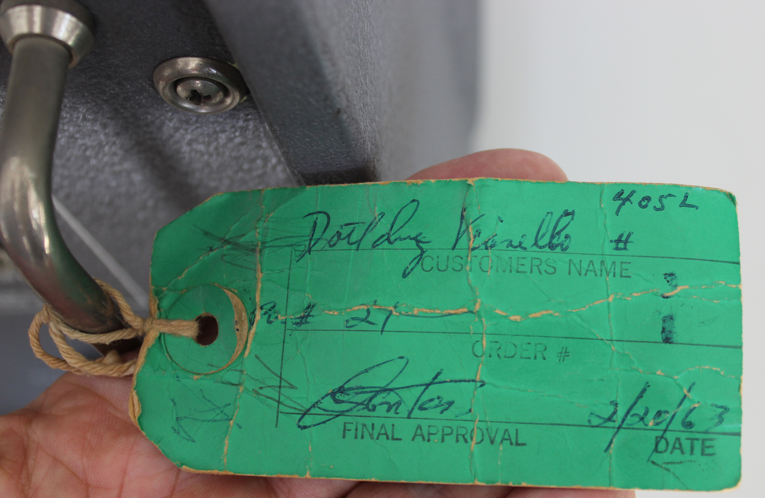
Nella Sezione Elettronica sono conservati due manuali di istruzioni con un allegato dattiloscritto che riguardano questo strumento. Ne riportiamo alcune parti.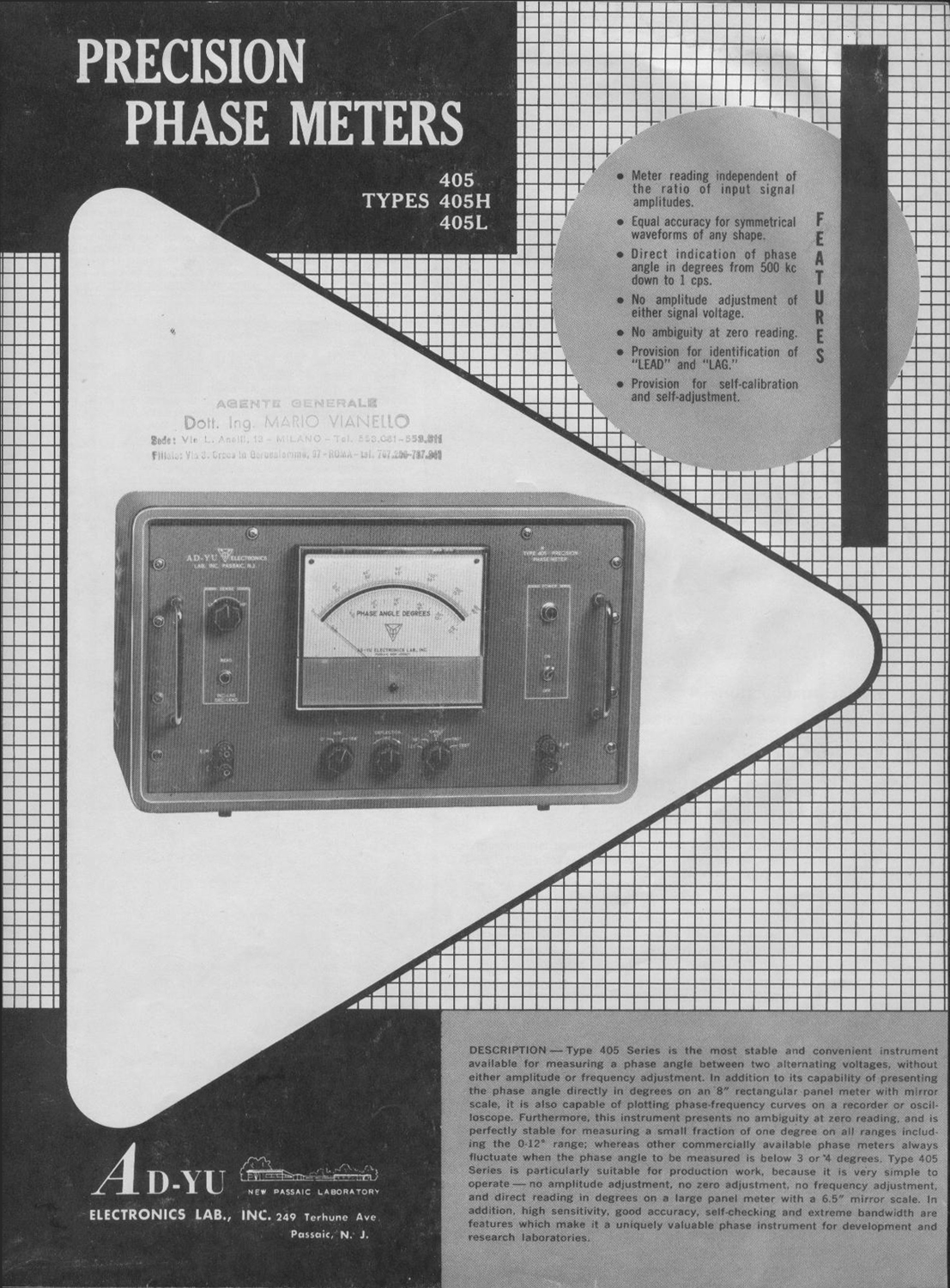
§§§
A NOVEL METHOD FOR ADJUSTMENT OF SYMMETRICAL SQUARE WAVES:
A simple method for adjusting the bias voltages based on the principle of zero average current for a perfectly symmetrical sine wave or square wave, which has better accuracy than the use of an oscilloscope, has been discovered and is employed in our Type 405 Series. The adjustment is made by using the d-c microammeter of the instrument (properly shunted and connected in series with Rb)- A symmetrical sine wave applied to the input terminal results in a meter reading of I1. With the input signal removed, bias voltage Ec1 is adjusted until the meter, which is now measuring the quiescent plate current of V2, is again reading I1. These steps are repeated until meter reading remains unchanged for variations in input signal amplitude from zero to maximum. Panel switches are installed in the instrument for the convenience of the operator to adjust the bias voltage of any one of the eight limiter stages by using the panel meter as indicator for symmetry. This arrangement provides a simple and convenient method to insure proper operation of the limiter stages, and increases the accuracy of the instrument.
COINCIDENT SLICER:
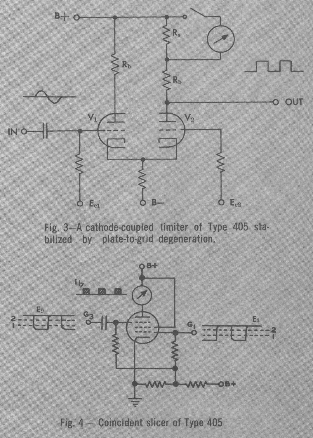
FIG. 4 shows a circuit diagram of a coincident slicer where a gated beam tube with two control grids, G1 and G3 is employed. Both G1 and G3 are biased positively with respect to their cathode and both applied signals are negative. The plate current of the gated-beam tube cannot flow unless G1 and G3 are above their cutoff value simultaneously. When either or both input signals are at their cutoff values, plate current cannot flow. In FIG. 4, E1 and E2 represent the output signals from the two last stages of the cathode-coupled limiters, CL14 and CL24. In order to have better accuracy for measuring small phase angles, the rise time of the output square waves can be made very short by introducing positive feedback to these stages. Dotted line #1 and dotted line #2 represent the cutoff and saturation levels, respectively, of the gated-beam tube used in the coincident slicer. Let lb represent the wave-form of the plate current of the coincident slicer. Since the irregularities of both input signals, such as rounded corners and overshoots, are outside the region of dotted lines #1 and #2, the plate current will not be affected by such irregularities. Another advantage of using a coincident slicer is that the output meter reading can be made virtually independent of the variations in output amplitudes of the cathode-coupled limiters, or supply voltages of the tubes.
GENERAL INTRODUCTION:
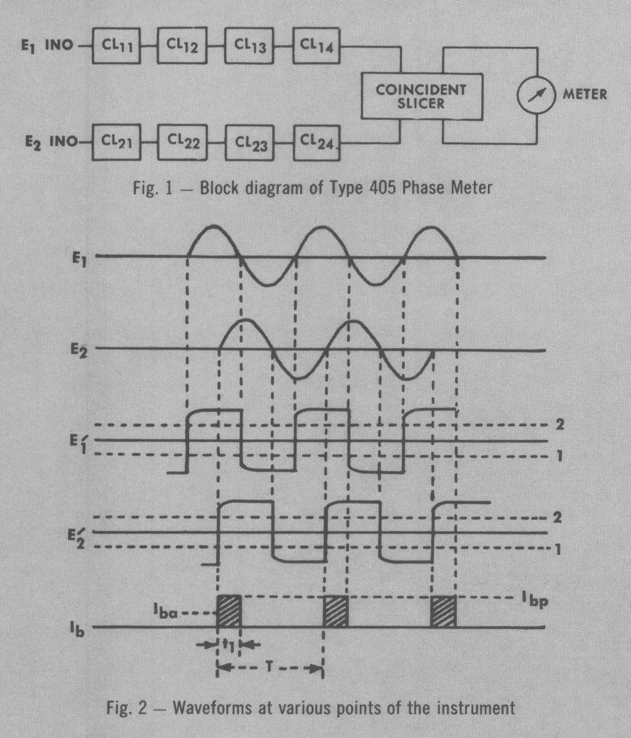
FIG. 1 shows a block diagram of Type 405 Precision Phase Meter. Input signal E1 is applied to the four-stage cathode-coupled limiter, CL11 to CL14. The function of a cathode-coupled limiter is to produce a square wave with its zero-axis intersecting points remaining identical to those of the input signal. Both input signals are first transferred into the square wave by means of two separate four-stage cathode-coupled limiters, positive feedback is provided in CL14 and CL24. for decreasing the rise time of the output square wave, and then fed into a coincident slicer circuit, which is used to activate the panel meter.
FIG. 2 shows the waveforms at various points of the instrument. E1 and E2 are input signals. E1’ and E2’ are output signals of the two cathode-coupled limiters, CL14 and CL24. Iba can be expressed as follows:
Iba = Ibp t1/T = k180° — kθ
where Ibp is the peak value of the plate current of the coincident slicer and k is a constant. It is seen, therefore, that the output meter can be calibrated to read the phase angle between E, and E: directly in degrees when either E, or E2 is shifted 180°.
CATHODE COUPLED LIMITER:
A cathode-coupled limiter is shown in Fig. 3. The grids of V1 and V2 are biased with positive potentials Ec1 and Ec2. When the input signal increases above zero, plate current of V1 increases, raising the cathode potential of both V1 and V2. Since the bias voltage of Ec2 of V2 is held constant, the grid-to-cathode potential decreases, reducing the plate current of V2 and raising its plate potential, or output. This action continues until V2 is driven to cutoff and the output can no longer follow the input but remains at the plate-supply voltage level. The output remains constant until the input to V1 reduces to a level which will permit plate current to flow again in V2. Since the grid of V2 is held constant with Ec2, tube V1 will cutoff when the input signal reduces to a certain level. At this level, the plate potential of V2 will be constant again. Before limiting action occurs, the gain of a cathode-coupled limiter is approximately equal to
μRb/2(Rb + RP),
where Rb, is the load resistance at the plate of V2, Rp is plate resistance of the tube, and μ, is the amplification factor of the tube. Using conventional duotriodes, an overall gain of 10,000 is obtained with four stages of cathode-coupled limiters. This high amplification, combined with limiting action, removes more and more of the curved portion of the input waveform until the resultant waveform at the output of the last stage is a square wave with practically vertical sides.
FEATURES
1.Meter reading independent of the ratio of input signal amplitudes.
2.Equal accuracy for symmetrical waveforms of any shape.
3.Direct indication of phase angle in degrees from 500 kc down to 1 cps.
4.No amplitude adjustment of either signal voltage.
5.No ambiguity at zero reading.
6.Provision for identification of “LEAD” and “LAG.”
7.Provision for self-calibration and self-adjustment.
DESCRIPTION-Type 405 Series is the most stable and convenient instrument available for measuring a phase angle between two alternating voltages, without either amplitude or frequency adjustment. In addition to its capability of presenting the phase angle directly in degrees on an 8″ rectangular panel meter with mirror scale is also capable of plotting phase-frequency curves on a recorder or oscilloscope. Furthermore, this instrument presents no ambiguity at zero reading, and is perfectly stable for measuring a small fraction of one degree on all ranges including the 0-12° range; whereas other commercially available phase meters always fluctuate when the phase angle to be measured is below 3 or 4 degrees. Type 405 Series is particularly suitable for production work, because it is very simple to operate — no amplitude adjustment, no zero adjustment, no frequency adjustment, and direct reading in degrees on a large panel meter with a 6.5″ mirror scale. In addition, high sensitivity, good accuracy, self-checking and extreme bandwidth are features which make it a uniquely valuable phase instrument for development and research laboratories.
APPLICATIONS
Besides the applications given in Fig. 5 to 9, there are a number of other applications, which include:
(a) Direct indication of phase characteristics with respect to frequency and/or amplitude of servo systems, process control equipment, transducers, simulators, aircraft control systems; etc. (b) Correlation between two signals can be measured with Type 405H Phase Meter and a unit of Ad-YU Type 802 or Ad-YU Type 606 Variable Delay Line. Type 802 has total delay up to 200 milliseconds, with resolution one part per, 10,000. Type 606 has 120 positions and may be driven by motor. (c) In conjunction with Ad-Yu. Type 305 Frequency Converter; Type 405 or 405H can be used to plot phase angles up to 100 mc.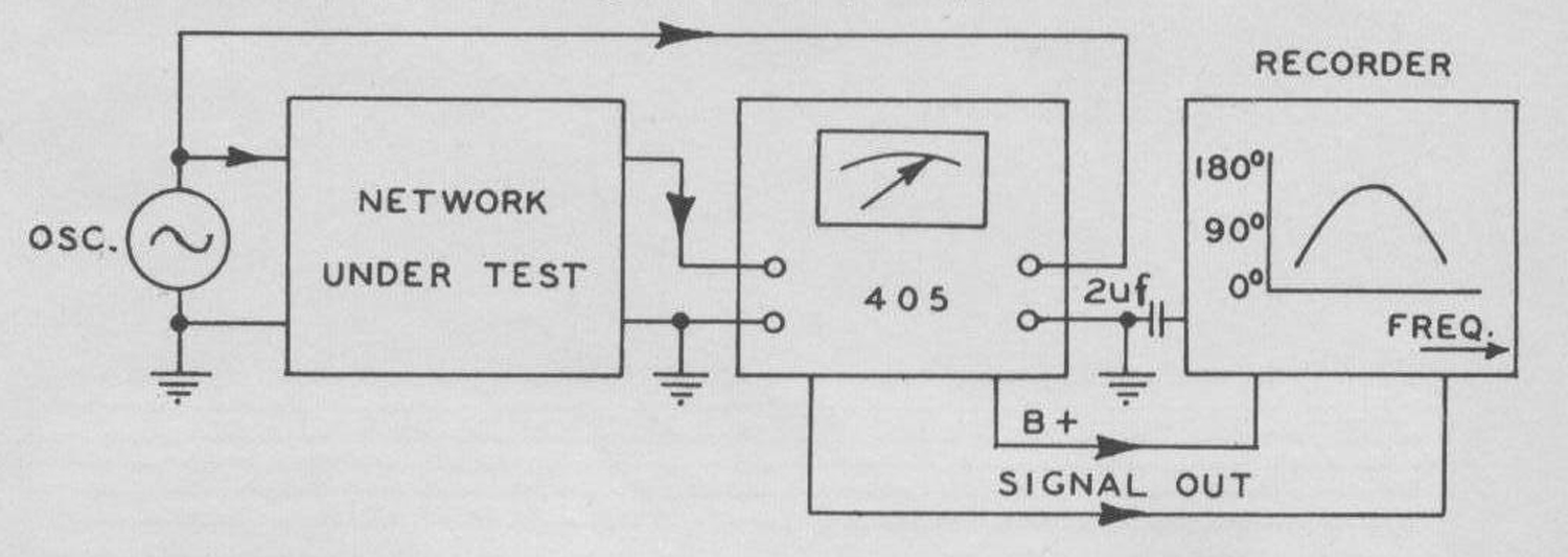 Fig. 5—Automatic plotting of phase response curve with respect to change of frequency and/or amplitude of electrical networks, can be achieved by applying the output to a recorder with both signal terminals above ground potential. A capacitor (approximately 2 μf) should be connected from the chassis of Type 405 to the ground of the recorder for filtering out hum pickup.
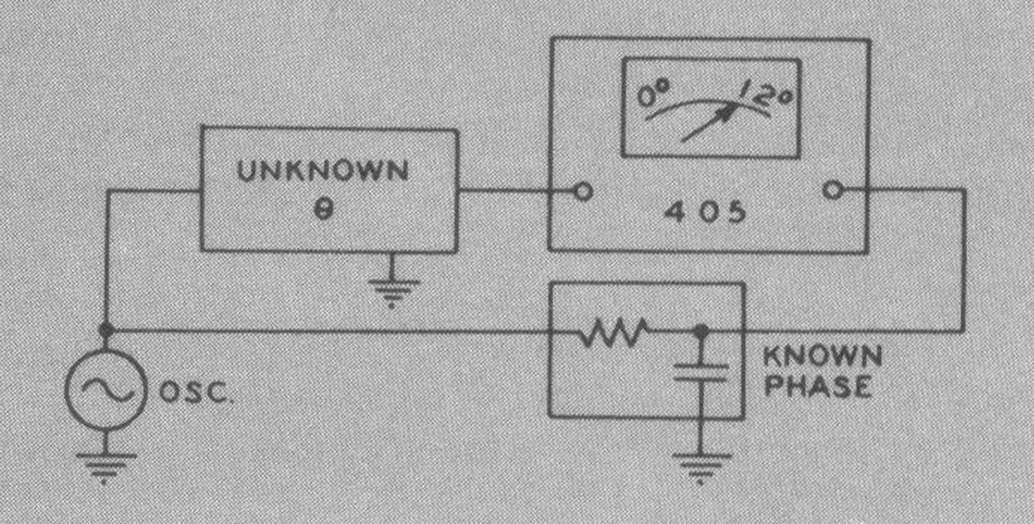 Fig. 6 – Precision phase measurement with 0.25° accuracy can be achieved in production lines by comparing a known phase shifter with the unknown network under test on the 0-12° (or 0-36°) range. The known phase shifter may be a series RC with tan θ ≃ RWC if θ is less than 90°, close coupled transformer if θ = 180°, or Ad-Yu Type 208A Precision Phase Shifter Generator.
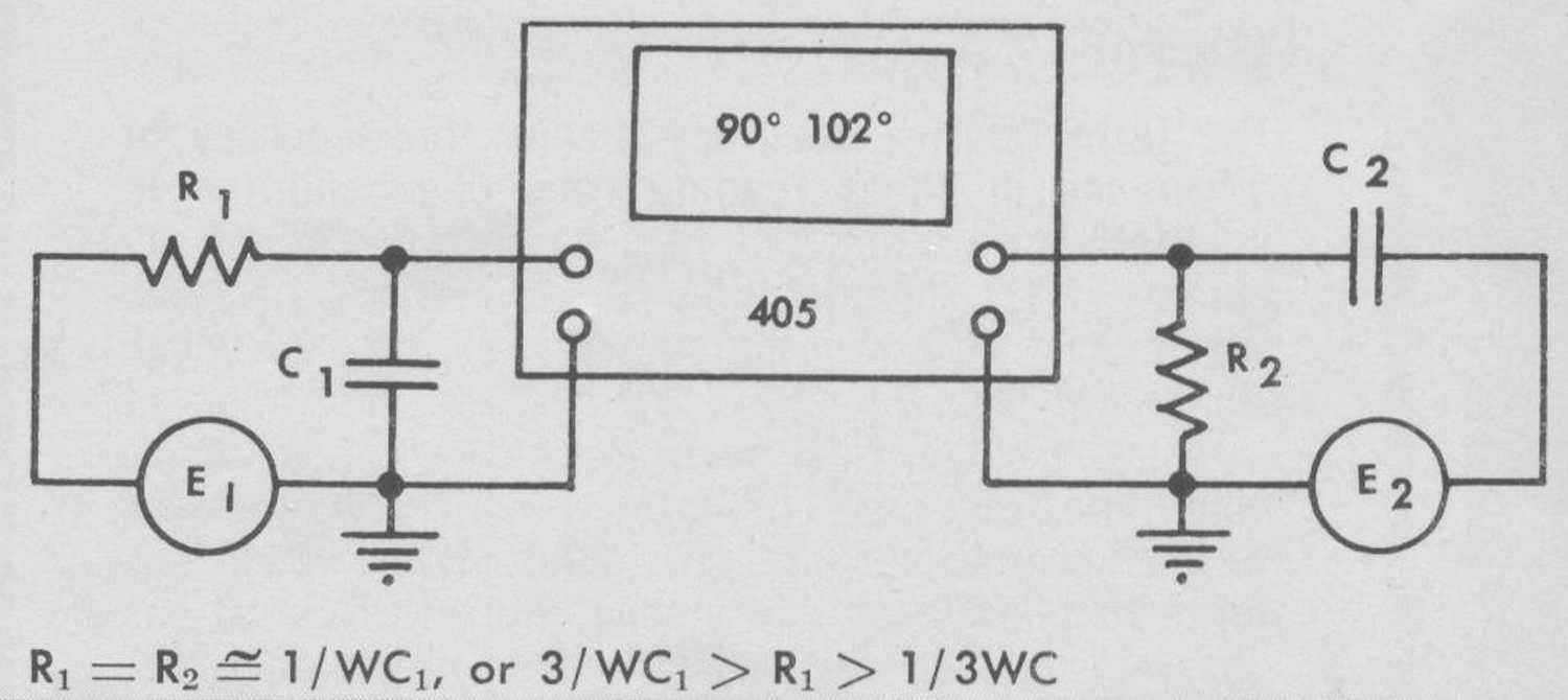
Fig. 7 – Phase measurement with error less than 0.25° in the vicinity of +90° can be accomplished by arranging R1 = R2, C1 = C2 and using the 0-12° range. For measurement in the vicinity of – 90°, interchange the positions of E1 and E2 signal sources. At 0-180° range, the meter will indicate 0° at center +90° at right -90° at left.
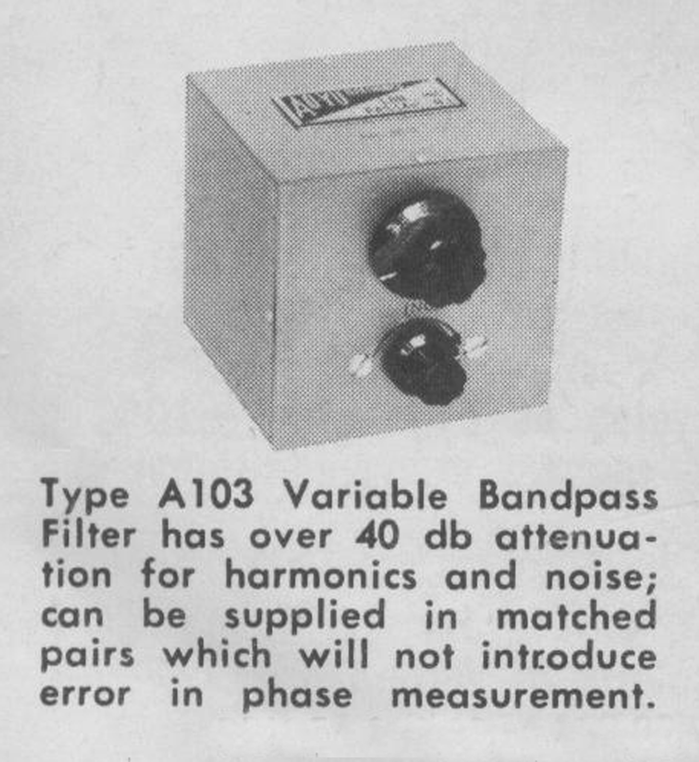
R1 = R2 ≃ 1/WC1, or 3/ WC1 > R1 > 1/ 3WC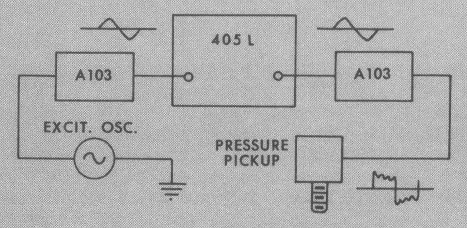 Fig. 8- Combination of Type 405L and a matched pair of A103 Band-pass Filters enables accurate phase measurement with excessively distorted signals from strain gauge, pressure pickup, transducer, vibration pickup, force transducer, etc.
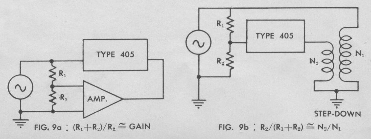 Fig. 9- A voltage divider may be used to equalize the amplitudes of two input signals for 405 series, see Fig. 9a for amplifiers, step-up transformers, etc., Fig. 9b for potentiometers, step-down transformers, etc. To minimize phase error due to stray capacitance, at least one element of the divider should be made less than 100 ohms.
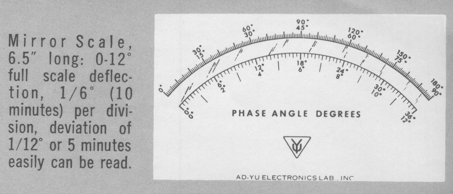
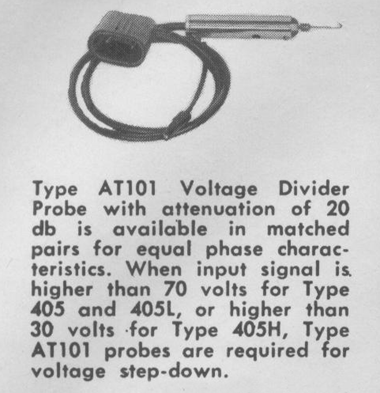
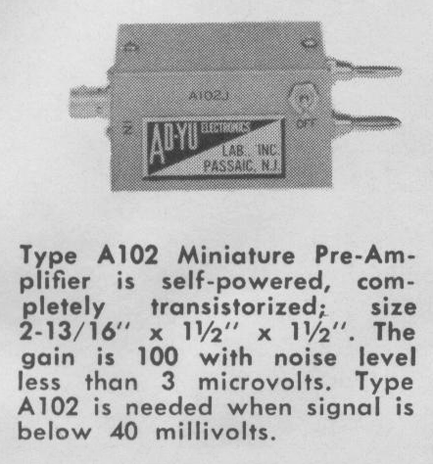
 ACCESSORIES
 SPECIFICATIONS
RESPONSE:
TYPE 405 — 8 cps to 40 kc; the upper limit can be extended to 100 kc with increasing signal amplitudes and decreasing accuracy.
TYPE 405H — 8 cps to 300 kc; the upper limit can be increased to 500 kc with increasing signal amplitudes and decreasing accuracy.
TYPE 405L — 1 cps to 40 kc; the lower limit can be extended to less than 1 cps with increasing signal amplitudes. The upper limit can be extended to 100 kc with increasing amplitude and decreasing
accuracy.
PHASE RANGE:
There are four ranges — 0-12, 0-36, 0-90, and 0-180 degrees full scale. A panel switch is provided for inserting 180 degrees phase shift in order that the above four ranges may be converted to four additional ranges; 180-192, 180-216, 180-270, 180-360. The 12° range is converted to 120° in TYPE 405H.
ACCURACY:
The term relative accuracy means the accuracy of difference in phase reading from one condition to another. For example, it may be interpreted as accuracy of (1) repeatability, (2) comparison of readings among unknown signals with respect to a given signal, (3) relative phase angle due to variation of signal characteristics, such as change of frequency, amplitude, or the characteristic of the network through which one (or both) input signal flows. The term absolute accuracy means the accuracy of the phase reading in comparison with a phase standard. All the figures quoted below for accuracy are the maximum values of errors which have been found so far for a number of instruments of this series. However, experience has shown that errors are actually much less than the figures given below for many instruments.
TYPE 405 – The relative accuracy is ±0.25°, and the absolute accuracy is ±1° or 2% at any range up to 40 kc; the error increases slowly up to ±3% at 100 kc.
TYPE 405H – The relative accuracy is ±0.25°, and the absolute accuracy ±1° or 2% at any range up to 300 kc; the error increases slowly up to ±3% at 500 kc.
TYPE 405L – The relative accuracy is ±0.25° and the absolute accuracy is ±1° or 2% at any range from 1 cps up to 40 kc; the error increases slowly above 40 kc to 3% at 100 kc; below 1 cps, the error is due to slow movement of the meter pointer at signal frequency. For all three types the absolute accuracy is much less than 1° when measuring small phase angles.
INPUT VOLTAGE:
The phase reading on the panel meter is not affected by the fluctuation of signal amplitudes in either one or both input channels within the ranges listed below.
“Manufactured in USA June 1962”.
TYPE 405 — The signal voltage can be varied from 0.3 volt to 70 volts rms from 8 cps to 40 kc (0.1 volt possible with relaxed accuracy); the lower limit increases slowly to 0.5 volt at 100 kc. The d.c. component should not be more than 400 volts. TYPE 405H — The signal voltage can be varied from 2 volts to 40 volts rms from 8 cps to 250 kc (with relaxed accuracy, 0.3 volt possible below 100 kc, 1 volt possible below 300 kc). The d.c. component should not be more than 400 volts.
TYPE 405L — The signal voltage can be varied from 0.3 volt to 70 volts from 1 cps to 40 kc (0.1 volt possible with relaxed accuracy); the lower limit increases for frequencies below 1 cps and above 40 kc. The d.c. component should not be more than 200 volts.
INPUT SIGNAL RATIO:
Meter reading is completely independent of the ratio of signal amplitudes, ranging from ratios of 1 to 100 for TYPE 405 and 405L, and 1 to 20 for TYPE 405H.
INPUT IMPEDANCE:
TYPE 405 and 405H – 3 megohms shunted by 20 μμf on both input channels.
TYPE 405L — 6.8 megohms shunted by 20 μμf.
INPUT POWER:
60 watts, 50/60 cycles at 110 volts ±10% (220 volts ±10% available on request at no additional charge).
STABILITY FOR MEASURING SMALL PHASE ANGLES:
Drift is less than 0.01° for 10 hours of continuous operation at the vicinity of zero degree.
CHARACTERISTIC OF OUTPUT SIGNALS:
The output signal for external recorder taken at the meter terminal is a pulse of constant amplitude with repetition rate equal to the input signal frequency and duty cycle proportional to the phase angle between two input signals. Both the repetition rate and duty cycle follow instantly any change of input signal frequency and phase angle. An integrating circuit with time constant of 0.1 second is connected in series between the meter terminal and the “OUT” jack at the rear of the chassis. The output impedances are 3.6 k and 360 k respectively before the integrating circuit and after. Output voltage referring to B+ is zero for 0° increases linearly to -14 volts for 180° in 405 and 405L to -4 volts for 405H, decreases again to zero from 180 to 360°.
WAVEFORM DISTORTION:
Reading is not affected by harmonics which are 0° and 180° with the fundamental components. Harmonics, which result in difference of time duration between the positive and negative portion of the waveform, will produce error.
This error can be minimized by using a matched pair of AD-YU Type A103 filters.
PHYSICAL SIZE AND PRICE:
Panel— 19″ × 10%”, rack mount. Chassis—17″ × 8%” × 2¼”. Cabinet—12″ × 10″ × 20%”, light gray wrinkle finish. Type 405—$668, Type 405H—$725, Type 405L—$735.
OPERATING PROCEDURE
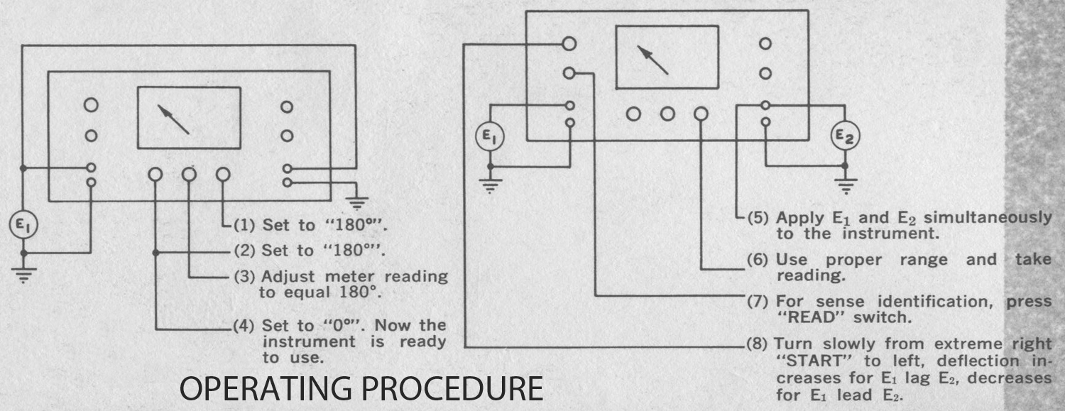 1.Plug line cord into 110 volts (220 volts available on request). 50/60 cycles. Set “RANGE” switch to 180° and “ADD” switch to 180°.
2.Apply to both “E1 IN” and “E2 IN” a signal greater than 0.3 and smaller than 70 volts for 405 and 405L. 2 to 40 volts for 405H.
3.Adjust “DEFLECTlON INC.” potentiometer for 180° reading on the meter. Now turn “SHIFT” switch to 0° and the instrument is ready for use.
4.Apply two signals separately to “E1 IN” and “E2 IN” and take readings.
5.To identify the SENSE of the meter reading, turn SENSE E1 SHIFT control to the extreme right, push “READ” switch, then turn E1SHlFT control slowly to left until the meter reading starts to increase if E1 lags E2, or starts to decrease if E1 leads E2. lf meter reading does not change, or changes illogically, it is probably due to the amplitude of E1 being too high.
CAUTION:
Set “RANGE” to “TEST” to prevent damage of meter pointer by changing leads.
BIAS ADJUSTMENT: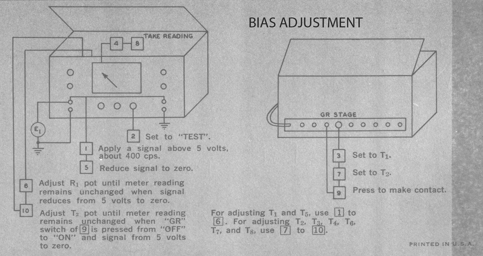 Bias controls R1 to R8 on top of chassis should be adjusted if meter reading varies with change of signal is applied to both inputs, or replacement of tubes in the limiter stages.
1.Apply a single signal about 400 cps, 5 volts or more, symmetrical with respect to the zero axis to both “E1 IN” and “E2 IN”.
2.Set “RANGE” switch to “TEST”.
3.Set “STAGE” switch at rear to “T1” .
4.Take meter rading.
5.Reduce input signal to zero. This may done by grounding “IN” binding post for T1 and T5 stages, or pressing “GR” push button switch at rear and removing in put signal for other stages.
6.Adjust “R1” until meter reading equals that of Step No. 4.
7.Repeat above steps several times to insure that the output plate current of T1 remains unchanged when signal varies from zero to over 10 volts. Then turn “STAGE” switch to “T2” and adjust bias pot constant. Use similar procedure for R3. Order of adjustment must be made from first, second, third, then the output stage, such as R1 to R3 and R5 to R7, because the input signal of the stage being adjusted must be symmetrical with respect to the zero axis. Adjustment of R4 and R8 are normally un necessary. If adjustment are needed, the procedure for 405H is identical to that of R2. The procedure for 405 and 405L is as follows: Connect an oscilloscope to the plate of T4 and adjust R4 until the output square wave at the plate of T4 becomes symmetrical with input signal above 5 volts and above 100 kc at “E1 IN”. The procedure for adjusting R8 is similar to R4.»
§§§
Per consultare la seconda parte scrivere “405L” su Cerca.
Foto di Claudio Profumieri, elaborazioni e ricerche di Fabio Panfili. Testo a cura di Fabio Panfili.
Per ingrandire le immagini cliccare su di esse col tasto destro del mouse e scegliere tra le opzioni.