 Vectorlyzer Type 202 AD-YU Electronics Lab. Inc. Passaic, N. J. . Seconda parte.
Nell’inventario D del 1956, in data 28 maggio 1963, al n° 3285 si legge: “Ing. Mario Vianello – Milano. Vectorlyzer. Dest. Elettronica. ₤ 710.000” .
Il prof. Luigi Silenzi ricorda di averlo usato, ma alcuni di noi allievi dell’epoca non ne hanno memoria, forse perché è uno strumento per applicazioni veramente complesse che esulavano dai programmi di insegnamento.
Abbiamo trovato negli archivi della Sezione Elettronica il manuale delle istruzioni originali risalente al marzo del 1961.
Invece di trascrivere una traduzione affrettata, ed anche per mantenere l’efficacia dell’originale, ne riportiamo alcune parti in inglese.
§§§§§§§§§
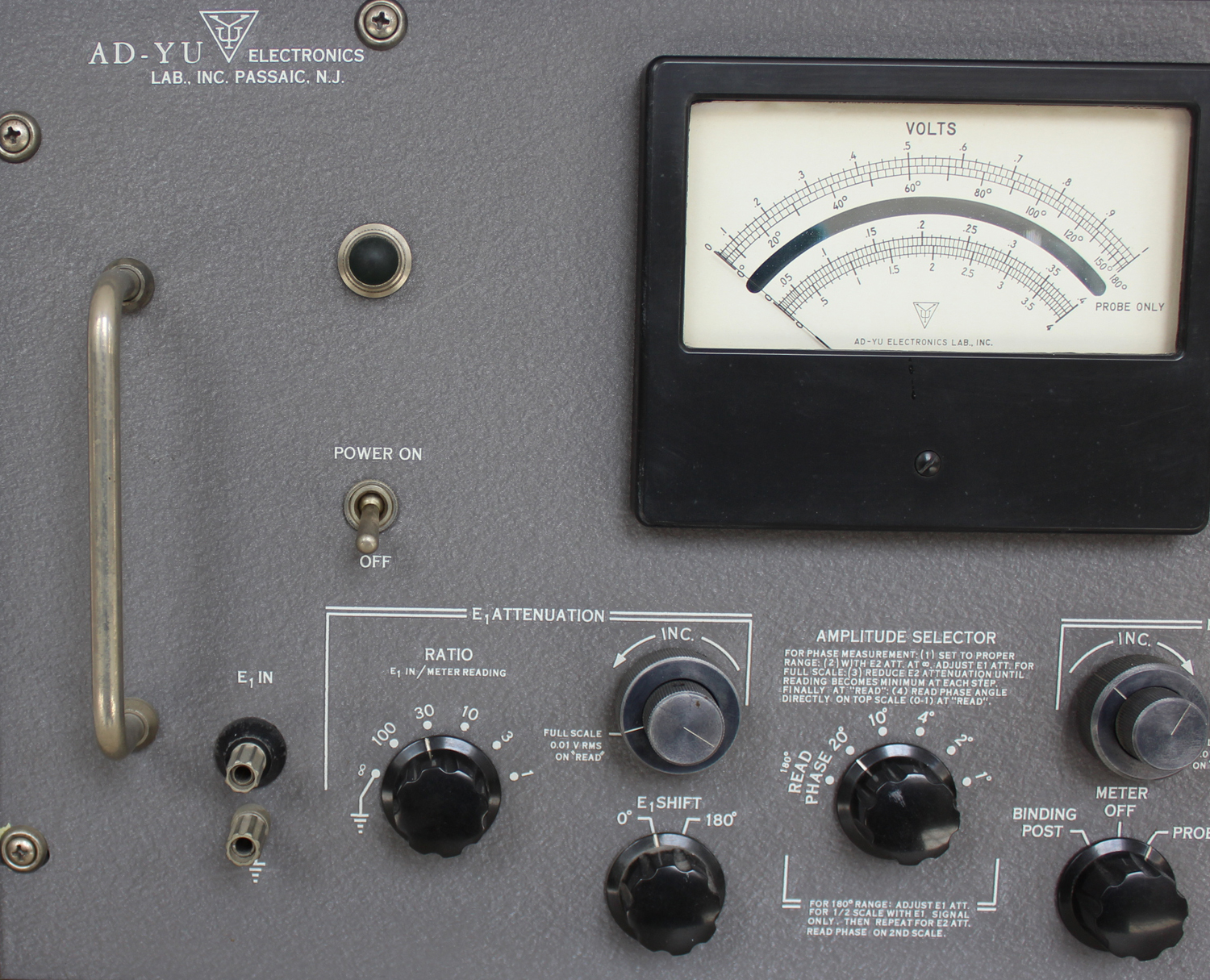
TYPE 202 VECTORLYZER
CIRCUIT DESCRIPTION:
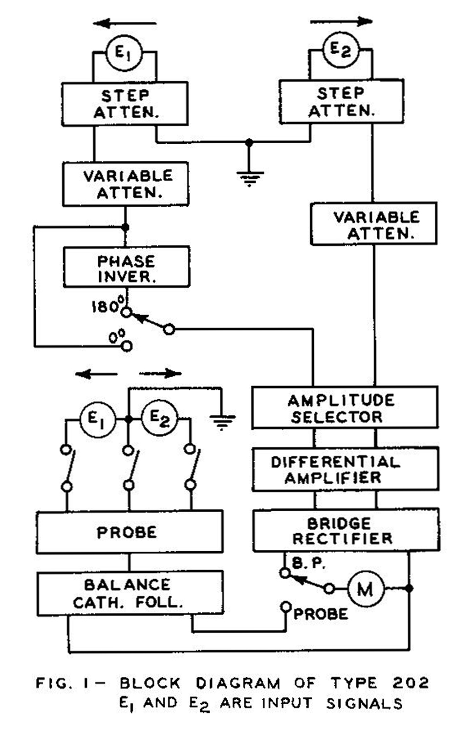
Type 202 Vectorlyzer is essentially a combination of the following elements: Two step attenuators, two continuously adjustable attenuators, a wide-band phase inverter, a degenerative vector difference amplifier, a bridge rectifier, a balanced cathode follower, a high frequency probe, and a regulated power supply, These elements, except the regulated power supply, are arranged as shown in the block diagram of Fig. 1.
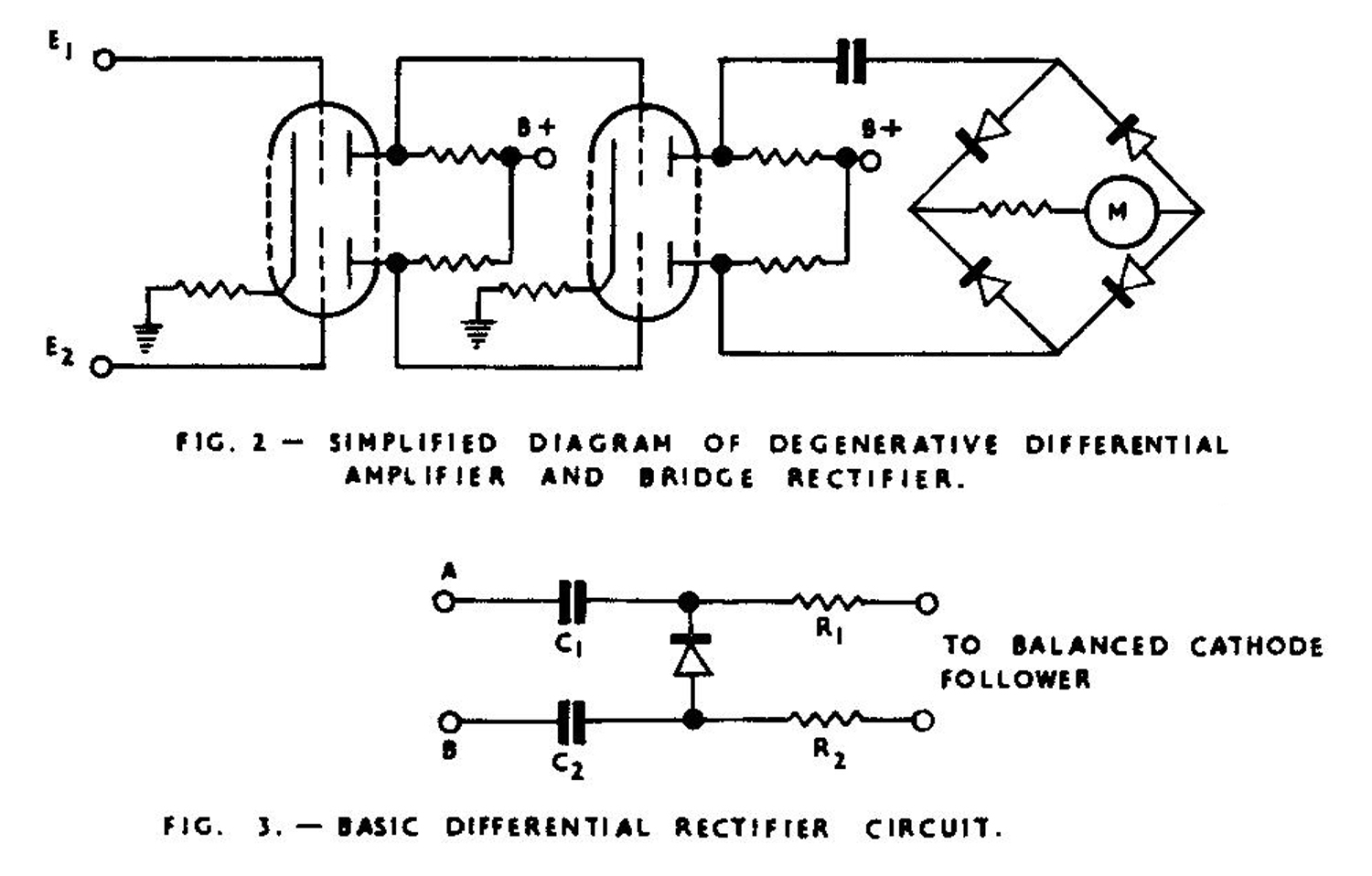
The differential amplifier has two stages, see Fig. 2.
The “AMPLITUDE SELECTOR” control consists of two cathode followers and one 2-pole, 6-position switch. The switch is connected at the cathode circuits of the cathode followers for changing the amount of voltages applied to the differential amplifier. The high frequency probe consists of a differential rectifier, which is a special type of peak rectifier capable of producing a direct current potential at its output terminals proportional to the vector difference between the two voltages applied to its input terminals, see Fig. 3.
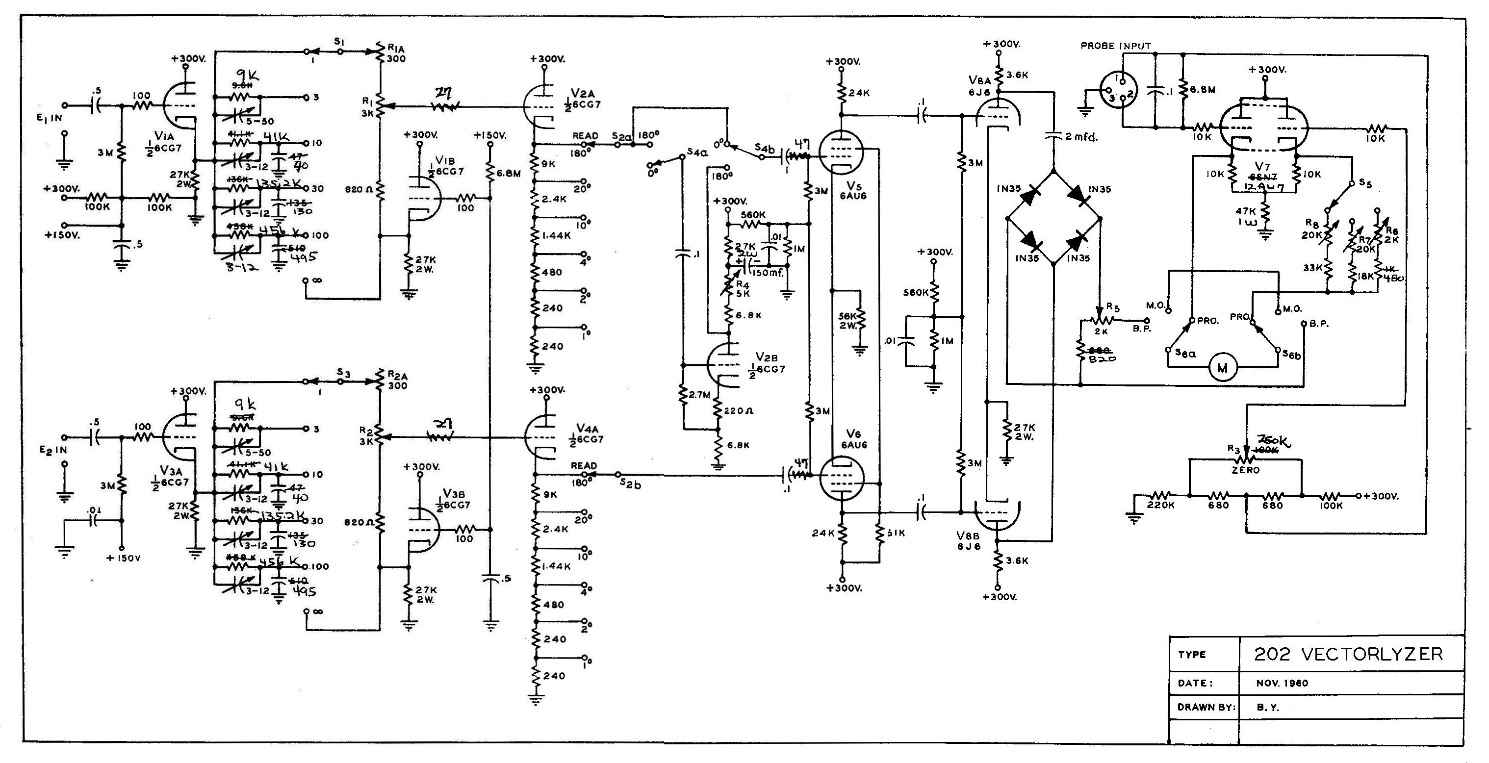
 COMPLETE CIRCUIT DIAGRAM:
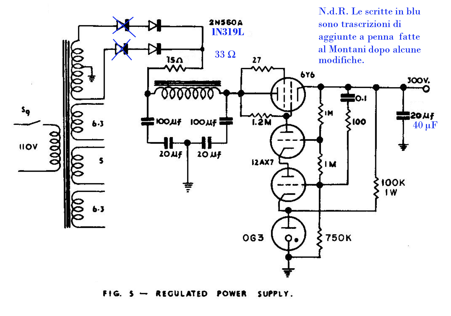
A complete schematic diagram of Type 202 Vectorlyzer, except its regulated power supply, is shown in Fig. 4. The second half of V2 is used as a phase inverter, V1 and V3 are connected as cathode followers for both variable attenuators. The first halves of V2 and V4 are used in the “AMPLITUDE SELECTOR” control for measuring small phase angle. D1 to D4 are employed as bridge rectifier. Twin-triode V7 is arranged as a balanced cathode follower and is used to excite the panel output meter, Fig. 5 shows the regulated power supply for this instrument.
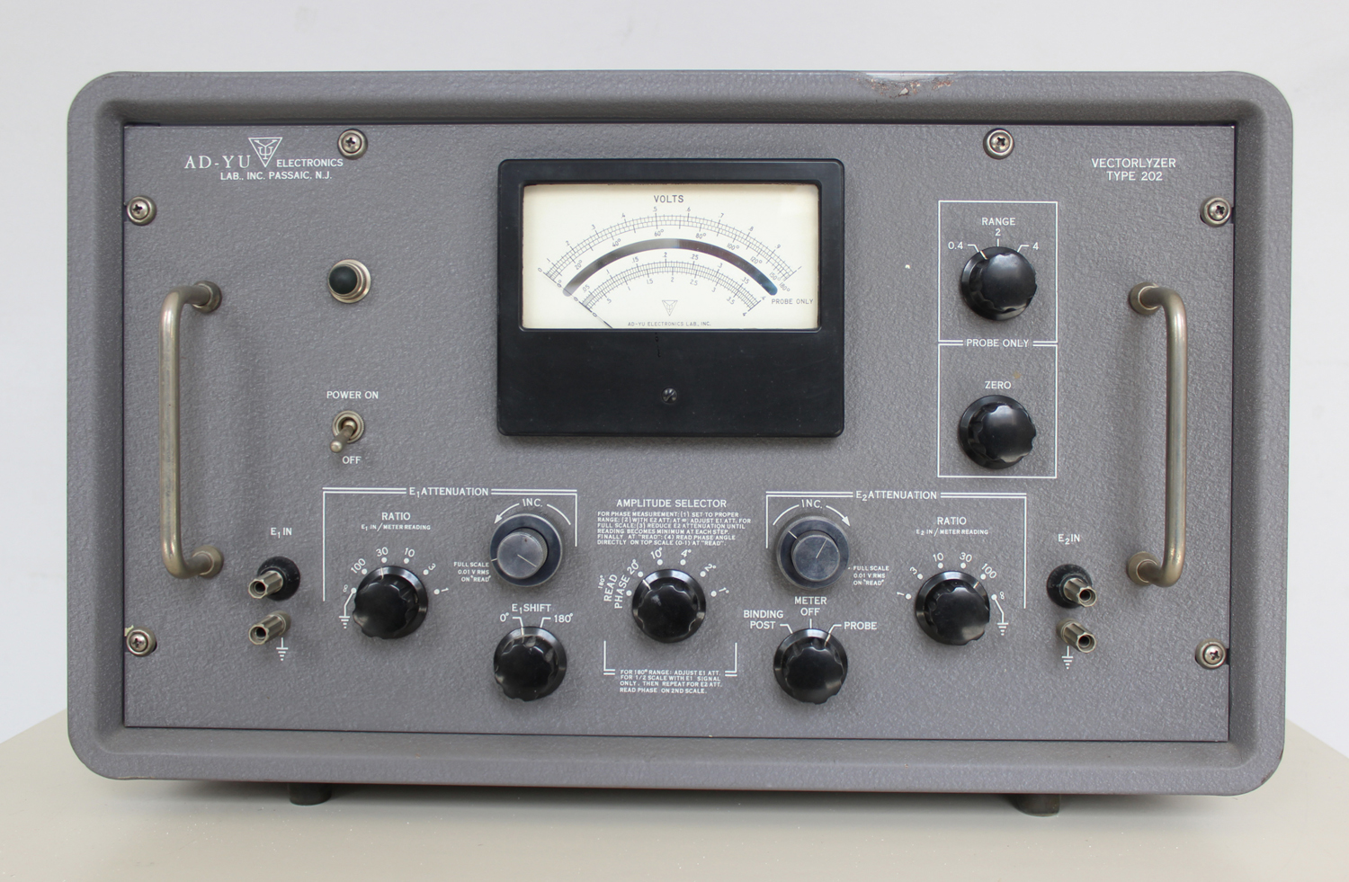
DESCRIPTION OF FRONT PANEL CONTROLS AND TERMINALS:
1.“POWER ON”, toggle switch, S9 in Fig. 5 – Used to turn on or to turn off the power.
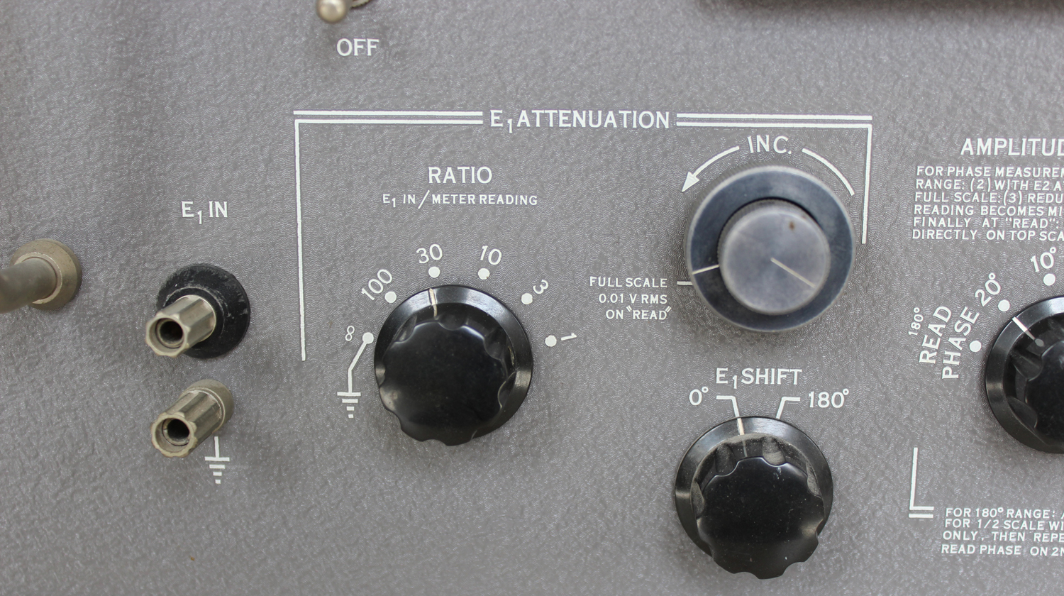
2.“E1 IN” binding post, provides for connection of an input signal to E1 channel.
3.“E1 ATTENUATION RATIO, E1 IN/Meter Reading”, 2-pole, 6-position switch, S1 in Fig. 4, select the attenuation ratio for input signal at “E1 IN” binding post to meter reading.
4.“E1 ATTENUATION INC.”, 3k – 300 ohm coaxial potentiometers, R1 and R1a in Fig. 4. – This acts as a continuous adjustment of the signal amplitude in E1 channel with 3k pot as coarse control and 300 ohm pot as fine control.
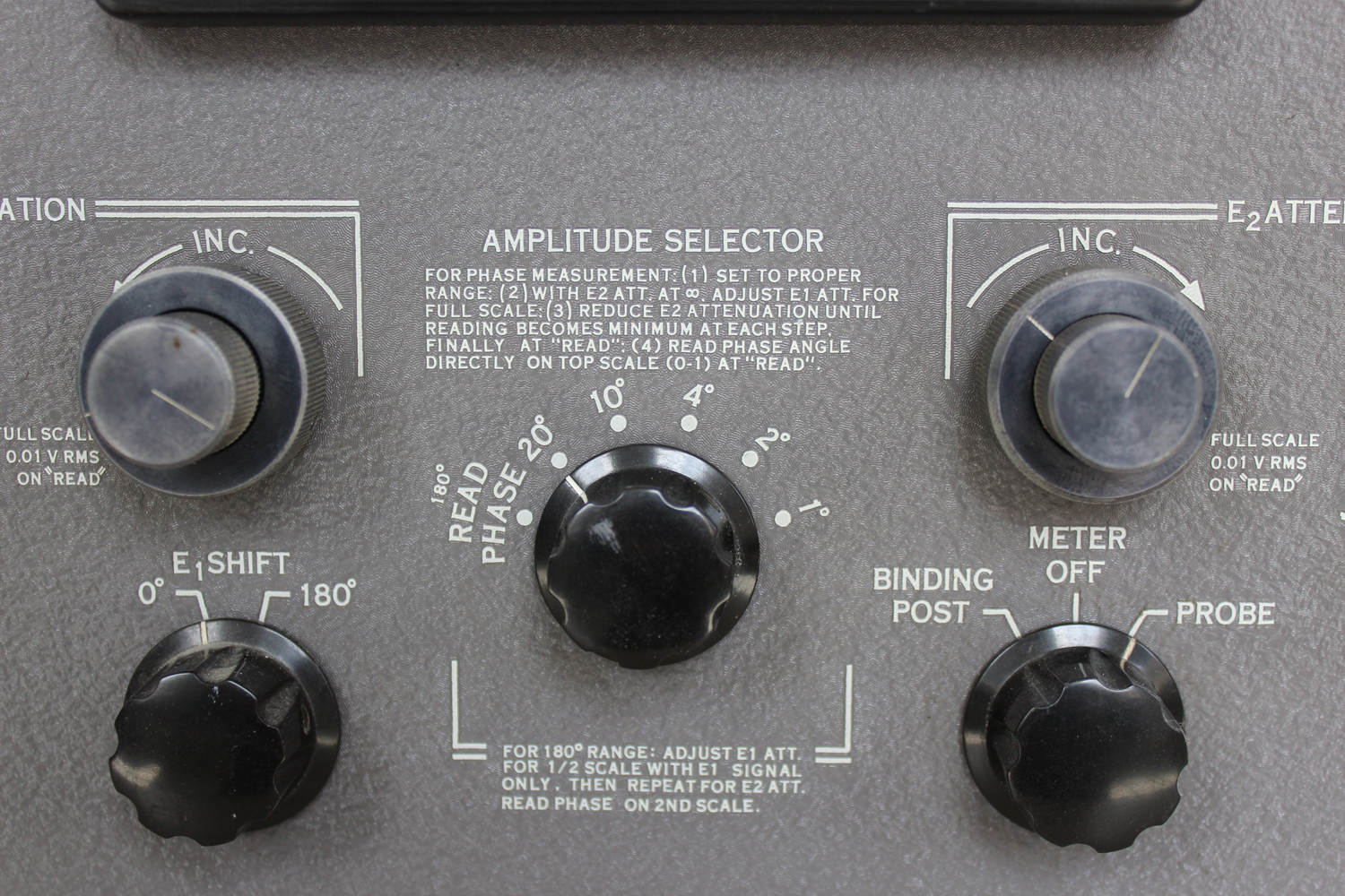
5.“E1 SHIFT”, 0-180°, 2-pole, 2-position switch, S4 in Fig. 4. – Introduce a phase shift of 180° at the 180° position by inserting a phase inverter stage to V2, introducing no phase shift at 0° position in which V2 is by-passed.
6.“AMPLITUDE SELECTOR”, 2-pole, 6-position switch, S4 in Fig. 4. – This control is used for measuring small phase angles. First set to the desired full scale phase sensitivity position, adjust amplitudes of E1 (or E2) to full scale, then adjust E2 (or E1) for minimum meter deflection, Phase angle can now be read directly on the first scale at “READ” position. This control should always be set at “READ” position for all other measurements, otherwise the sensitivity of the instrument is low.
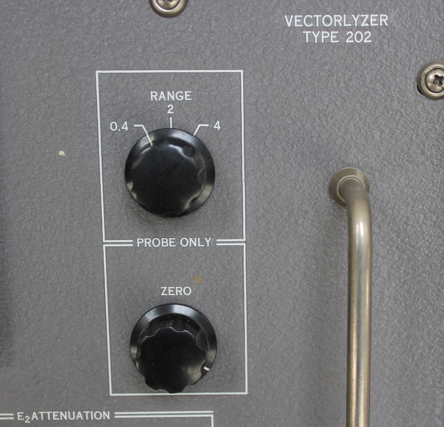
7.“METER ZERO”, 100k potentiometer, R3 in Fig. 4. – This control is used to zero the output meter only when the probe is being used. No electrical zeroing is needed for binding post input.
8.“E2 ATTENUATION INC.”, 3k – 300 ohm coaxial potentiometers, R2 and R2a in Fig. 4. This serves as continuous adjustment of the signal amplitude in E2 channel with 3k pot as coarse adjustment, 300 ohm pot as fine adjustment.
9.“BINDING POST, METER OFF, PROBE”, 2-pole, 3-position switch, S6 in Fig. 4. – Serves (1) to connect the panel meter to the output of the bridge rectifier D1 – D4 when the input signals are applied to binding post, (2) to short the meter terminal in order not to damage the panel meter when the input signals are being connected or disconnected (3) to connect the panel meter to the output of the balanced cathode follower when input signals are applied to probe.
10.“E2 ATTENUATION RATIO, E2 IN/Meter Reading”, 2-pole, 6-position switch S3 in Fig. 4. Select the attenuation ratio for input signal at “E2 IN” binding post to meter reading.
11.“E2 IN”, binding post, – provides for connection of an input signal to E2 channel.
12.“PROBE RANGE”, 1-pole, 3-position switch, S5 in Fig. 4. – Select sensitivity of the panel meter when the probe is used for 0.4, 2 and 4 volts rms full scale.
13.“ATTENUATOR PROBE” – Two attenuator probes having 40 db attenuation and input capacitance of 4 μμF are supplied with the unit in order to extend all voltage ranges by 100 times.
WARNING:
1.Ground: In order to avoid undesirable pickup, the instrument must always be grounded together with all input sources. One ground point for one device or one signal source is recommended for avoiding pickup loop.
2.“BINDING POST, METER OFF, PROBE”, should be set at “METER OFF” when not in use to prevent excessive damage of panel meters.
§§§§§§§§§
Nota: La data riportata nello schema ( Fig. 4) è NOV. 1960.
Per consultare le altre schede scrivere “Vectorlyzer” su Cerca.
Foto di Claudio Profumieri, elaborazioni e ricerche di Fabio Panfili.
Per ingrandire le immagini cliccare su di esse col tasto destro del mouse e scegliere tra le opzioni.