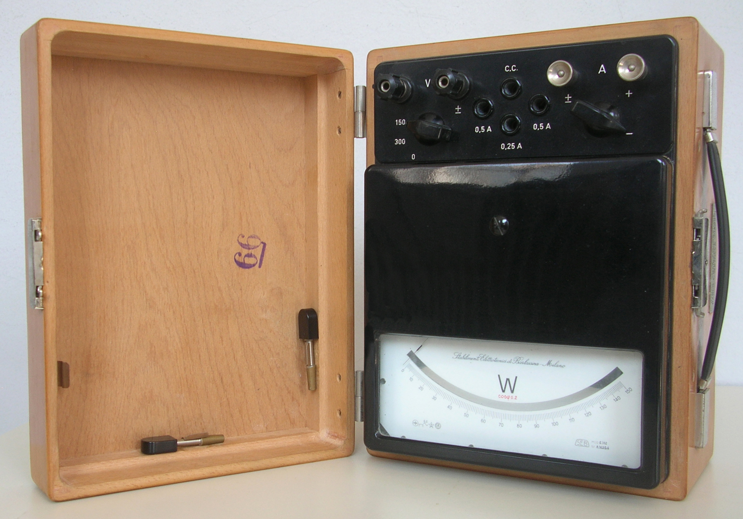
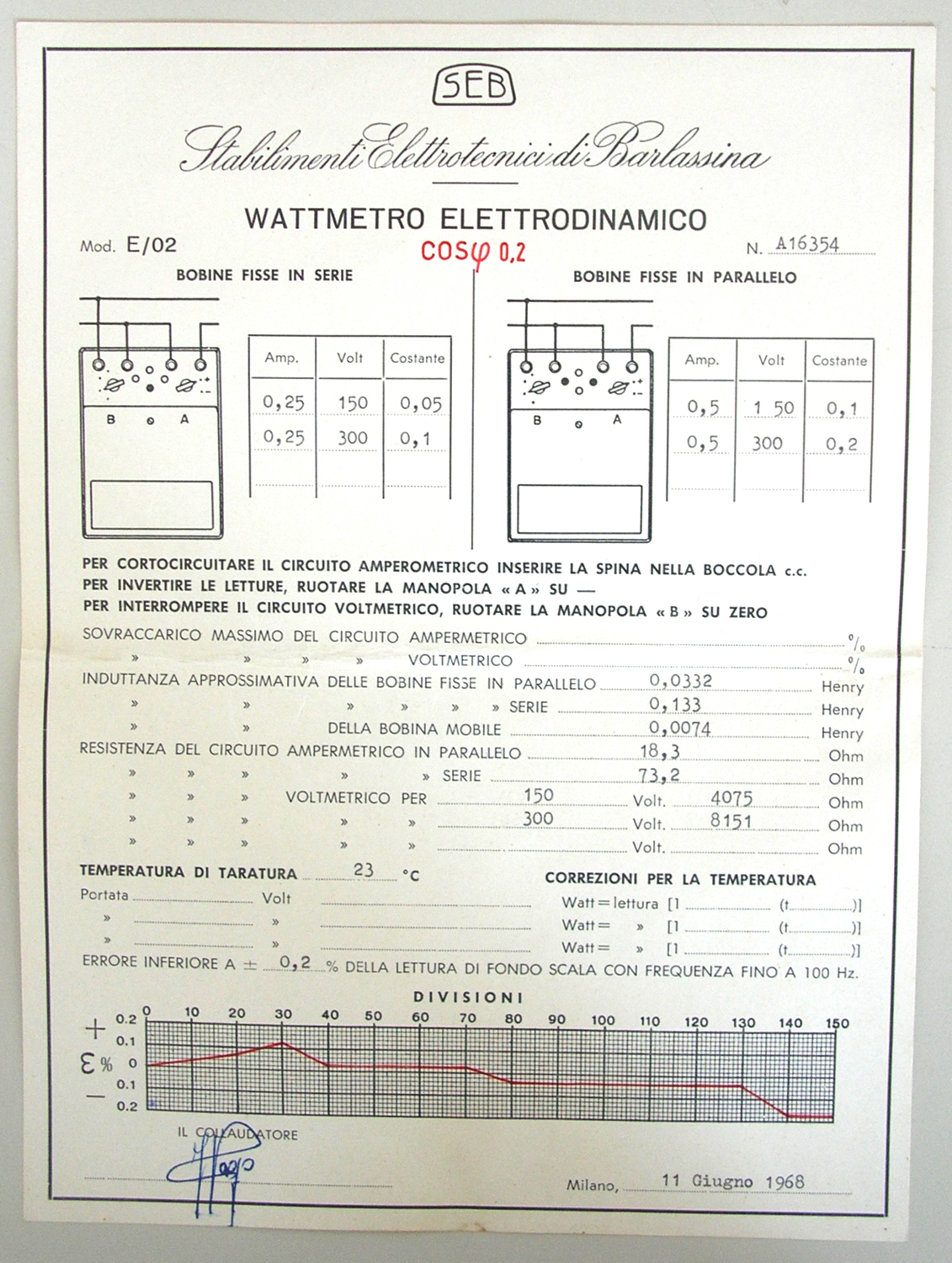
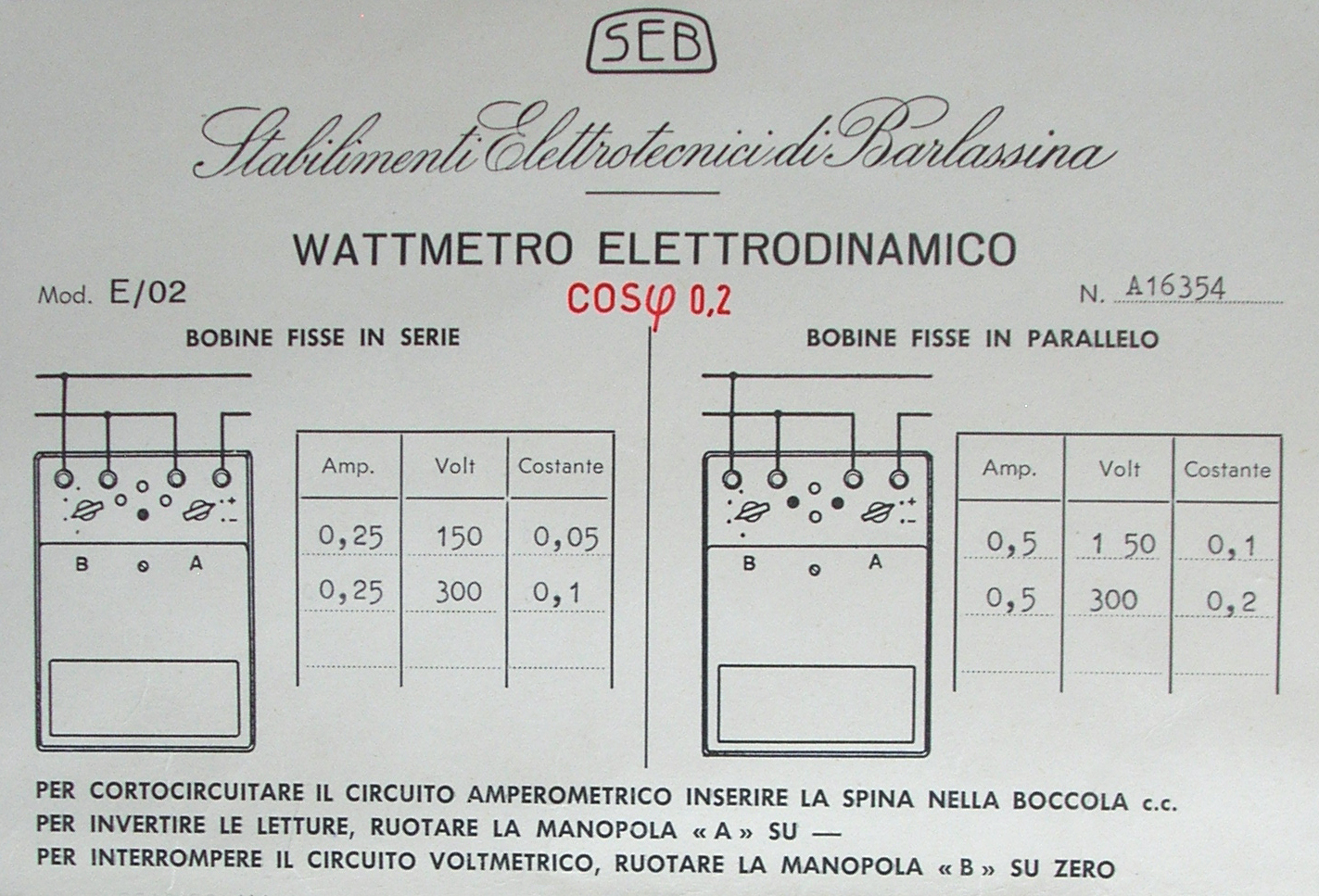
Wattmetro elettrodinamico SEB Mod. E/02, matr. N° A16354.
Collaudato dalla ditta SEB (Stabilimenti Elettrotecnici di Barlassina – Milano) l’11 giugno 1968.
Nell’Estratto dell’inventario del laboratorio di Elettronica si trova al n° 223, dove si legge: “Giugno 1968. Wattometro E/02 per C.C. E C.A. N° A/16354” e si rimanda all’inventario generale n° 4386. Destinato alla sezione Elettronica. In realtà esso misura solo in C.A. .
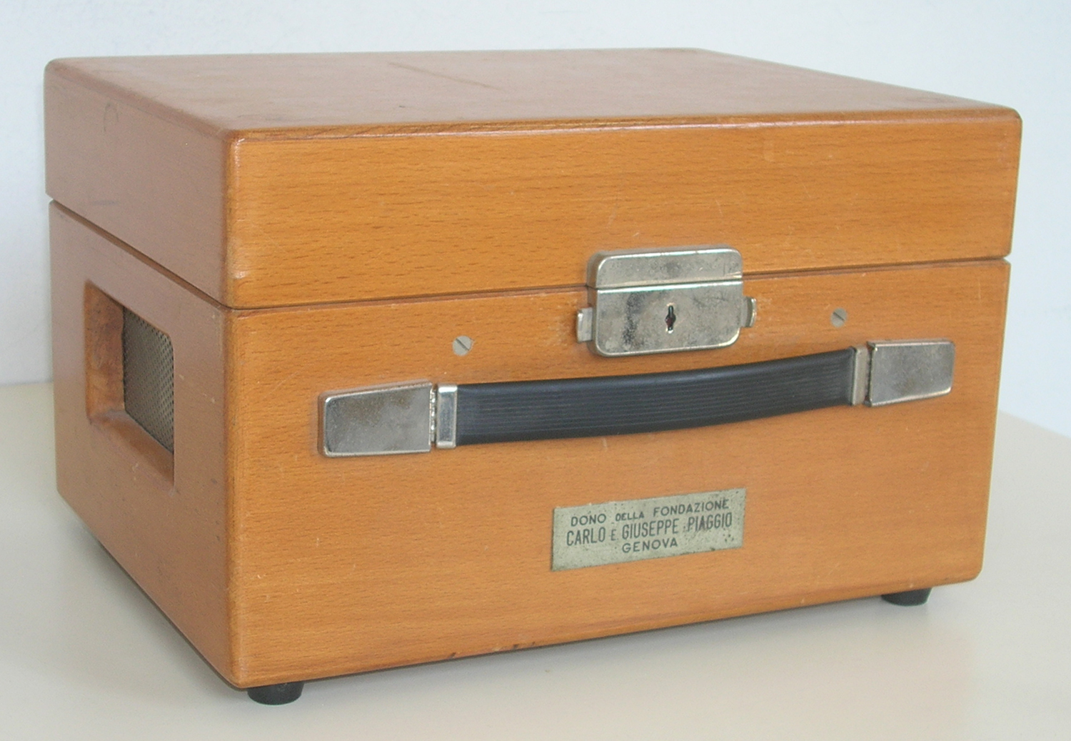
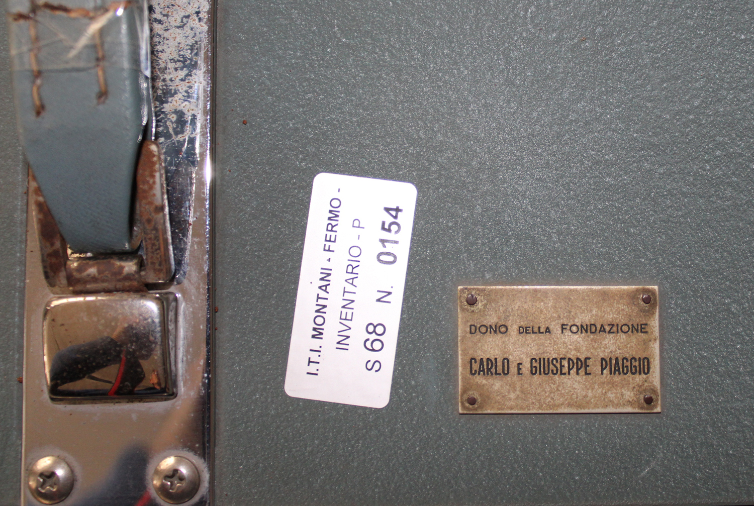
Un’etichetta, posta sul contenitore reca la scritta: «DONO DELLA FONDAZIONE CARLO E GIUSEPPE PIAGGIO – GENOVA».
Le sue dimensioni sono: (28 × 21 × h18) cm.
Sul quadrante i simboli delle norme CEI dicono che lo strumento è del tipo elettrodinamico con ferro; classe 0,2; misura in C. A.; tensione di prova 2 kV; da usarsi in posizione orizzontale.
In alto al centro in carattere corsivo si legge: “Stabilimenti Elettrotecnici di Barlassina – Milano“; al centro vi è una grande “W” e appena sotto in rosso “cos φ 0,2”.
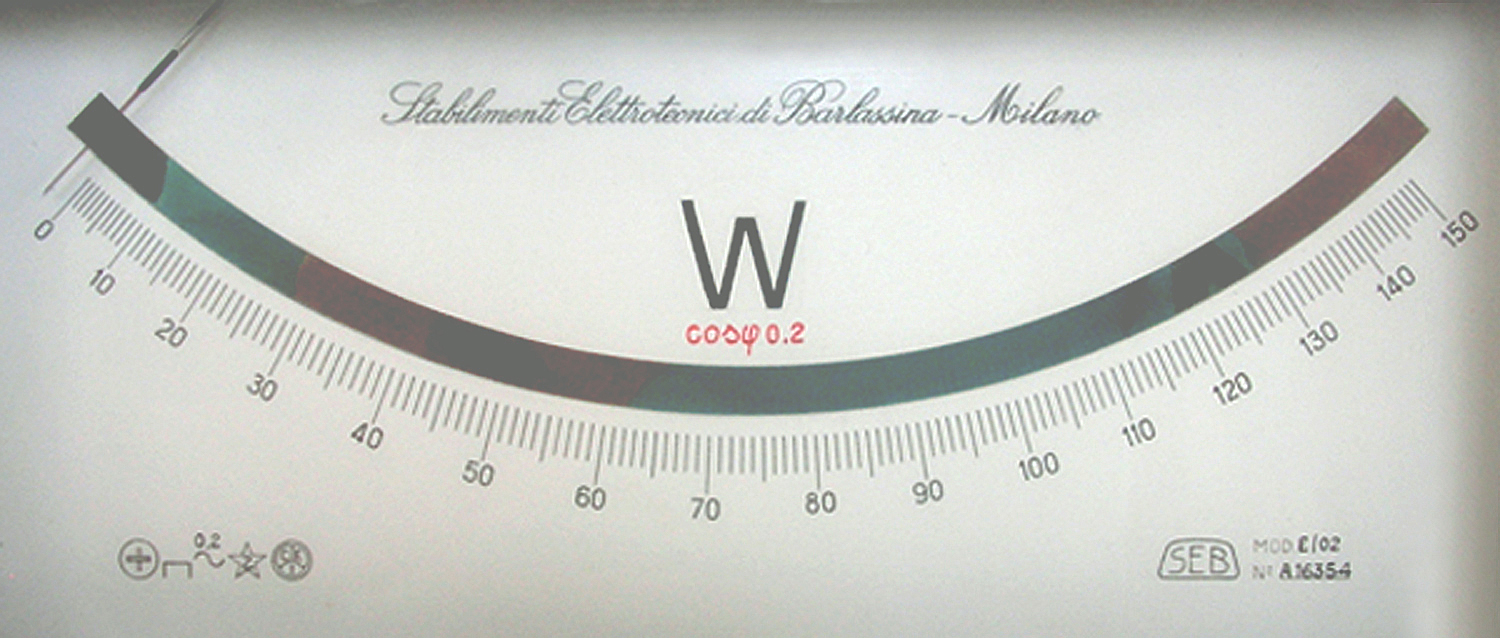
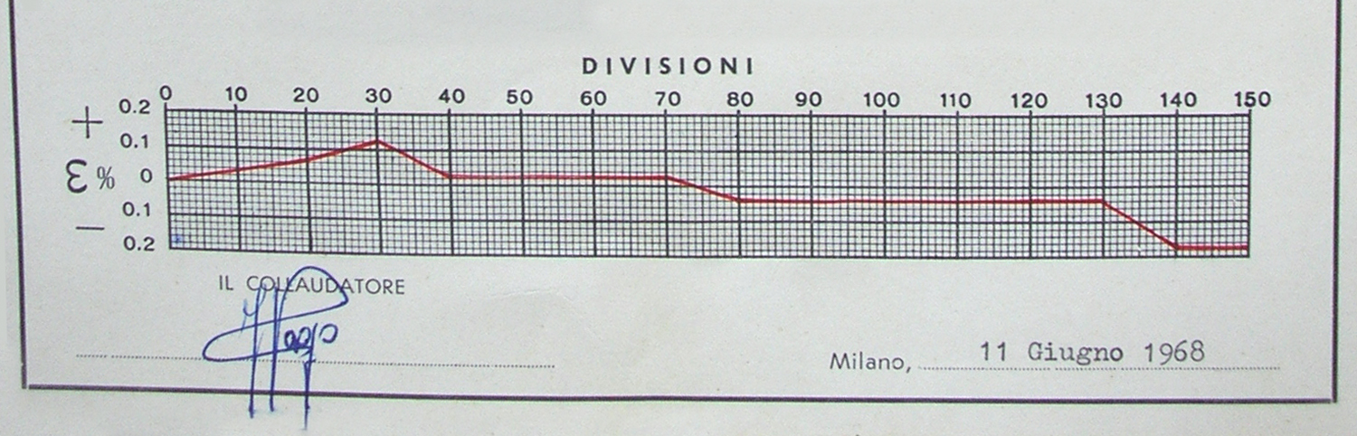
La scala, che presenta 150 divisioni, fino al centro ha un andamento simile a quello quadratico, ma poi le linee vanno infittendosi di nuovo verso il fondo scala: è evidente la sua costruzione empirica, con l’ausilio di strumenti campione.
A sinistra in basso vi è il logo della ditta con la scritta:
“MOD. E/02 N° A16354”.
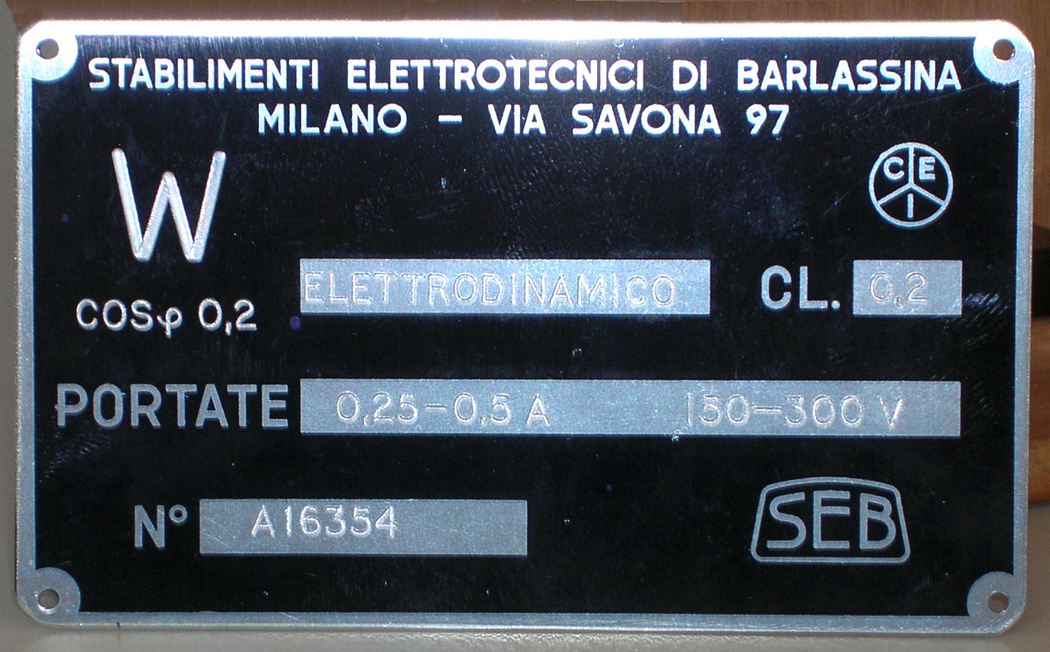
Un’etichetta di alluminio posta sul retro reca la scritta: «STABILIMENTI ELETTROTECNICI DI BARLASSINA MILANO – VIA SAVONA 97. W ELETTRODINAMICO. CL. 0,2. PORTATE 0,2 – 0,5 A 150 – 300 V. N° A16354. SEB».
Il foglio di collaudo, posto all’interno del coperchio, reca lo schema di inserzione e le tre portate con le relative costanti per la lettura sulle due scale.
Ne riportiamo una parte per comodità del visitatore:
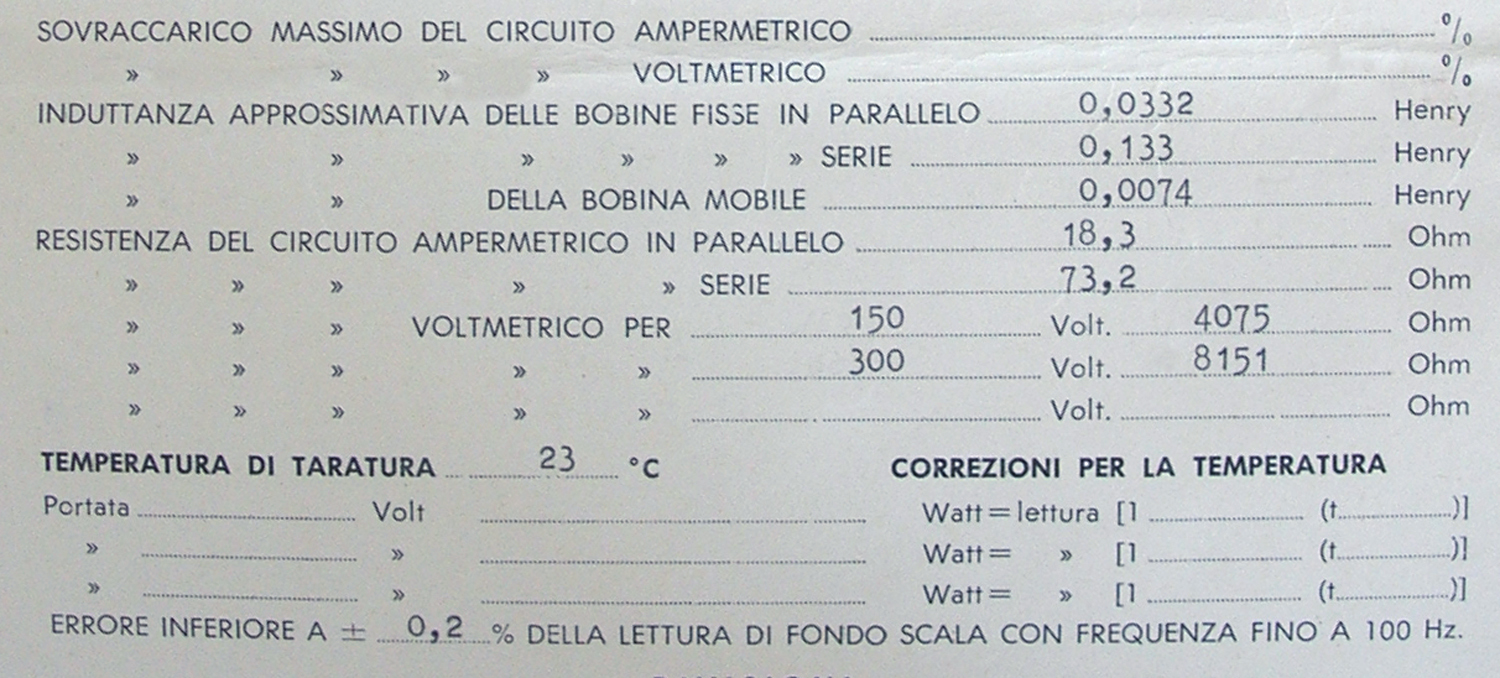
«PER CORTOCIRCUITARE IL CIRCUITO AMPEROMETRICO INSERIRE LA SPINA NELLA BOCCOLA c.c. . PER INVERTIRE LE LETTURE, RUOTARE LA MANOPOLA “A” SU − . PER INTERROMPERE IL CIRCUITO VOLTMETRICO, RUOTARE LA MANOPOLA “B” SU ZERO. …. (omissis) . INDUTTANZA APPROSSIMATIVA DELLE BOBINE FISSE IN PARALLELO: 0,0332 Henry; INDUTTANZA APPROSSIMATIVA DELLE BOBINE FISSE IN SERIE: 0,133 Henry. INDUTTANZA APPROSSIMATIVA DELLA BOBINA MOBILE: 0,0074 Henry. RESISTENZA DEL CIRCUITO AMPERMETRICO IN PARALLELO: 18,3 Ohm. RESISTENZA DEL CIRCUITO AMPERMETRICO IN SERIE 73,2 Ohm . RESISTENZA DEL CIRCUITO VOLTMETRICO PER 150 Volt: 4075 Ohm. RESISTENZA DEL CIRCUITO VOLTMETRICO PER 300 Volt: 8151 Ohm . TEMPERATURA DI TARATURA 23°C. ERRORE INFERIORE A ± 0,2 % DELLA LETTURA DI FONDO SCALA CON FREQUENZA FINO A 100 Hz. [Sotto vi sono: il diagramma dell’errore percentuale in funzione delle divisioni fino a 150 di fondo scala e la firma del collaudatore N.d.R.]. Milano, 11 Giugno 1968».
Le cause di errore nella misura sono di tre tipi: autoconsumo, errore di fase, classe.
Uno strumento elettrodinamico è costituito essenzialmente da una bobina fissa e da una bobina mobile; quando le due bobine sono percorse da correnti sinusoidali, sulla bobina mobile agisce una coppia, il cui valor medio è proporzionale al prodotto tra i valori efficaci delle due correnti e il coseno dell’angolo di sfasamento tra le correnti stesse.
Uno strumento di questo tipo fornisce l’indicazione della potenza attiva assorbita da un carico se una delle due bobine, solitamente quella fissa, è attraversata dalla corrente che entra nel carico, mentre l’altra, solitamente quella mobile, è attraversata da una corrente che in modulo è proporzionale alla tensione presente ai capi del carico.
Ciò si ottiene semplicemente ponendo un resistore di valore opportuno in serie alla bobina mobile.
Tuttavia, poiché‚ la bobina mobile presenta un’induttanza non nulla, la corrente che attraversa questa bobina risulta sfasata rispetto alla tensione applicata ai suoi capi di un certo angolo che durante la misura si va sommare allo sfasamento vero e proprio del circuito oggetto della misura stessa.
La caratteristica più importante di questo strumento è il basso coseno di φ (utile per le misure a basso fattore di potenza) che lo rende idoneo per il rilievo della potenza elettrica attiva di un carico o di un circuito elettrico a forte connotazione induttiva; nel quale caso l’errore di fase diventerebbe sensibile.
Esso fa parte degli strumenti più pregiati nei quali la molla antagonista è ridotta in modo che la portata dello strumento sia pure ridotta. Un wattmetro con cos φ = 0,2 non può essere usato per carichi che assorbano una potenza attiva pari a 1/5 di quella corrispondente al prodotto V I, essendo V la portata voltmetrica e I quella amperometrica; cioè esso è vulnerabile ai sovraccarichi.
Foto di Claudio Profumieri, elaborazioni, ricerche e testo di Fabio Panfili con la consulenza di Sergio Iuvalè che ringrazio.
Per ingrandire le immagini cliccare su di esse col tasto destro del mouse e scegliere tra le opzioni.
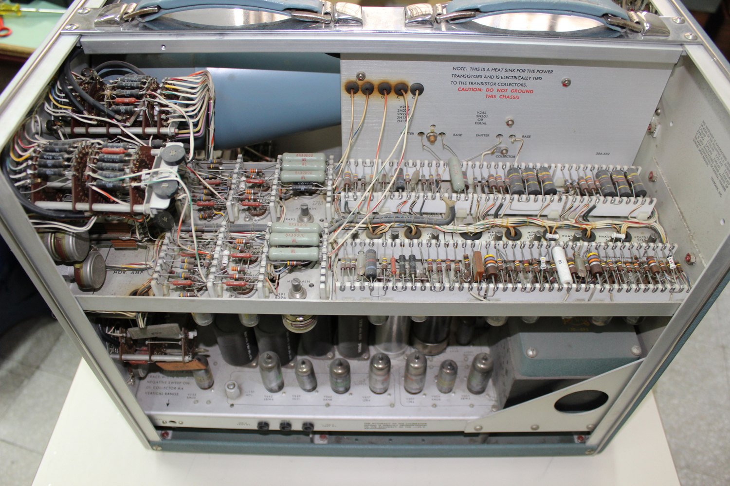
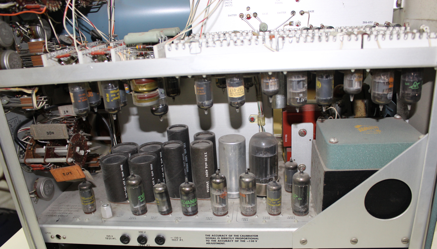
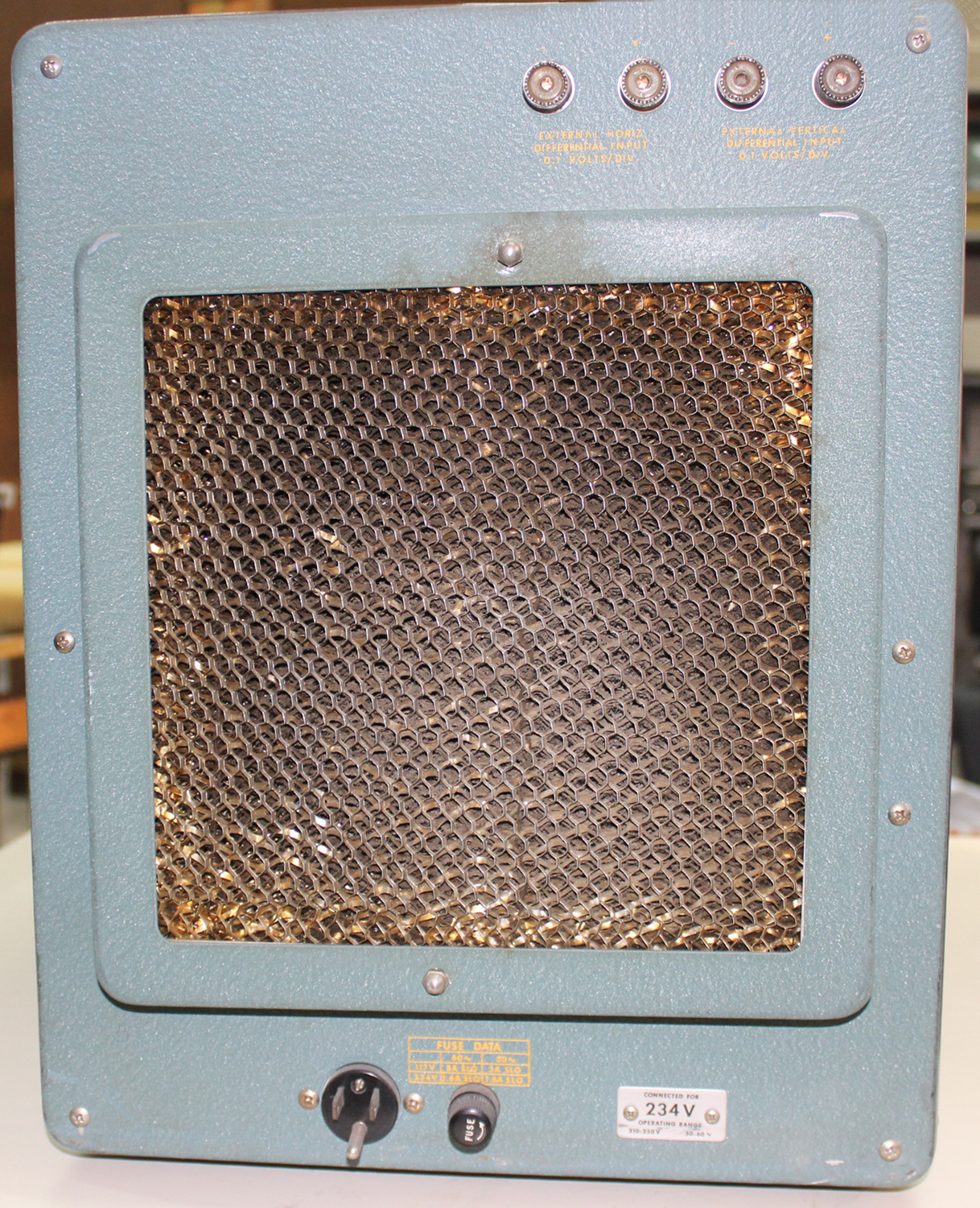
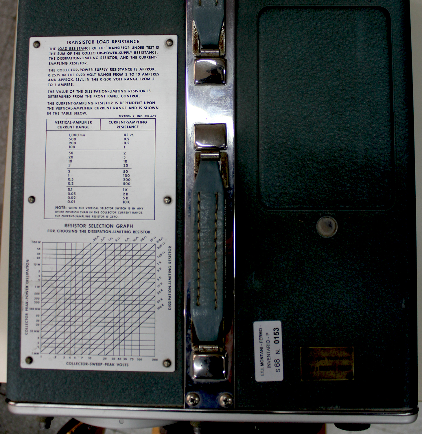
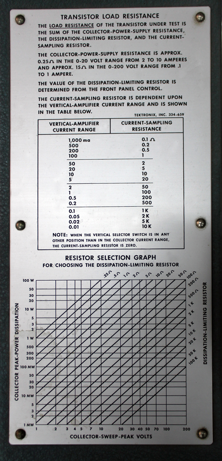
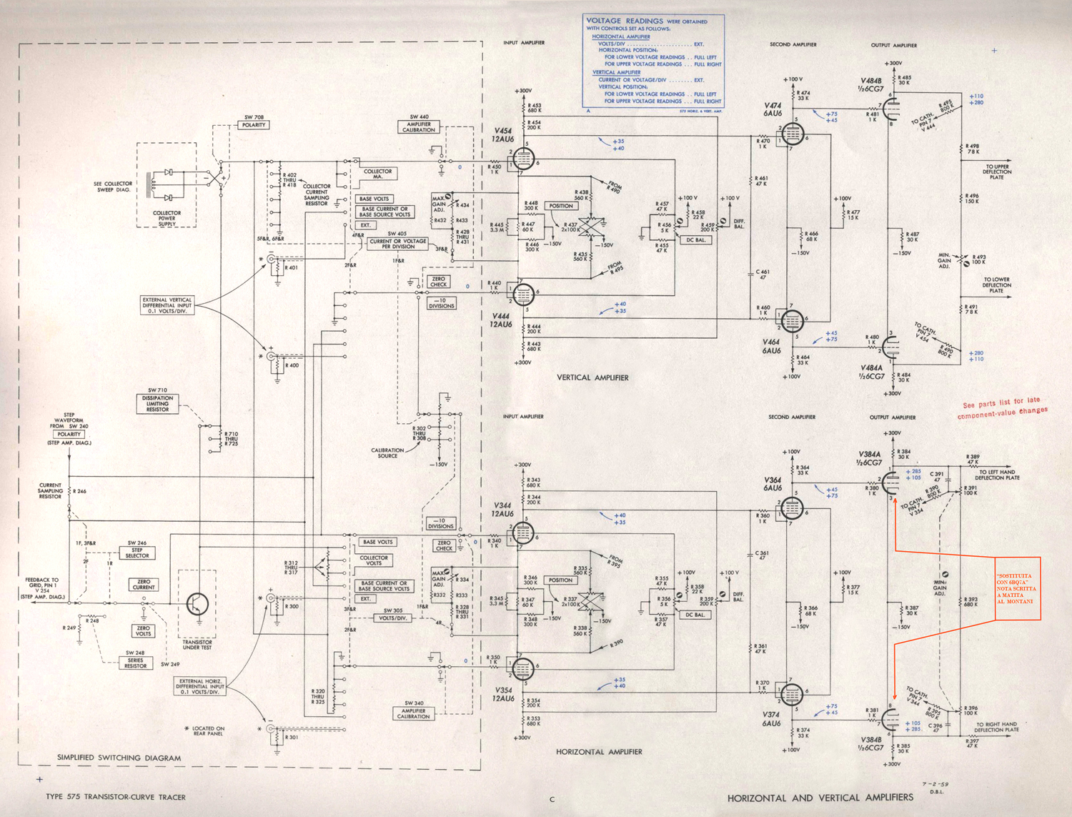
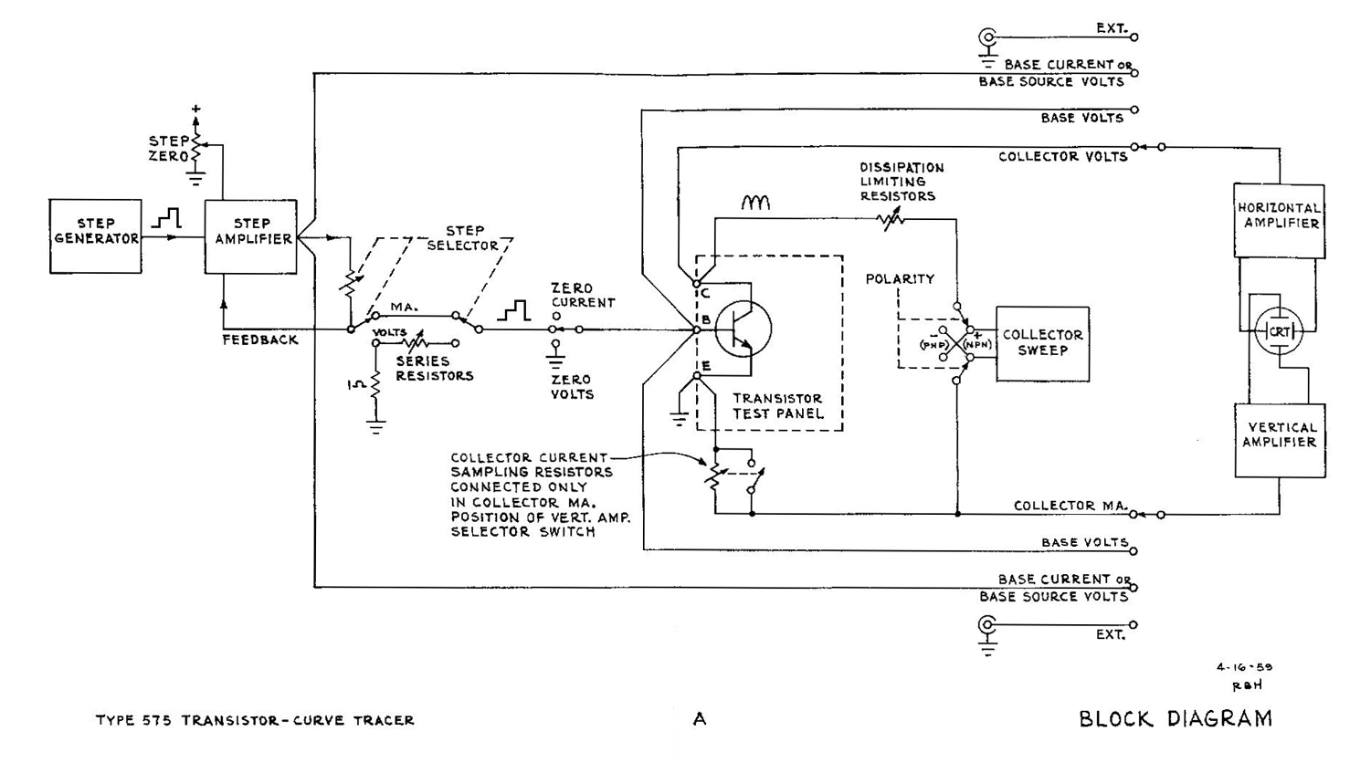
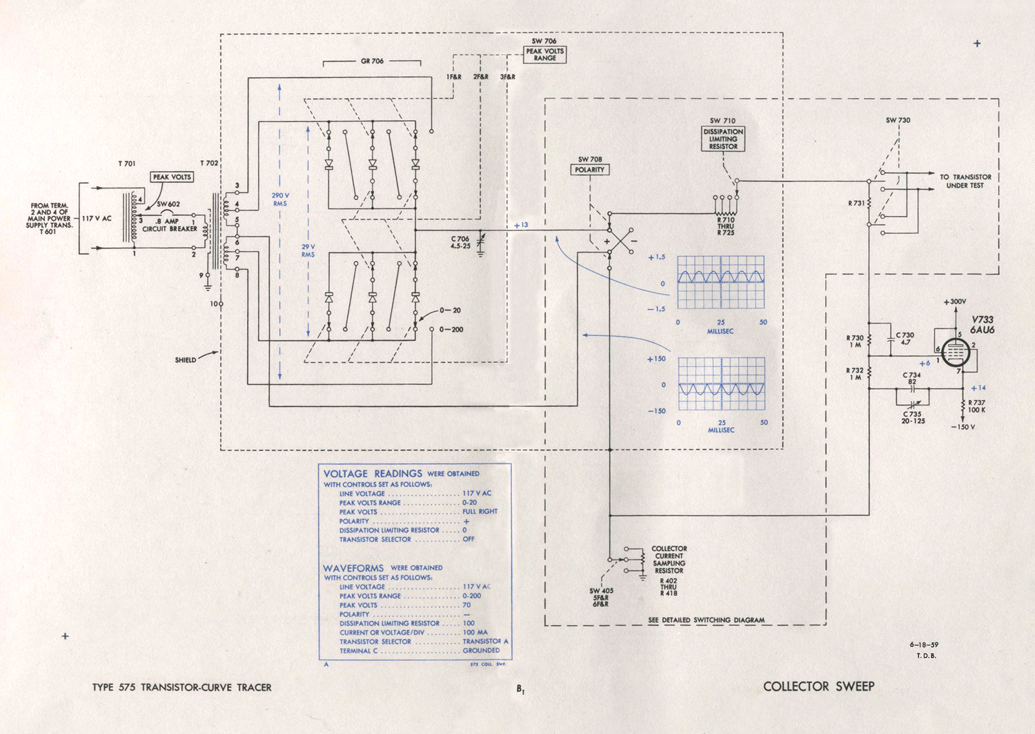
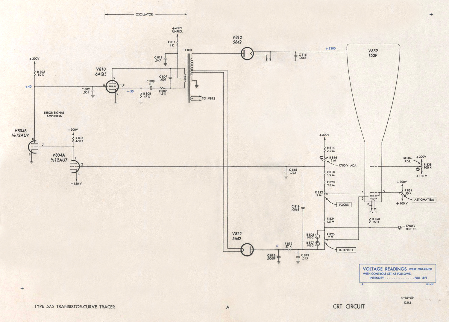
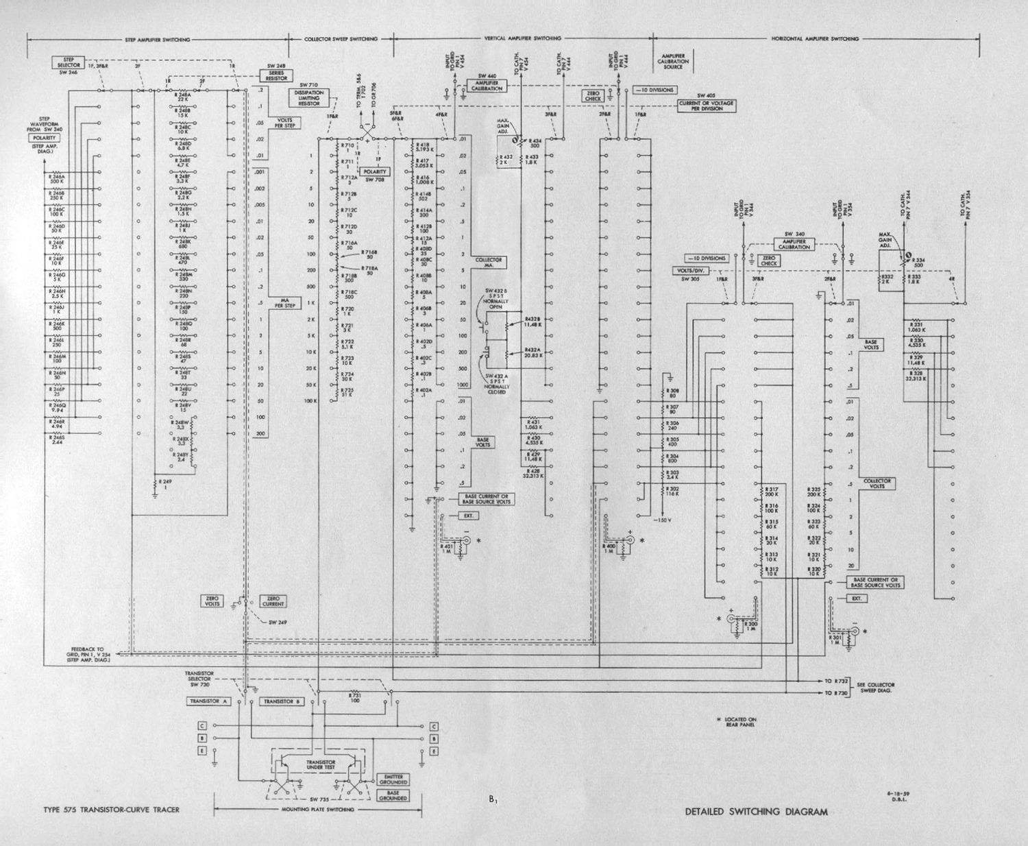
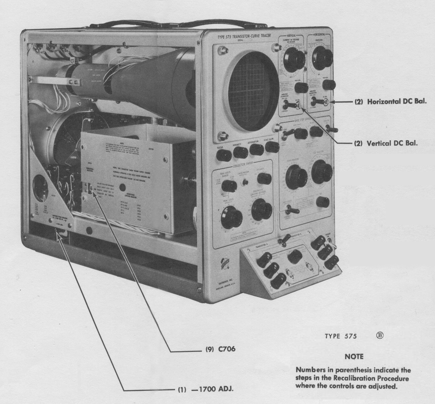
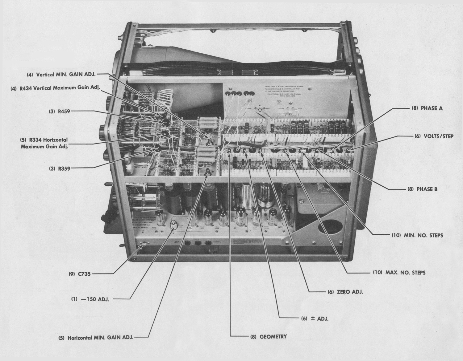
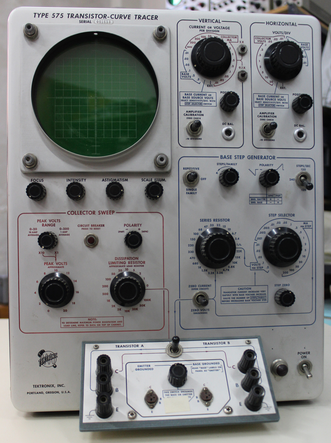
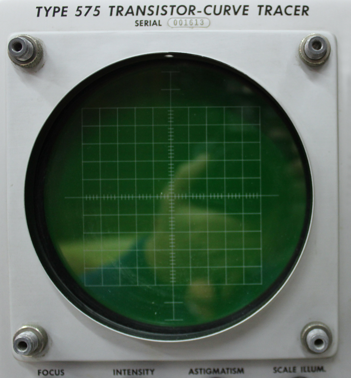
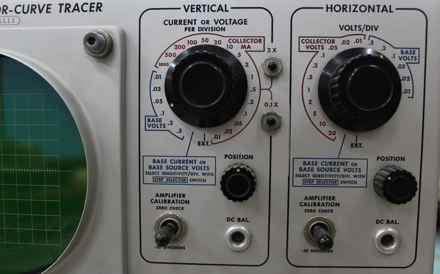
Transistor-curve tracer Tektronix type 575 serial number 001613 3ª parte.
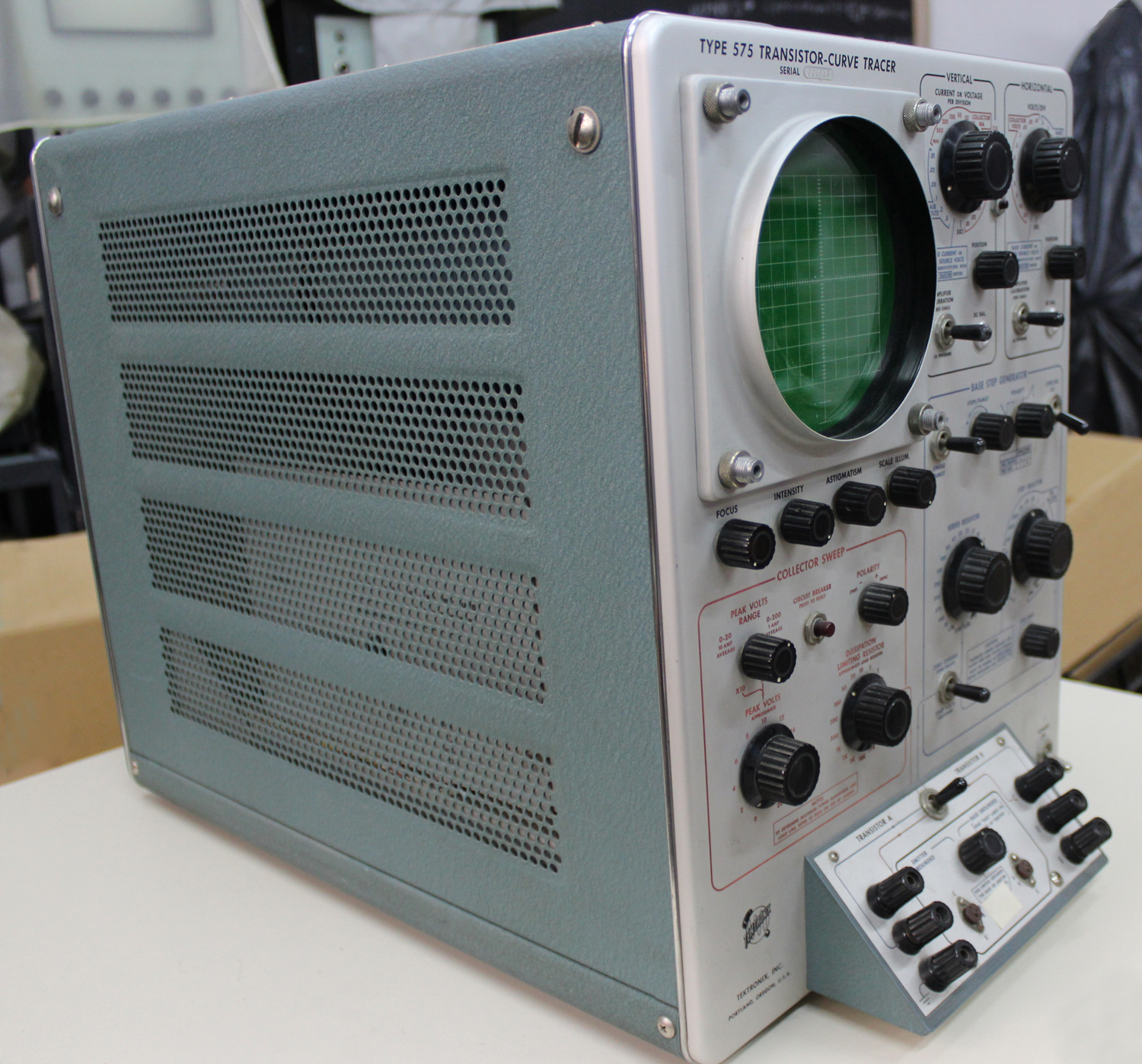 Transistor-curve tracer type 575, serial number 001613, Tektronix Inc. Terza parte.
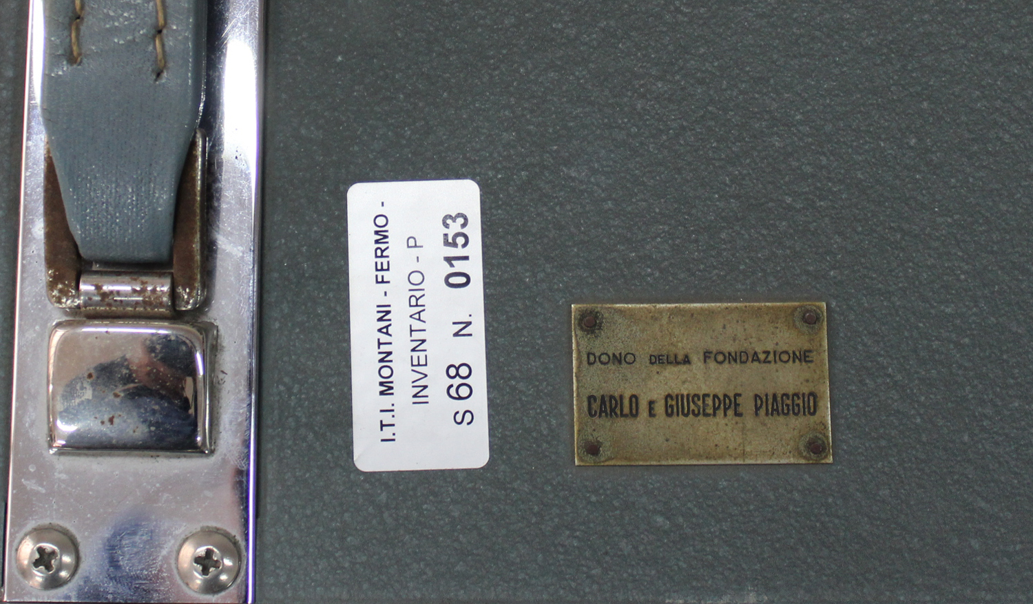
Dono della Fondazione Carlo e Giuseppe Piaggio, Genova.
Nell’Estratto dell’inventario del Laboratorio della Sezione Elettronica, in data giugno 1960 si fa corrispondere l’acquisto dell’oscilloscopio al numero D 1722 dell’inventario generale. Ma stranamente in quest’ultimo non si trova la solita corrispondenza, né c’è alcuna traccia dell’acquisto. Nell’Estratto si legge comunque: “Oscilloscopio modello 575 Tektronix”.
Nella Sezione Elettronica è conservato il manuale di istruzioni il cui testo è molto lungo, e non riteniamo che sia da riportare nelle tre schede dedicate a questo oscilloscopio poiché si trova all’indirizzo:
http://web.mit.edu/6.101/www/reference/tek_575_manual.pdf
Altri indirizzi utili sono:
pcbunn.cacr.caltech.edu/jjb/Tektronix/575/tek_575_use.pdf
http://web.mit.edu/6.101/www/reference/tek575.html
http://w140.com/tekwiki/wiki/575
Ci è sembrato comunque suggestivo riportare le numerose figure, che sono nel manuale, opportunamente elaborate per adattarle al sito.
Per consultare le altre due schede dedicate a questo oscilloscopio scrivere “575” su Cerca.
Foto di Claudio Profumieri. Elaborazioni, ricerche e testo a cura di Fabio Panfili.
Per ingrandire le immagini cliccare su di esse col tasto destro del mouse e scegliere tra le opzioni.
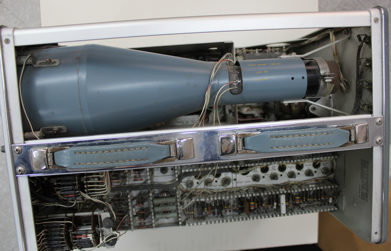
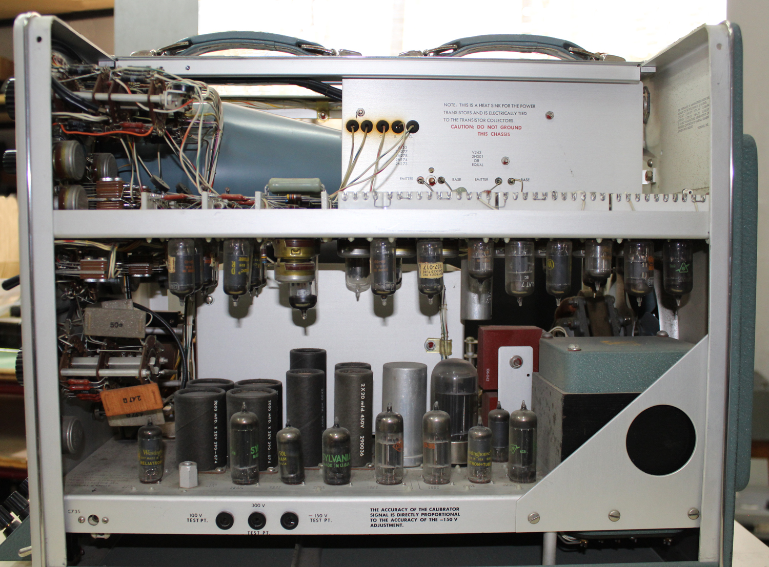
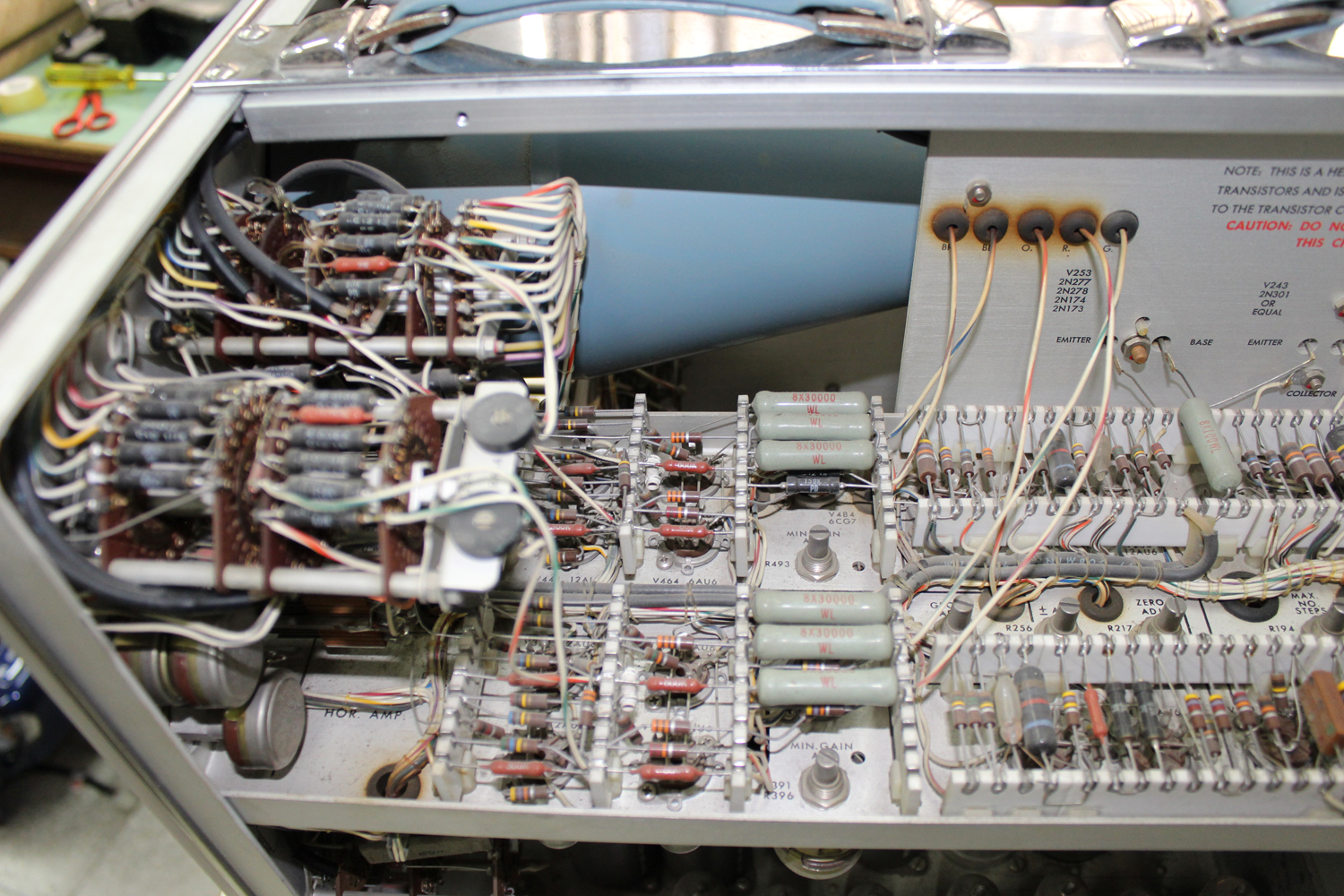
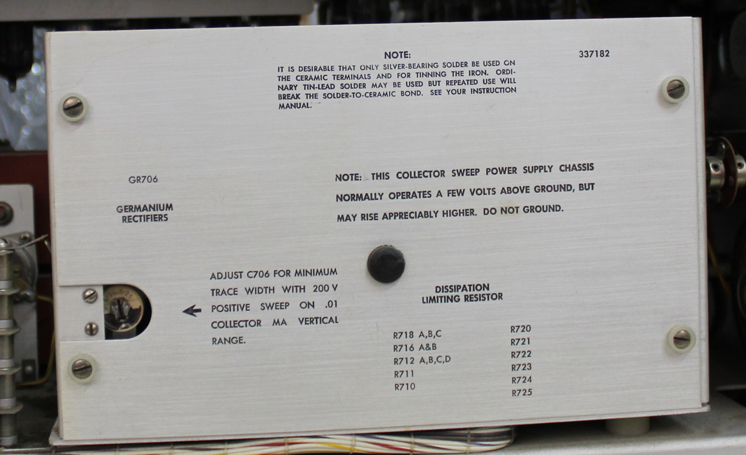
Transistor-Curve Tracer Tektronix type 575 serial number 001613 2ª parte
Transistor-curve tracer type 575, serial number 001613, Tektronix Inc. Seconda parte.
Dono della Fondazione Carlo e Giuseppe Piaggio, Genova.
Nell’Estratto dell’inventario del Laboratorio della Sezione Elettronica, in data giugno 1960 si fa corrispondere l’acquisto dell’oscilloscopio al numero D 1722 dell’inventario generale. Ma stranamente in quest’ultimo non si trova la solita corrispondenza, né c’è alcuna traccia dell’acquisto. Nell’Estratto si legge comunque: “Oscilloscopio modello 575 Tektronix”.
Nella Sezione Elettronica è conservato il manuale di istruzioni il cui testo è molto lungo, e non riteniamo che sia da riportare nelle tre schede dedicate a questo oscilloscopio poiché si trova all’indirizzo:
http://web.mit.edu/6.101/www/reference/tek_575_manual.pdf
Altri indirizzi utili sono:
pcbunn.cacr.caltech.edu/jjb/Tektronix/575/tek_575_use.pdf
http://web.mit.edu/6.101/www/reference/tek575.html
http://w140.com/tekwiki/wiki/575
Ci è sembrato comunque suggestivo riportare le numerose figure, che sono nel manuale, opportunamente elaborate per adattarle al sito.
Per consultare le altre due schede dedicate a questo oscilloscopio scrivere “575” su Cerca.
Foto di Claudio Profumieri. Elaborazioni, ricerche e testo a cura di Fabio Panfili.
Per ingrandire le immagini cliccare su di esse col tasto destro del mouse e scegliere tra le opzioni.
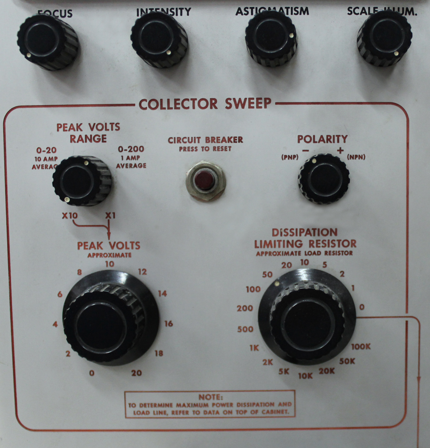
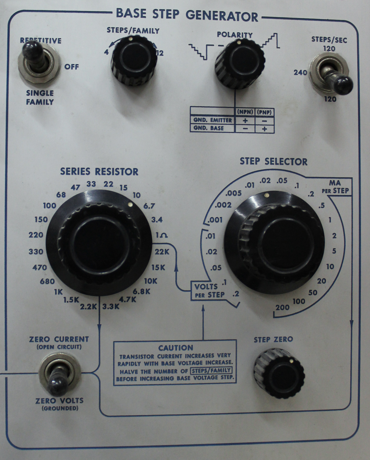
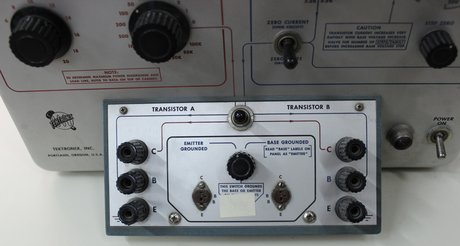
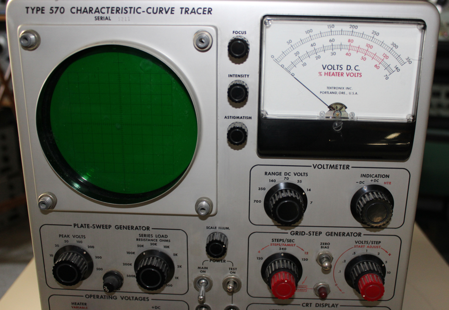
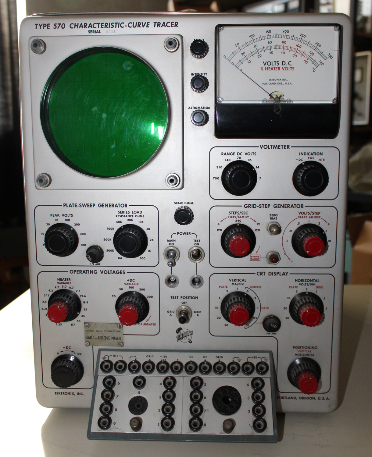
Caracteristic-curve tracer type 570, serial number 5211, Tektronix Inc. 2ª parte.
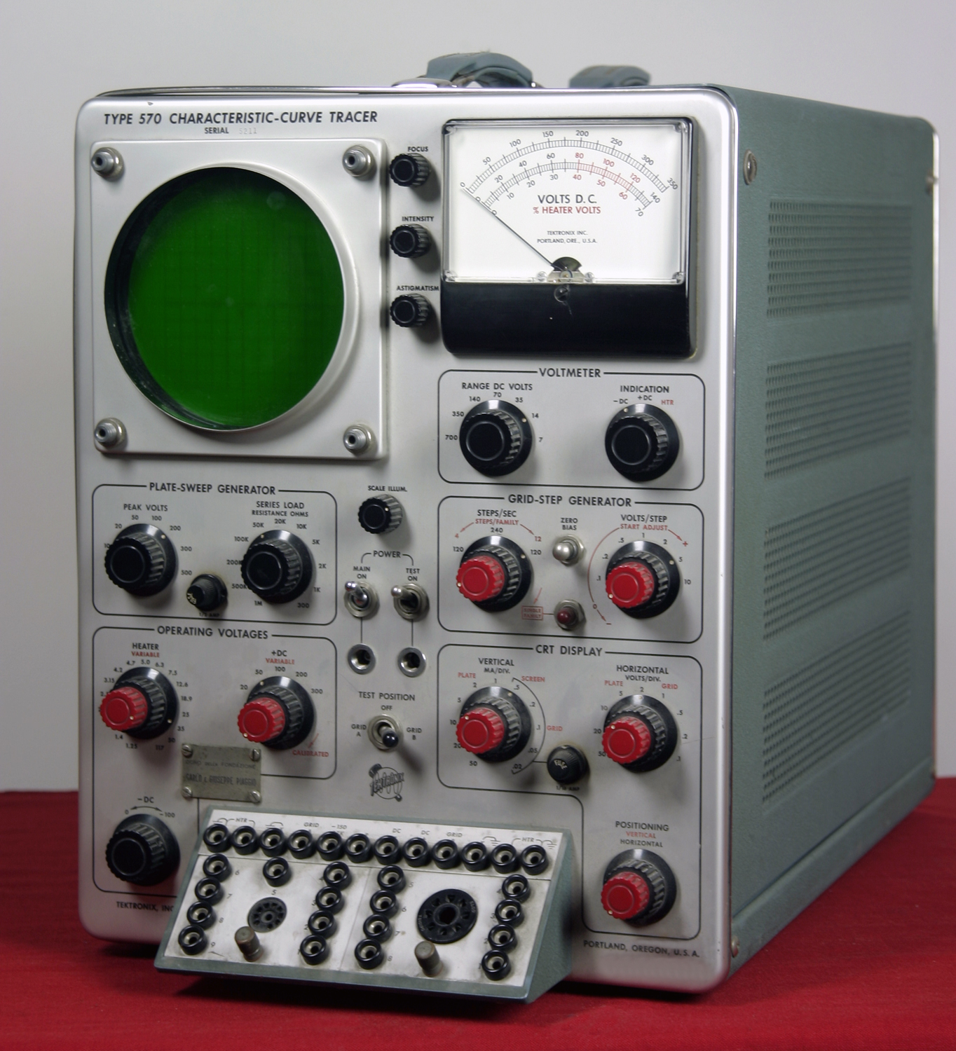
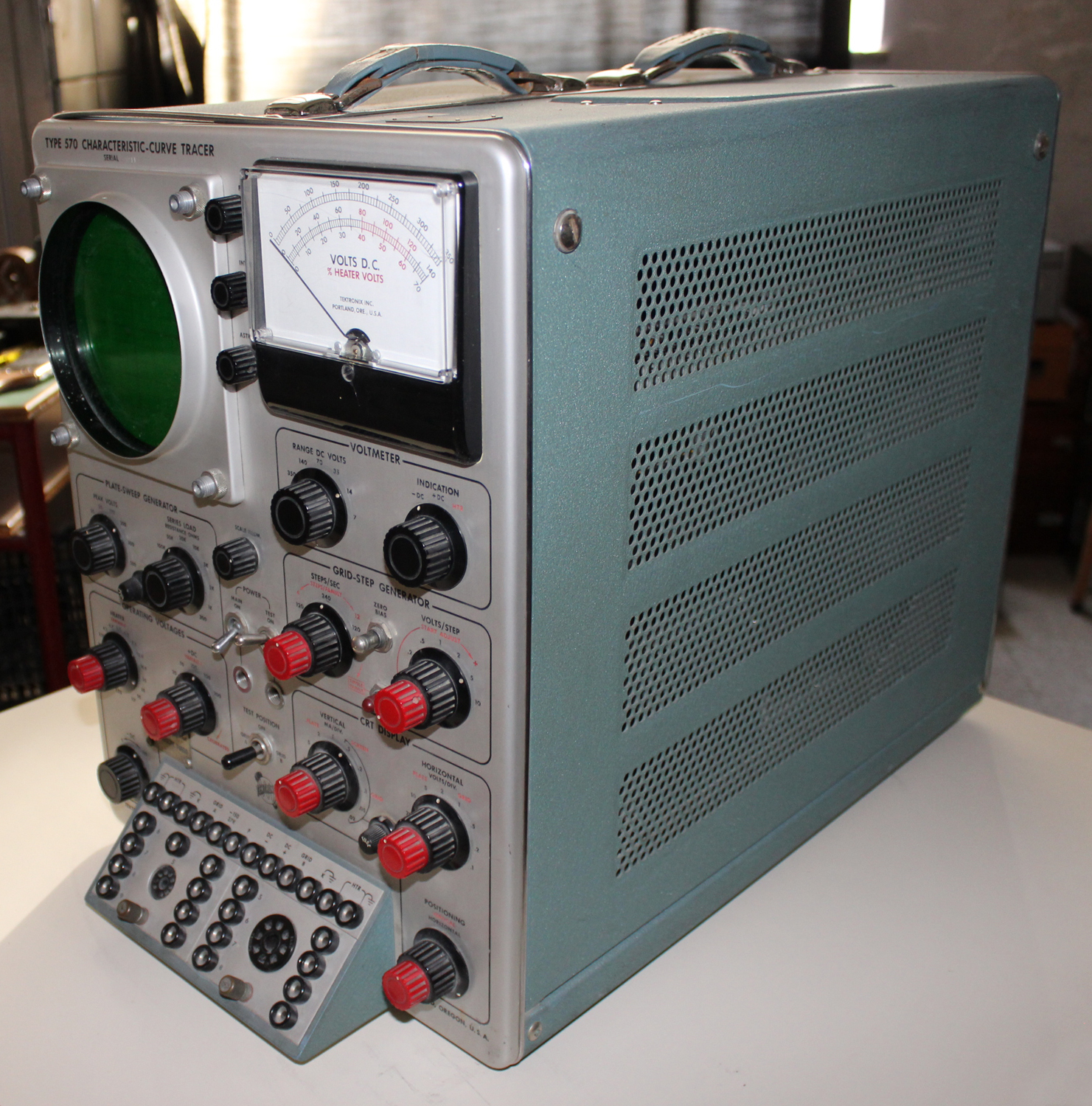 Caracteristic-curve tracer type 570, serial number 5211, Tektronix Inc. Seconda parte.
Dono della Fondazione Carlo e Giuseppe Piaggio, Genova.
Nell’Estratto dell’inventario del Laboratorio della Sezione Elettronica, in data giugno 1960 si fa corrispondere l’acquisto dell’oscilloscopio al numero D 1721 dell’inventario generale. Ma stranamente in quest’ultimo non si trova la solita corrispondenza, né c’è alcuna traccia dell’acquisto. Nell’Estratto si legge comunque: “Oscilloscopio modello 570 Tektronix”.
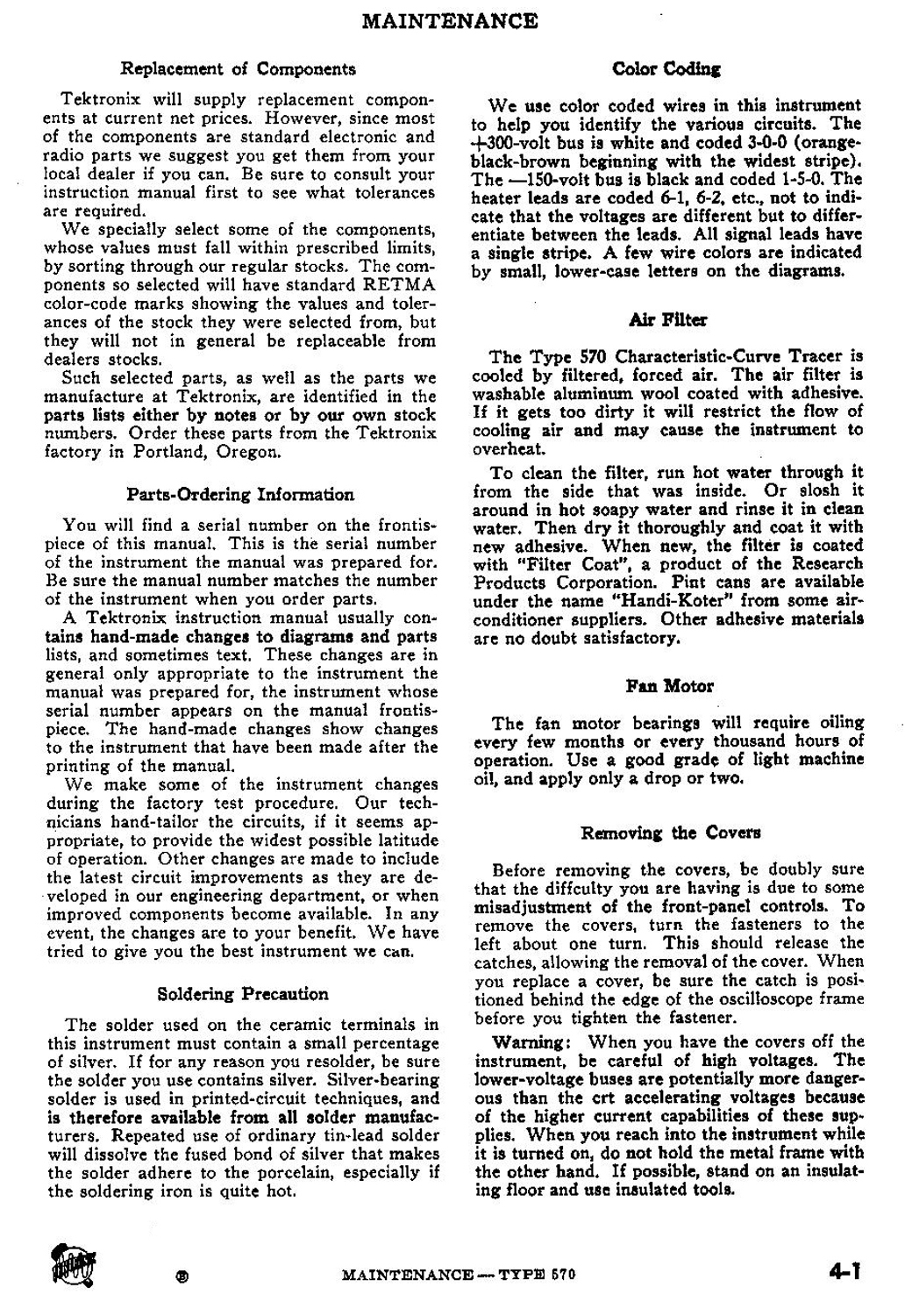
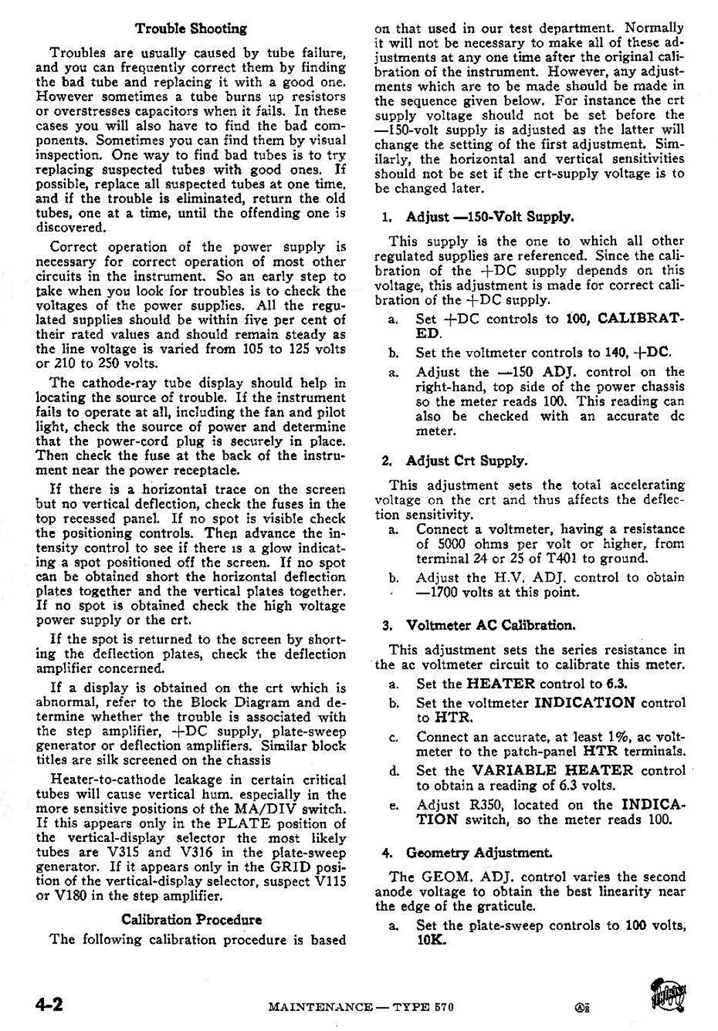
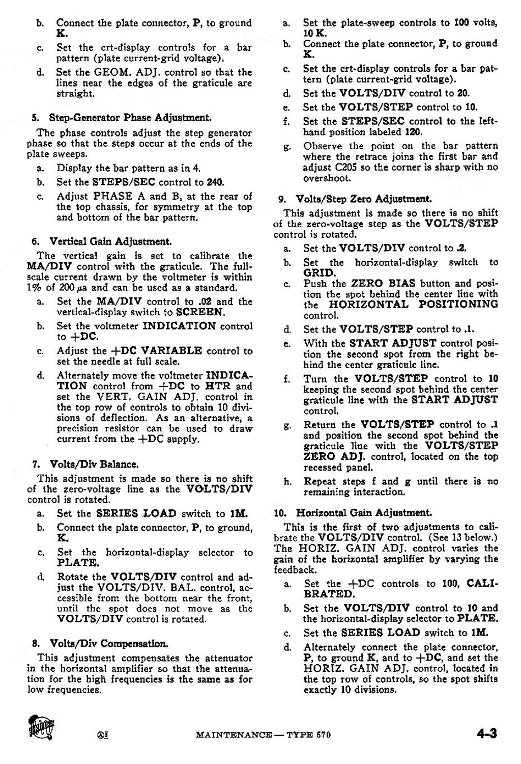
Nella Sezione Elettronica è conservato il manuale di istruzioni di cui riportiamo il testo diviso opportunamente in due parti. Inoltre pubblichiamo le pagine originali di MAINTENANCE in questa parte.
 §§§
§§§
«SINGLE-FAMILY DISPLAY
Characteristics of a tube in the region where its power rating is exceeded can be obtained by means of the single-family feature. When this feature is used, the grid is held negative until the SINGLE FAMILY button is pushed at which time it runs through one family of curves and again stops with the grid negative.
To use this feature, first set up the controls to plot a family of curves that is within the safe operating limits of the tube. Then turn the STEPS/FAMILY control clockwise to the stop. Make the desired changes to the operating and generator voltages. As these adjustments are being made push the SINGLE FAMILY button occasionally to determine the operating point that has been reached. When the desired operating point is reached push the SINGLE FAMILY button to obtain the single display.
The maximum voltage swing from the grid-step generator as it plots a family of curves and comes to rest is equivalent to about 14 steps at any setting of the VOLTS/STEP control. Thus, if the step generator is set for the maximum number of positive steps, it will rest five steps negative until the SINGLE FAMILY button is pushed. This will be between .5 volts and 50 volts negative depending on the setting of the VOLTS/STEP controls. In many cases this will not hold a tube cut off but it will usually be in a safe operating region. If the START AD-JUST control is backed off from its most positive position the voltage at which the grid rests can be increased up to a maximum of 140 volts negative.
The current ratings of the +DC supply and grid-step generator can also be safely exceeded by use of the single-family feature. The grid-step generator will deliver a peak current of from 200 to 250 ma if a few seconds are allowed between each presentation for the circuits to recover. The +DC supply will deliver 500 ma for a single family with a voltage drop of less than one volt. A second or two is required for the +DC supply circuits to recover before a second family can be plotted.
SEMICONDUCTOR DEVICES
The Type 570 was designed specifically for testing vacuum tubes. However, it is useful for plotting semiconductor diode characteristics and some transistor characteristics.
Semiconductor diode curves are plotted in the same way for vacuum tubes described under Thermionic Diodes. To protect the diode, maximum resistance consistent with adequate voltage swing should be used in the plate-sweep generator. If you connect the diode between the plate-sweep generator, P, and the +DC connector, be sure to load the +DC supply with an external resistor. This supply will lose regulation if current through the diode exceeds the current though the resistor by more than 2 ma. This resistor should be selected to draw 50 ma or less.
SPECIAL-APPLICATIONS
The Type 570 can he used to display the characteristics of special circuits and tubes. Resistors can be added between cathode and ground to show the effect of degeneration. Two triodes can be connected in a cascode circuit to obtain their characteristics in this connection. Similarly, two triodes can be cascaded although this connection may be less useful. Curves can be plotted of current versus voltage for gas diodes. For instance, in this way you can obtain the firing potential and voltage drop of a voltage reference tube. Other special applications may occur to you from time to time. Be sure to check the current requirements of a special circuit. The step generator, plate-sweep generator and +DC supply are designed for electron flow from ground into the supply only. A certain amount of current can be drawn from these supplies in the reverse direction but they quickly drop out of regulation. The amount of current which can be drawn in the reverse direction can be increased by appropriate external loads such as described under Thermionic Diode Curves.
OSCILLATION OF DISPLAY
Occasionally a tube will oscillate when placed in the test socket. This oscillation will be indicated on the screen by obvious oscillations or by unexplained discontinuities in the display. This will almost certainly occur if two tubes are connected in parallel. For this reason, parasitic-oscillation-suppression resistors have been built into special patch cords. Usually these resistors will prevent any oscillation if they are connected to the control grid of the tube under test. If these resistors are used, the effect of any grid current which may flow should be considered when evaluating the curves.
CIRCUIT DESCRIPTION
BLOCK DIAGRAM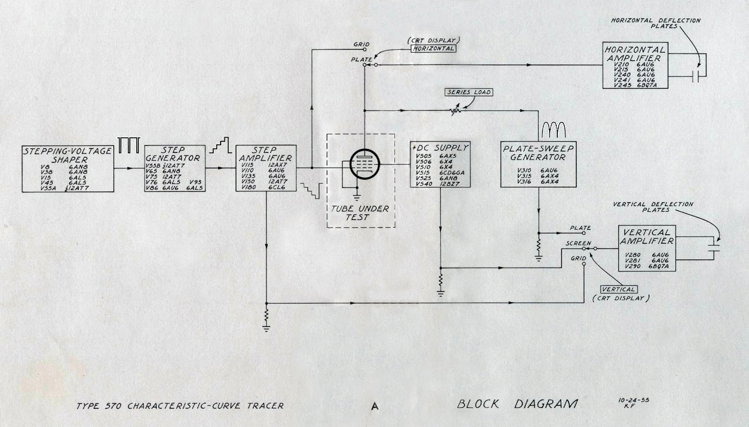
The Block Diagram shows interconnections of the functional parts of the instrument, except for the power supplies. Functions of the switches are shown instead of their actual connections.
Stepping -Voltage Shaper
The stepping-voltage shaper shifts the phase of the transformer waveform and shapes it to provide a current pulse of fixed amplitude to drive the step generator. This pulse occurs at a 120-cycle or 240-cycle rate as set by the STEPS/SEC control.
Step Generator
The step generator is a Miller integrator which receives the current pulse from the shaper and converts it to a voltage step. The step generator is controlled by a multivibrator which recycles it after a number of steps as selected by the STEPS/FAMILY control.
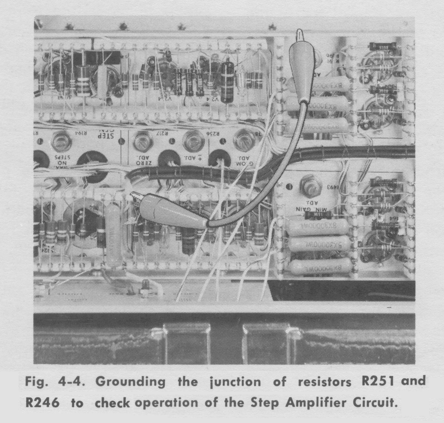
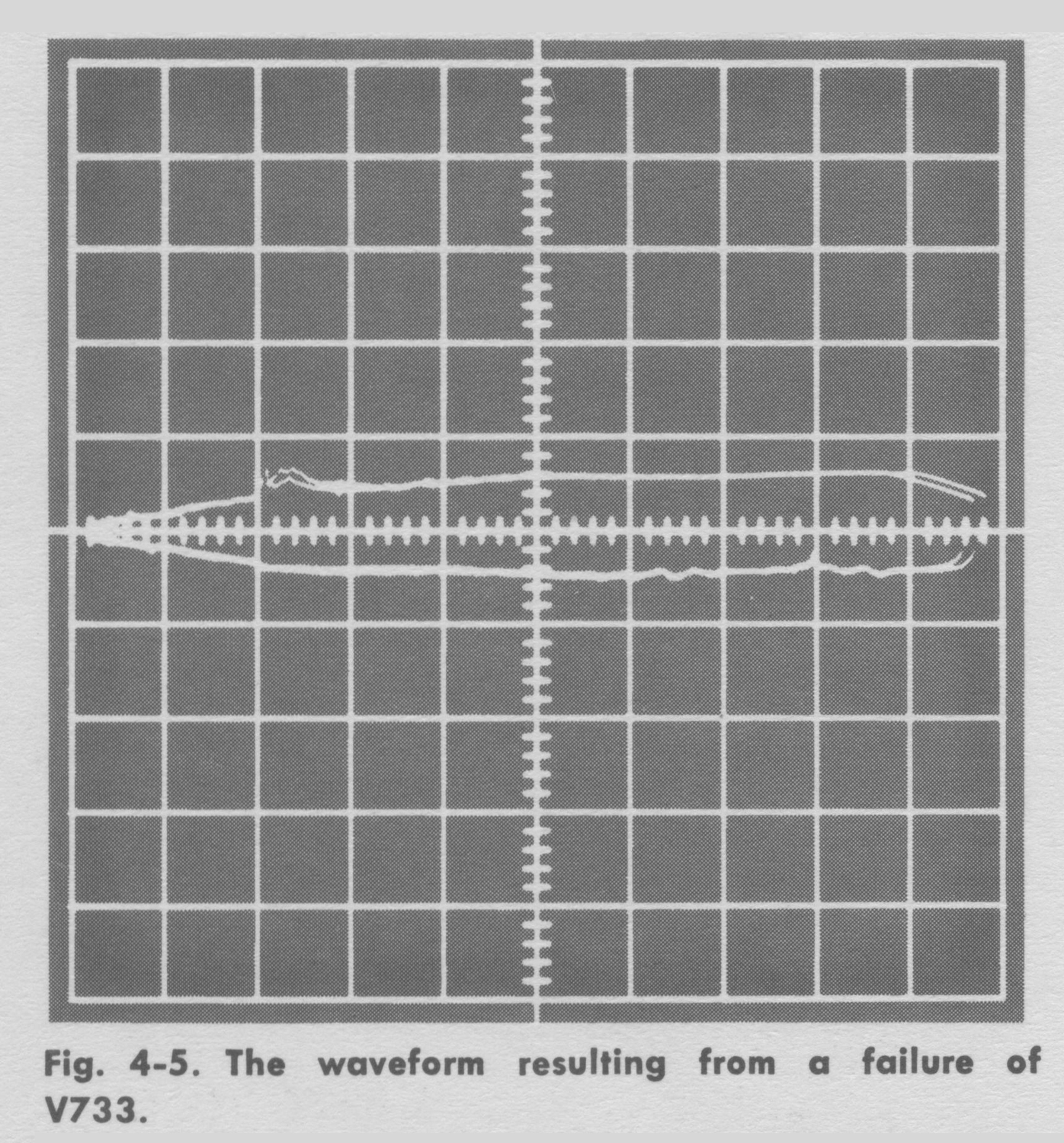
Step Amplifier
The positive-going waveform from the step generator is amplified and inverted by the step amplifier for application to the tube under test. Any current drawn from this amplifier by the tube under test is measured by the vertical amplifier in the GRID position of the vertical-display selector.
+DC Supply
The +DC supply provides a variable regulated voltage for application to the tube under test. Current drawn from this supply is measured by the vertical amplifier in the SCREEN position of the vertical-display selector.
Plate-Sweep Generator
The plate-sweep generator rectifies the transformer waveform to provide positive-goings weeps of plate voltage. Current drawn from this circuit is measured by the vertical amplifier in the PLATE position of the vertical display selector. The SERIES LOAD control selects the series resistance for the plate-sweep generator.
Horizontal Amplifier
The horizontal-display selector connects the grid or plate of the tube under test to the horizontal amplifier. The horizontal amplifier amplifies the signal and converts it for push-pull application to the deflection plates.
Vertical Amplifier
The vertical amplifier amplifies the signal selected by the vertical-display selector and applies it to the vertical deflection plates. For a more complete diagram of the vertical-display selector see the Vertical-Display Switching diagram.
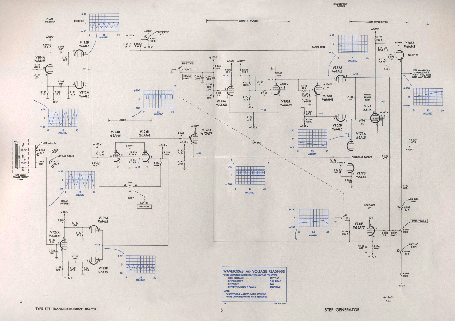
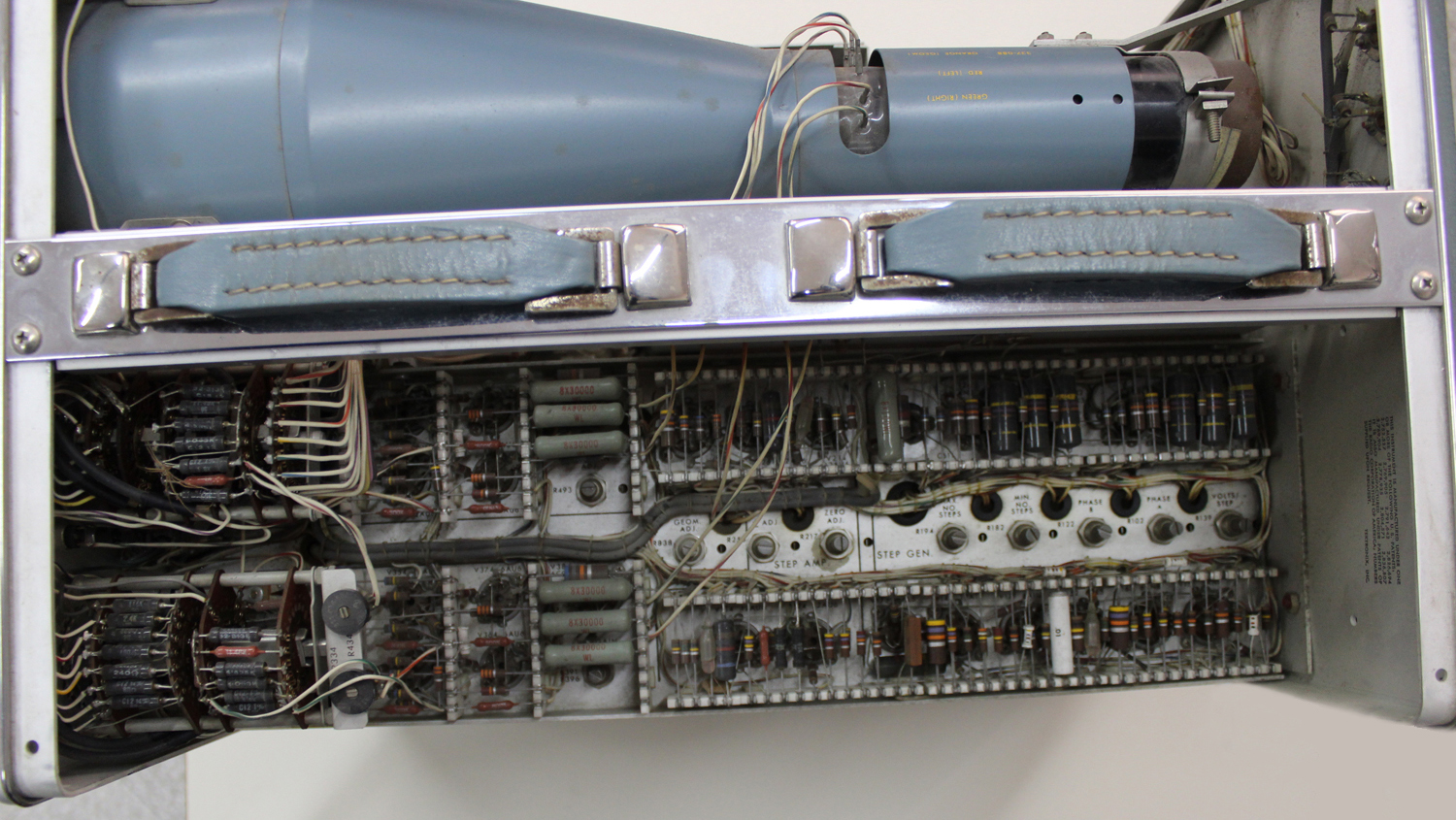
STEP-GENERATOR DIAGRAM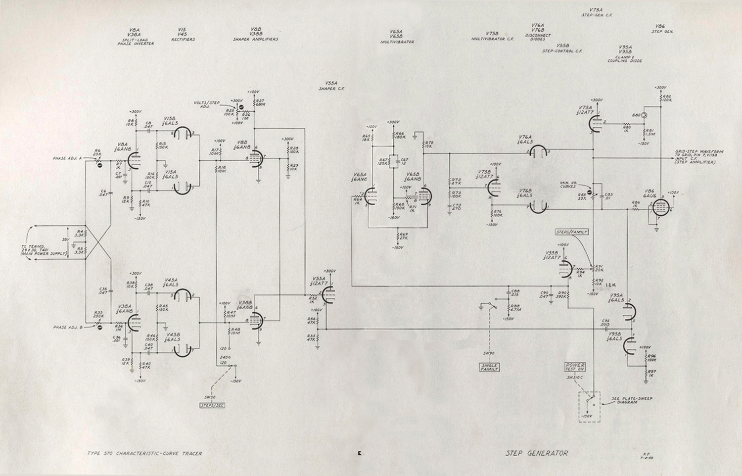
General
The Step Generator diagram includes the circuitry of the stepping-voltage-shaper and step-generator blocks in the Block Diagram.
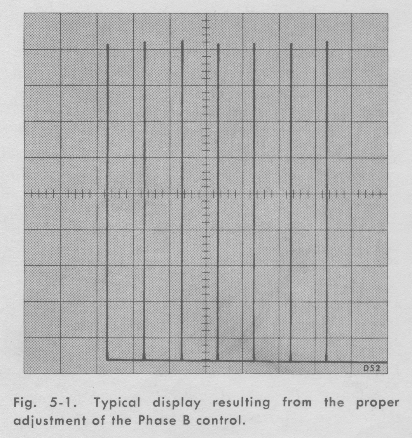
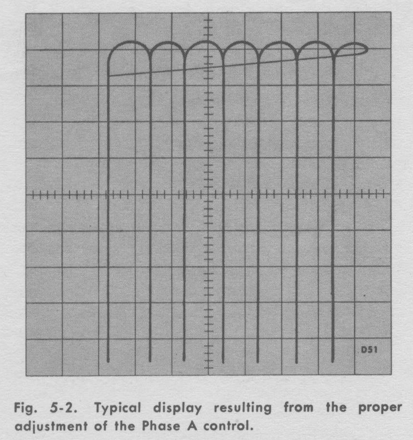
Phase Inverters
The main power transformer, T401, supplies 35 volts at line frequency to the phase-shifting networks, R6, C6 and R35, C35. PHASE ADJ. A has a small range of adjustment to permit this circuit to be adjusted to coincide with the phase of the plate-sweep waveform. PHASE-ADJ. B has additional range to permit its output to be set at 90 degrees with respect to the A circuit. V8A and V38A are split-load phase inverters with equal resistance in the plate and cathode circuits. The waveform at the plate is 180 degrees out of phase at the cathode. The dc component of the waveform is blocked by coupling capacitors, C8, C10, C38 and C40; and the waveform is rectified by full-wave rectifiers.
Shaper Amplifiers
The output from each pair of rectifiers is applied to a pentode amplifier. The rectifier output is a negative-going rectified sine wave of sufficient amplitude to hold the pentodes cut off except for short pulses as the grids approach ground potential. Since the pentodes have a common plate-load resistor, the pulses from both pentodes appear at the grid of the shaper cathode follower. The STEP/SEC switch biases one of the shaper amplifiers below cutoff in each of the 120 positions. This eliminates the corresponding pulses and reduces the stepping rate from 240 to 120 steps per second. The cathode of the shaper cathode follower, V55A, is held positive by divider R55 and R56. The grid of the cathode follower rests at a point selected by the VOLTS/STEP ADJ. control, R25, and a divider consisting of R26 and R27, when the shaper amplifiers are cut off. When the shaper amplifiers conduct the grid of the cathode follower is driven below plate-current cut off. The amplitude of the pulse from the cathode follower can therefore be closely controlled by the VOLTS/STEP ADJ. control.
Clamp and Coupling Diodes
The clamp and coupling diodes, V95A and B, differentiate the pulse from the shaper cathode follower. During the positive-portion of the pulse waveform the capacitor is charged through V95B. When the negative-going pulse occurs, this charge is released through V95A and adds to the charge in C85.
Step Generator
Because of their interdependence the multivibrator, disconnect diodes, step generator and associated circuitry will be considered at one time. To provide a starting place, single-family operation will he considered first.
For the single-family type of presentation the STEPS/FAMILY control, R91, is turned clock-wise so that the arm is at the most negative end of its range. In this condition, the voltage on the cathode of the step-control cathode follower, V55B, is sufficiently negative to hold one half of the multivibrator, V65A, cut off. The multivibrator consists of V65A and V65B in a dc-coupled circuit. In the quiescent state the grid of V65A is held at about -100 volts and the grid of V65B is at about -65 volts. V65B is conducting and its plate rests at -10 volts.
When the single-family button is pushed, C88 is discharged into C90 and the grid of V65A is raised so that V65A begins to conduct. The multivibrator switches so that V65A is conducting and V65B is cut off. The grid of V65A begins to go negative immediately as C90 loses the charge it received and the multivibrator returns to its quiescent condition. The result is a short positive pulse at the plate of V65B.
In the quiescent condition, the step generator tube, V86, is cut off. Its grid is held negative as a result of current flow through V95, V76B and cathode follower V75B. The grid of V75B is held at -10 volts by the multivibrator resulting in -8 volts on the grid of V86. The grid and cathode of V75A rest at about 200 volts as a result of the divider action of R81, B80, and R82. C85 is charged to about 210 volts.
The positive pulse from the multivibrator passes through the cathode follower, V75B, and diode V76B to raise the grid of V86 to ground potential. V86 conducts and its plate voltage drops cutting off cathode follower, V75A. C85 discharges through R85, R91 and R92 until clamped by V76A. When the multivibrator reverts, both diodes are cut off and the resistors R85, R91 and R92 tend to pull the capacitor and the grid of V86 negative. At this point the plate of V86 resumes control and any tendency of the grid to go negative is compensated by a rise in plate voltage. The step generator is now ready for its first step. The time required for the preceding operation after the SINGLE FAMILY button is pushed is less than the duration of one step.
The step is formed as follows: C95 has charged through V95B. When the negative pulse is applied to C95 it tends to pull the grid of V86 down with it. The rapid rise in the plate voltage of V86 is coupled back through V75A to C85. This reduces the voltage change on the grid to a very small step. The result is a step in the voltage across C85 as the charge from C95 is transferred to C85. Between pulses no current reaches the grid circuit and the output voltage does not change.
The steps are repeated for 12 or 13 steps at which time the plate of V86 loses control, the grid of V86 goes negative to plate-current cut off and the quiescent condition is reached. If the recurrent mode of operation is used, the arm of the STEPS/FAMILY control is set to a more positive position. The stepping waveform is developed across the divider consisting of R85, R91 and R92. As the waveform goes positive, a point will be reached where the voltage from the step-control cathode follower, V55B, is sufficient to switch the multivibrator. When this happens C85 is discharged and the step generator starts over again. R85 labeled MIN. NO. OF CURVES is normally adjusted so the step generator will have four steps when the STEPS/FAMILY control is counterclockwise.
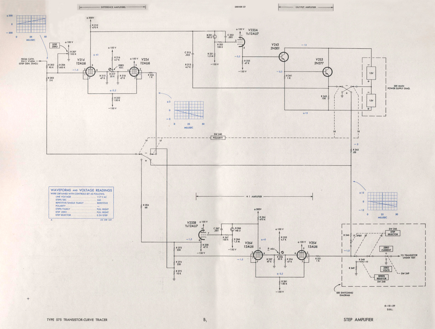
STEP AMPLIFIER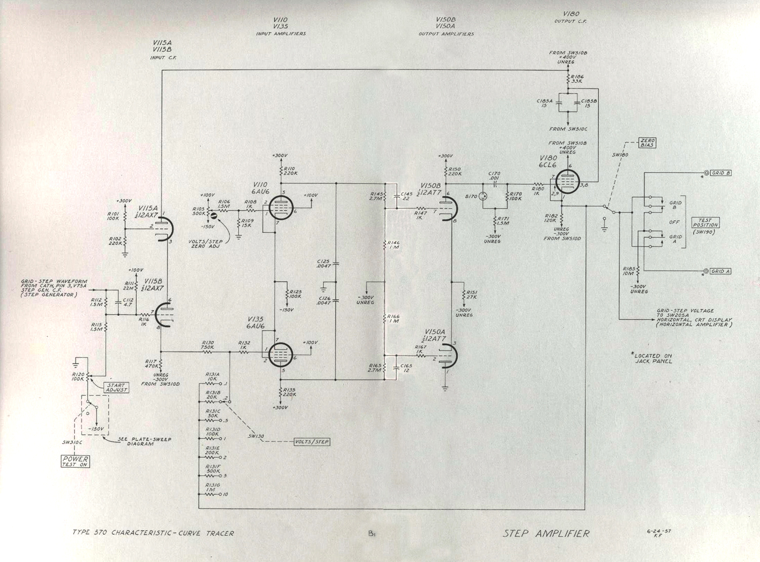 Input Cathode Follower
The incoming step waveform passes through a level-setting voltage divider, R112, R115 and R120, and into cathode follower V115B. V115A serves as a voltage regulator to regulate the voltage from the unregulated +400 volt supplies used for this stage.
Input Amplifiers
V110 and V135 are common-cathode, phase-splitter amplifiers. The VOLTS/STEP ZERO ADJ. control, R105, sets the level of the grid of V110 to balance the amplifier so the zero bias trace does not shift as the VOLTS/STEP control is rotated. C125 and C126 reduce the band-width of this stage to maintain stability with the large amount of feedback used.
Output Amplifiers
The output amplifiers, V150A and V150B, amplify the waveform and reconvert it to single-ended output. The network including the neon diode B170 reduces the dc level of the signal at the grid of V180 without attenuation of the signal.
Output Cathode Follower
The output cathode follower, V180, provides the necessary low impedance to drive the grid of the tube being tested. The ZERO BIAS switch, SW180, grounds the output to provide a zero-bias reference curve. The TEST POSITION selector connects the output of the step amplifier to either the GRID A or GRID B connector on the patch panel.
Volts/Step Control
The VOLTS/STEP control varies the amount of feedback and thus, the gain of the amplifier in seven fixed steps. This determines the grid-voltage change between the curves in the display.
Grid-Current Measurement
In order to measure grid current in the tube being tested, the grid current must flow through the current measuring circuits. Any current used to operate the step amplifier must be kept separate. To do this the output cathode follower is supplied with plate and cathode voltage from an ungrounded or floating power supply. The only path through which current will flow from ground into this power supply is from grid to cathode in the tube being tested and through the current-measuring resistors.
Since the input cathode follower is connected to the output cathode follower by the feedback resistors, it is connected to the floating supply also.
HORIZONTAL AMPLIFIER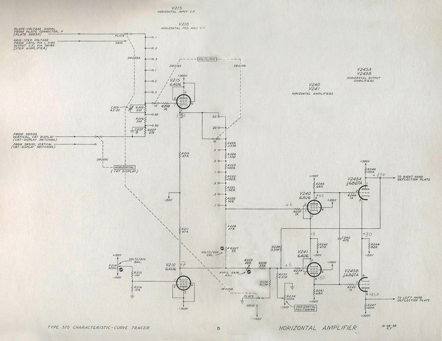 Volts/Div. Switch
The input cathode follower, V215, presents a high impedance to the circuits being measured and a low impedance to the part of the VOLTS/DIV switch in its cathode circuit. Part of the attenuation of the VOLTS/DIV switch is placed in the grid circuit so that the input voltage will not exceed the capabilities of the input cathode follower. This attenuator in the grid circuit is switched so that the current it draws will not be measured by the current measuring circuits in any position of the vertical-display switch.
The VOLTS/DIV BAL control R214, adjusts the dc level on the grid of cathode follower V210. This control is set so there is no shift of the zero-voltage line as the VOLTS/DIV control is rotated. The VOLTS/DIV CAL control compensates for the loading effect of the attenuator on the cathode follower.
Amplifiers
The first amplifiers, V240 and V241, are common-cathode, phase-splitter amplifiers. The bandwidth of this stage is limited by C242 for stability with feedback. The second stage,V245A and V245B, provides additional gain to drive the crt deflection plates. The HORIZ. GAIN ADJ. control adjusts the overall gain by varying the amount of feedback. The HORIZONTAL POSITIONING control positions the trace by varying the voltage on the grid at V241. One wafer of the horizontal display se- lector, SW205B, positions the beam to the right in the GRID position.
CRT-Display Switching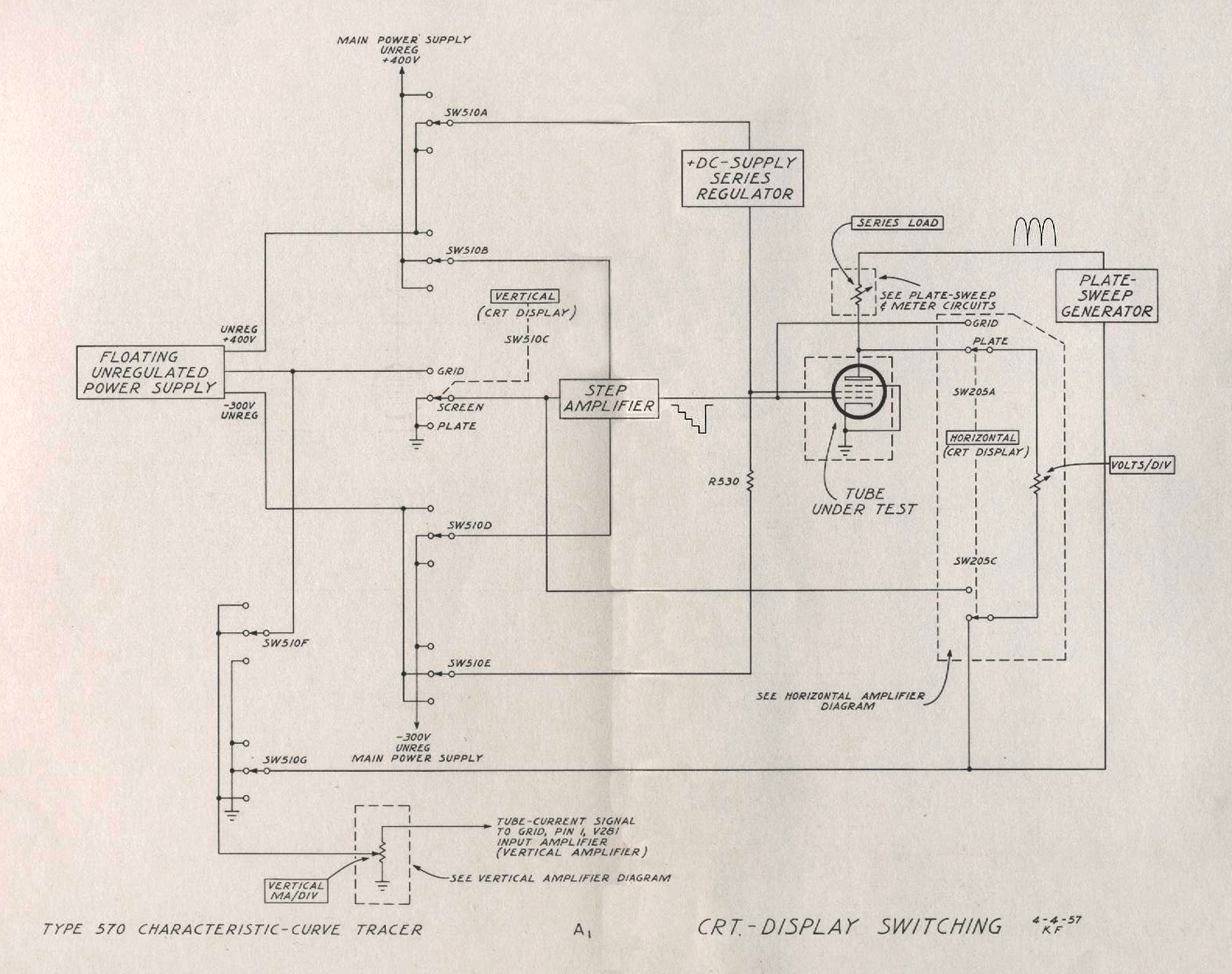
The CRT-Display Switching diagram shows the vertical-display switch in detail with the associated circuitry shown in block form. The horizontal-display switch and the VOLTS/DIV attenuator resistor are shown in the horizontal-amplifier block to show the path of the load current drawn by this resistor.
The floating, unregulated power supply shown at the left of the diagram is an auxiliary power supply. Its only return to ground is through SW510F which connects it to the current measuring resistors in the GRID and SCREEN positions of this switch.
In the GRID position of the vertical-display selector, this floating power supply is connected to the circuits in the step amplifier which supply current to the grid of the tube under test. In the SCREEN position of the vertical-display selector, this floating power supply is connected to the +DC-supply series regulator and the current which flows through the current measuring resistors is screen current. In the PLATE position of the vertical-display selector, the floating supply remains connected to the series regulator, but it is now disconnected from the current measuring resistors and grounded by SW510F.
The plate-sweep generator is also an ungrounded supply. It is connected to the current measuring resistors in the PLATE position of the vertical-display selector by SW510G. In the other two positions of this switch the plate-sweep generator is grounded.
The horizontal amplifier is connected to the plate or the grid of the tube under test by the horizontal-display selector. If the VOLTS/DIV attenuator resistor were grounded, current drawn by this resistor would pass through the current measuring resistors of the vertical amplifier. To avoid this, a section of the horizontal-display selector connects the ground return back to appropriate places on the vertical-display selector.
VERTICAL AMPLIFIER
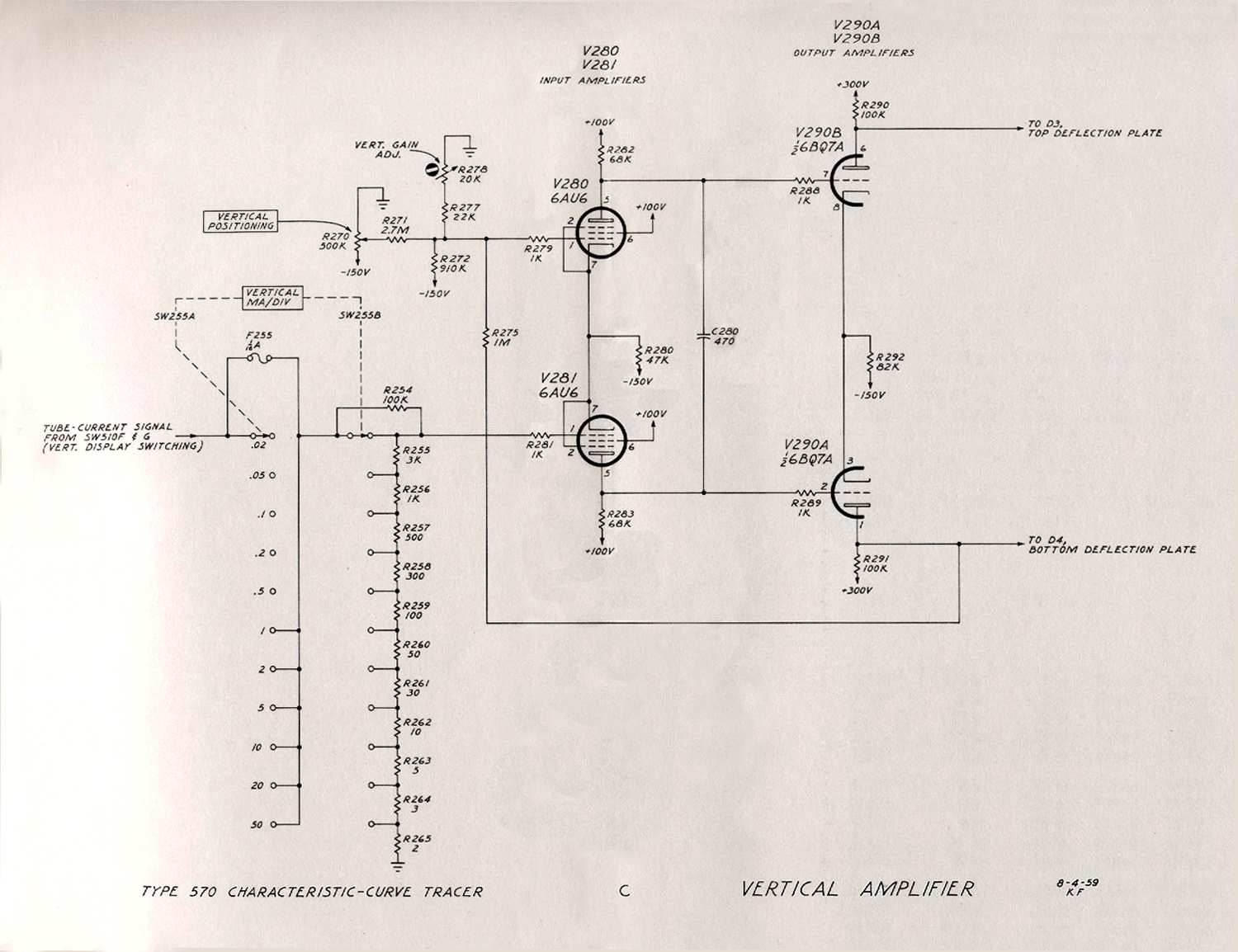
MA/DIV Switch
The VERTICAL MA/DIV switch selects the resistance to ground in the current measuring circuit and thus selects the sensitivity of the measurement. The grid of the input amplifier, V281, is connected to R255 instead of the arm of the switch to prevent any error that might be caused by contact resistance. R254 maintains a current path at all times as the switch is rotated between positions. Fuse F255 protects the high value resistors in the attenuator but is shorted out in the high-current positions of the switch.
Amplifiers
The input amplifiers, V281 and V280, are common cathode, phase-splitter amplifiers. R270 positions the crt display vertically by varying the voltage on the grid of V280. C280 limits the bandwidth of the input stage to maintain stability with the feedback used. The VERT. GAIN ADJ. control varies the gain by changing the amount of negative feedback. The output amplifiers provide the additional gain necessary to drive the crt deflection plates.
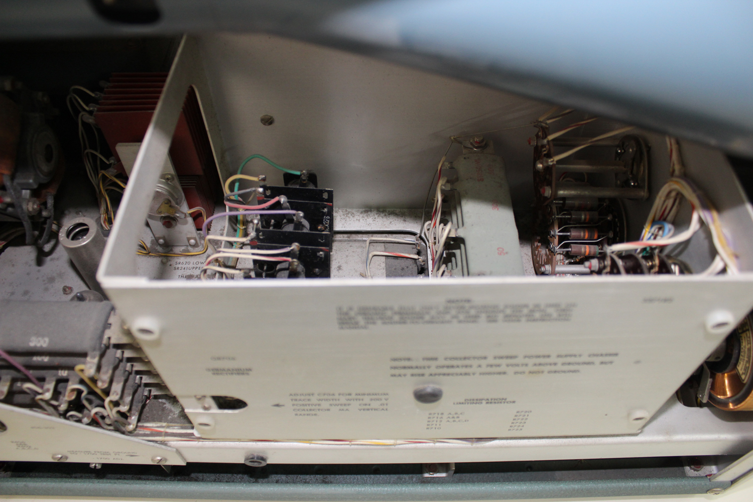
PLATE-SWEEP GENERATOR
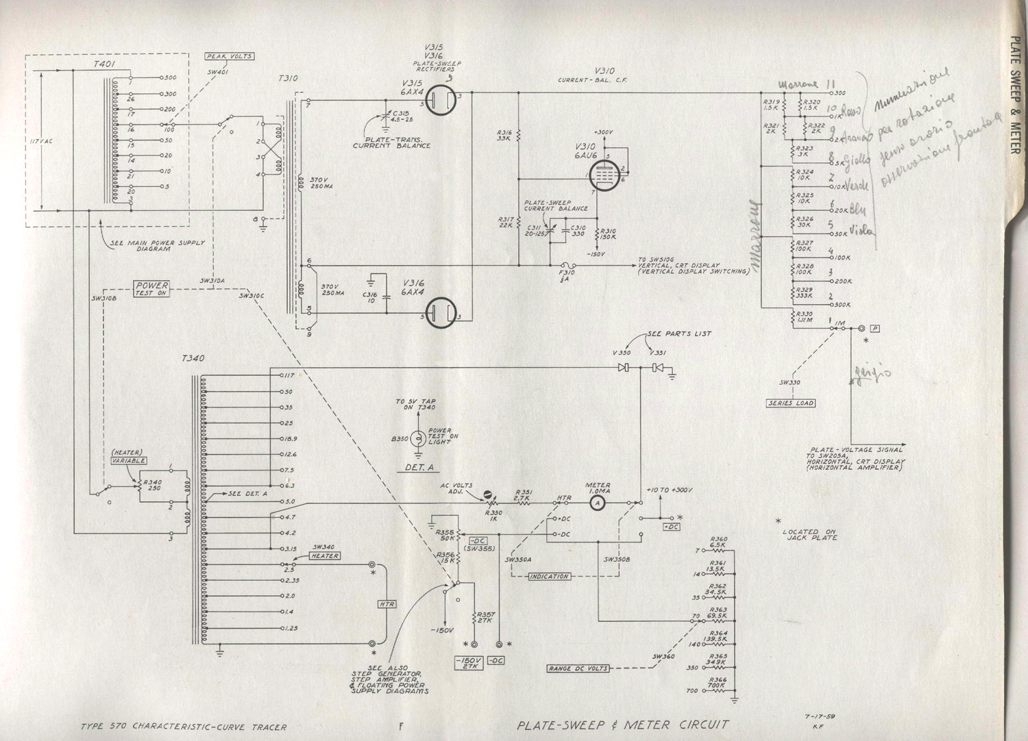
Transformer
The plate-sweep transformer, T310, is supplied from taps on the primary of the main power transformer, T401. Both primary and secondary windings are shielded to provide maximum control over capacitive currents. The PLATE TRANS. CURRENT BALANCE control, C315, balances the stray capacitances to ground associated with this winding. These currents would otherwise flow in the current measuring circuits.
Series Load Resistance
Full-wave rectification of the incoming sinusoidal waveform occurs in V315 and V316. The resulting waveform is applied to the plate of the tube under test by way of the SERIES LOAD switch. In the 300 ohm position of this switch, the transformer and rectifiers provide the resistance. Since the rectifiers are non-linear, this resistance varies from more than 300 ohms at low current to less than 200 ohms at maximum current.
Plate-Sweep Balance
The current-balance cathode follower compensates for capacitive current to ground in the SERIES LOAD switch and associated wiring. The plate sweep waveform is applied to the grid of the cathode follower by divider R316 and R317. Current is then added to the negative return lead by C310 and C311 which is opposite in phase to that drawn by the stray capacitance. C311 can be adjusted so no capacitive current flows in the current measuring resistors.
Voltmeter
The voltmeter consists of a 200 μA meter and associated multiplier’s. The INDICATION switch selects either the +DC, -DC or Heater supplies for application to the meter. The heater voltage is taken from fixed taps on the heater transformer and rectified in V350 and V351. The meter indicates heater voltage as a percentage of the voltage selected by the HEATER switch.
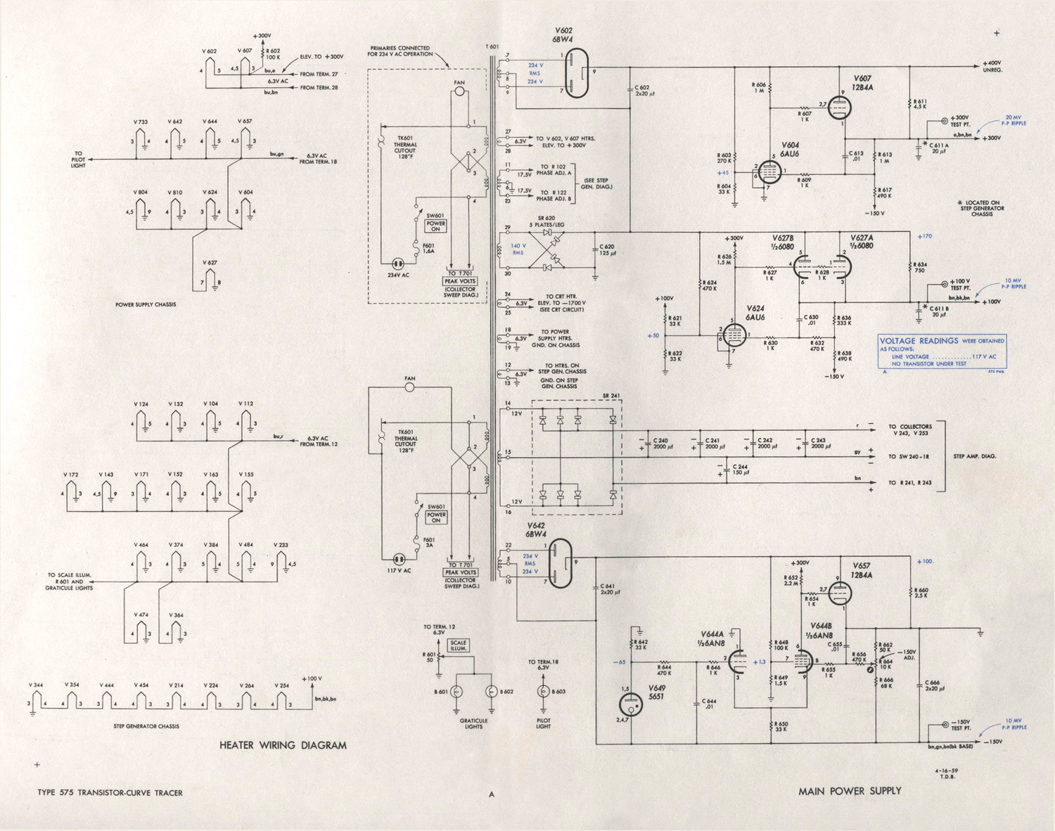
MAIN POWER SUPPLY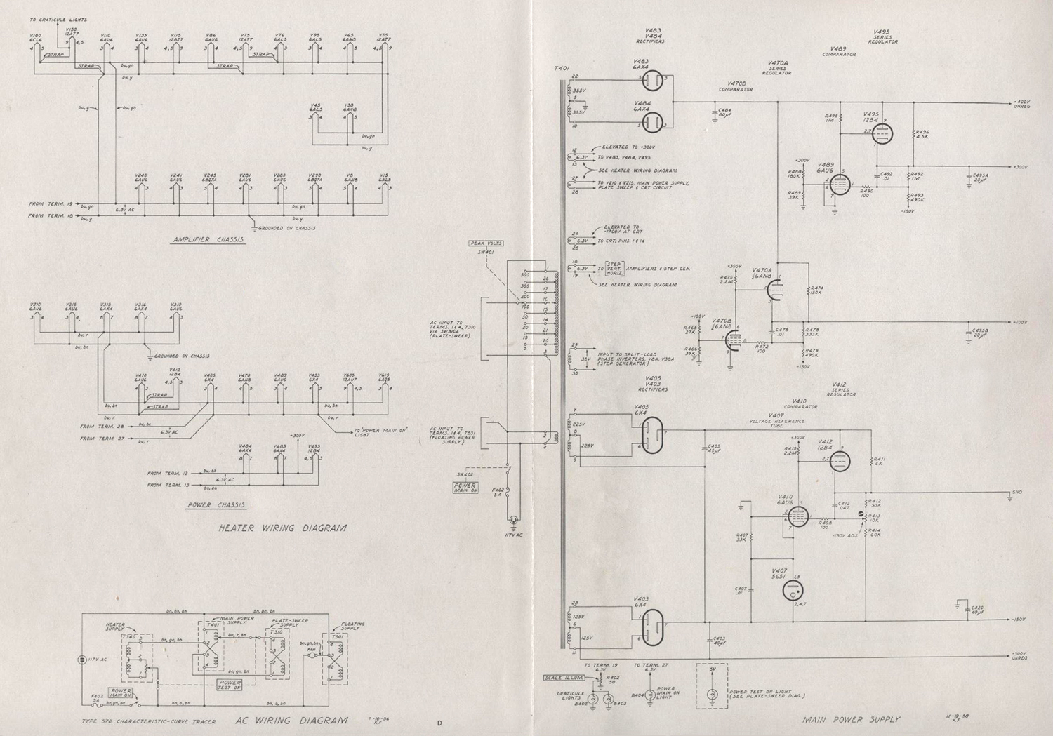 Transformer
The main power transformer, T401, supplies plate and heater power to all circuitry in the instrument except the floating supply tubes and circuitry. The two primary windings can be connected in series for 234-volt operation or in parallel for 117-volt operation. One primary winding is tapped to supply the voltages required by the plate-sweep transformer.
Negative Supply
Terminals 7 and 9 connect to V405 in a full-wave circuit to supply voltage to the negative voltage regulator. A gas-diode voltage-reference tube, V407, establishes the reference voltage for the regulator. This reference voltage is applied to the cathode of a comparator tube, V410, and compared with the voltage on a divider connected between the -150-volt bus and ground. R413, labeled -150 V ADJ., determines the percentage of voltage that appears at the grid of V410 and thereby determines the total voltage across the divider.
Any variation from the normal grid to cathode voltage on V410 appears as an amplified error signal at the plate. This error signal is applied to the grid of the series regulator tube, V412. This dc-coupled error signal controls the plate resistance of the series regulator tube changing it in the right direction to compensate for any change in output voltage. C412 increases the ac gain of the feedback loop to reduce the ripple. V403 is connected in a full wave circuit with its output added to the -150-volt supply to provide a 300-volt unregulated supply. This supply is used to supply other regulators or circuits which are insensitive to voltage variations.
Positive Supplies
V483 and V484 supply +400 volts, unregulated, to the positive-voltage regulators and other circuits which are insensitive to voltage variations. The -150-volt supply is used as the reference voltage for the positive-supply regulators. In the +300-volt regulator, the voltage at the tap on the divider, R492, R493, between +300 volts and -150 volts is compared with ground potential in V489. The amplified error signal is applied to the series tube, V495. R496 reduces the current through the series tube. C492 increases the high-frequency gain of the feedback loop.
The +100-volt regulator is similar to the +300 volt regulator, with V470B as the comparator tube and V470A as the series regulator.
FLOATING POWER SUPPLY
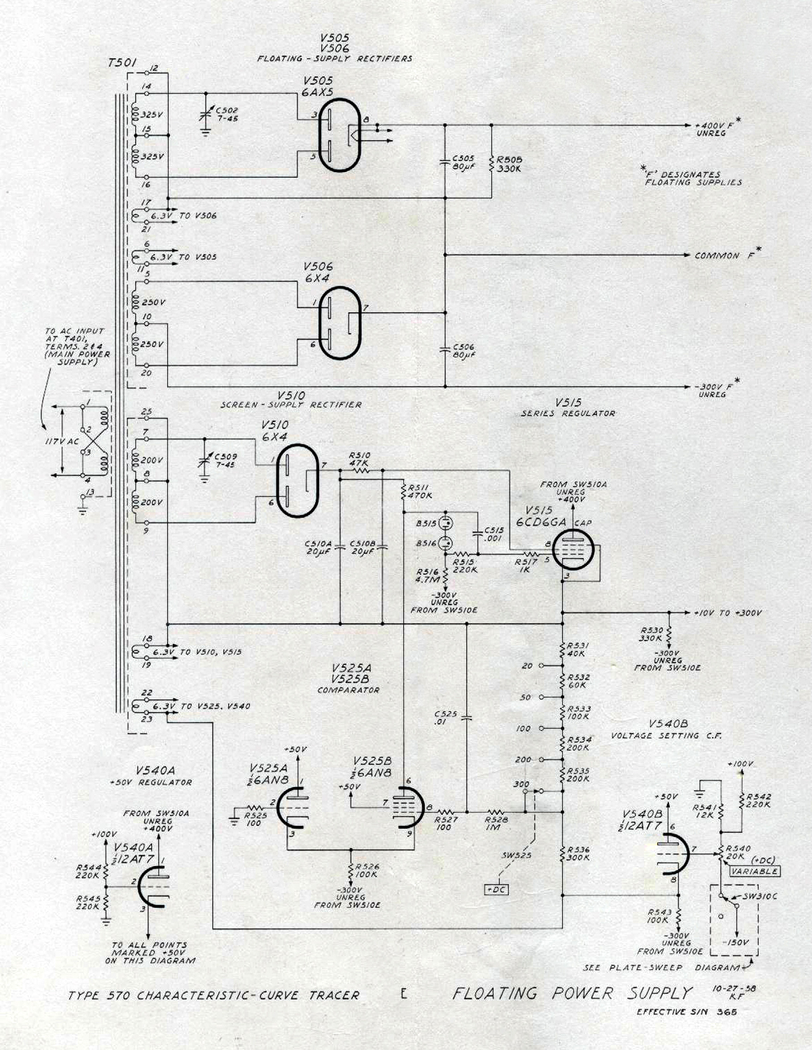
Transformer
Transformer T501 supplies plate and heater voltage for the floating power supply and regulator. Shields are used around the primary winding, the floating supply winding and the regulator circuit windings to minimize the effects of capacitive currents.
Rectifiers
V505 and V506 supply +400 volts and -300 volts with respect to the common lead. This supply is sometimes grounded directly and at other times connected to the current-measuring resistors as shown on the CRT-Display Switching diagram. C502 balances the stray capacitive current to ground so that this current does not flow through the current measuring resistors.
Regulator
The +DC-supply regulator receives +400 volts and -300 volts, unregulated, from either the main power supply or the floating power supply. This is determined by the setting of the horizontal-display switch shown in the CRT-Display Switching diagram. The output of the regulator is variable from 10 to 300 volts.
Screen voltage for the series regulator tube, V515, is obtained from the full-wave rectifier, V510. C510A and C510B with R510 reduce the ac ripple on the screen. The negative side of the supply is tied to the cathode of V515 so that the screen to cathode voltage remains the same as the output voltage is changed. C509 balances the capacitive current to ground in the screen supply. Reference voltage is obtained from the -150-volt supply. V540B isolates the reference voltage supply from the regulator so that no current will flow between the two circuits. VS25A and VS25B are comparator tubes. The voltage at a tap on the divider between the output of the regulator and the reference voltage is compared with ground potential. The amplified error signal at the plate of V525B is applied to the grid of the series tube, V515. B515 and B516 reduce the dc level of signal at this grid without attenuation of the signal.
The +DC switch changes the divider ratio in the divider at the grid of the comparator tube, V525B. The VARIABLE +DC control changes the reference voltage at the bottom of this divider. These two controls provide continuous variation of the output of the regulator from 10 volts
to 300 volts.
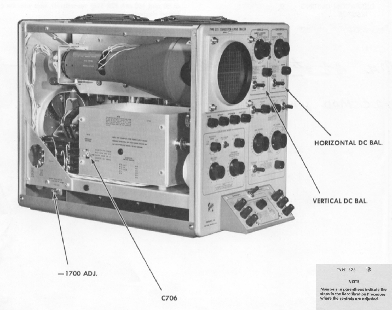
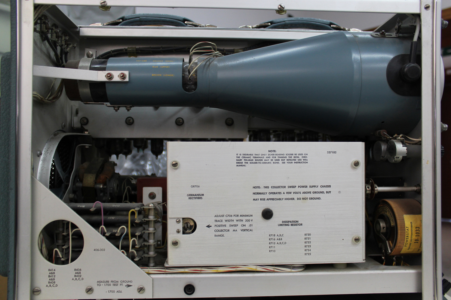
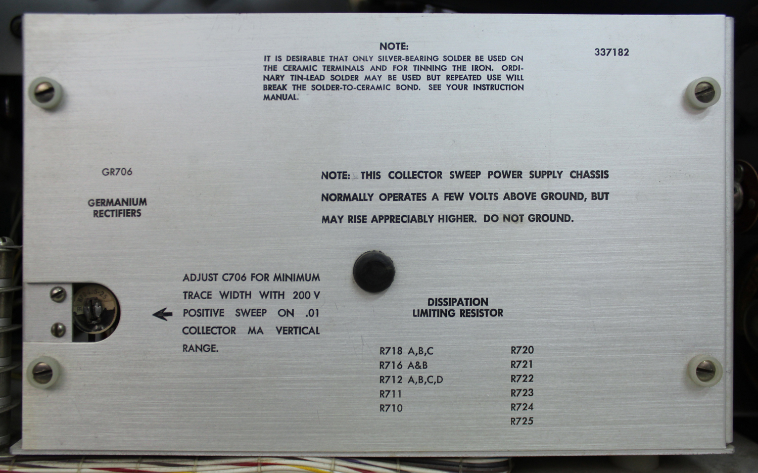
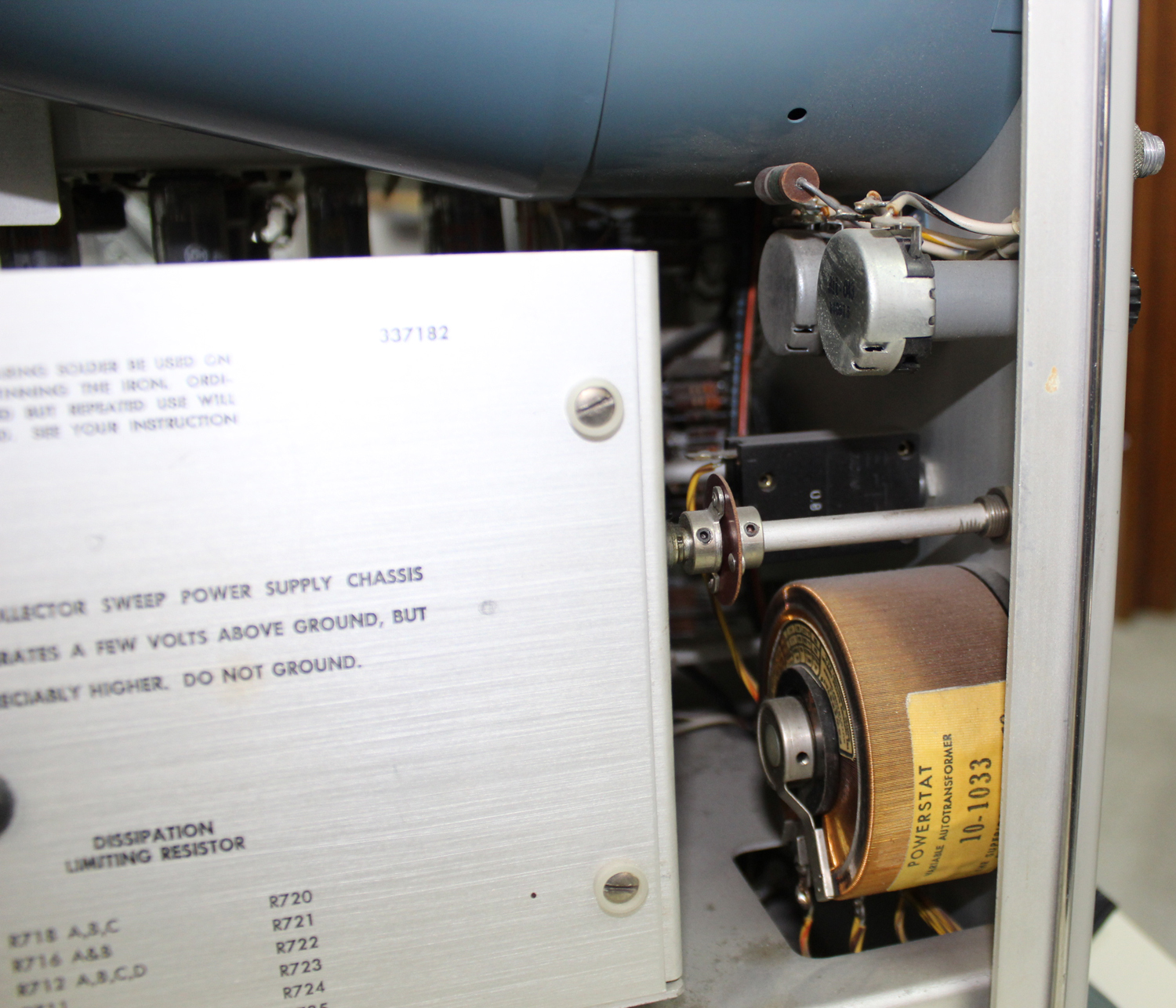
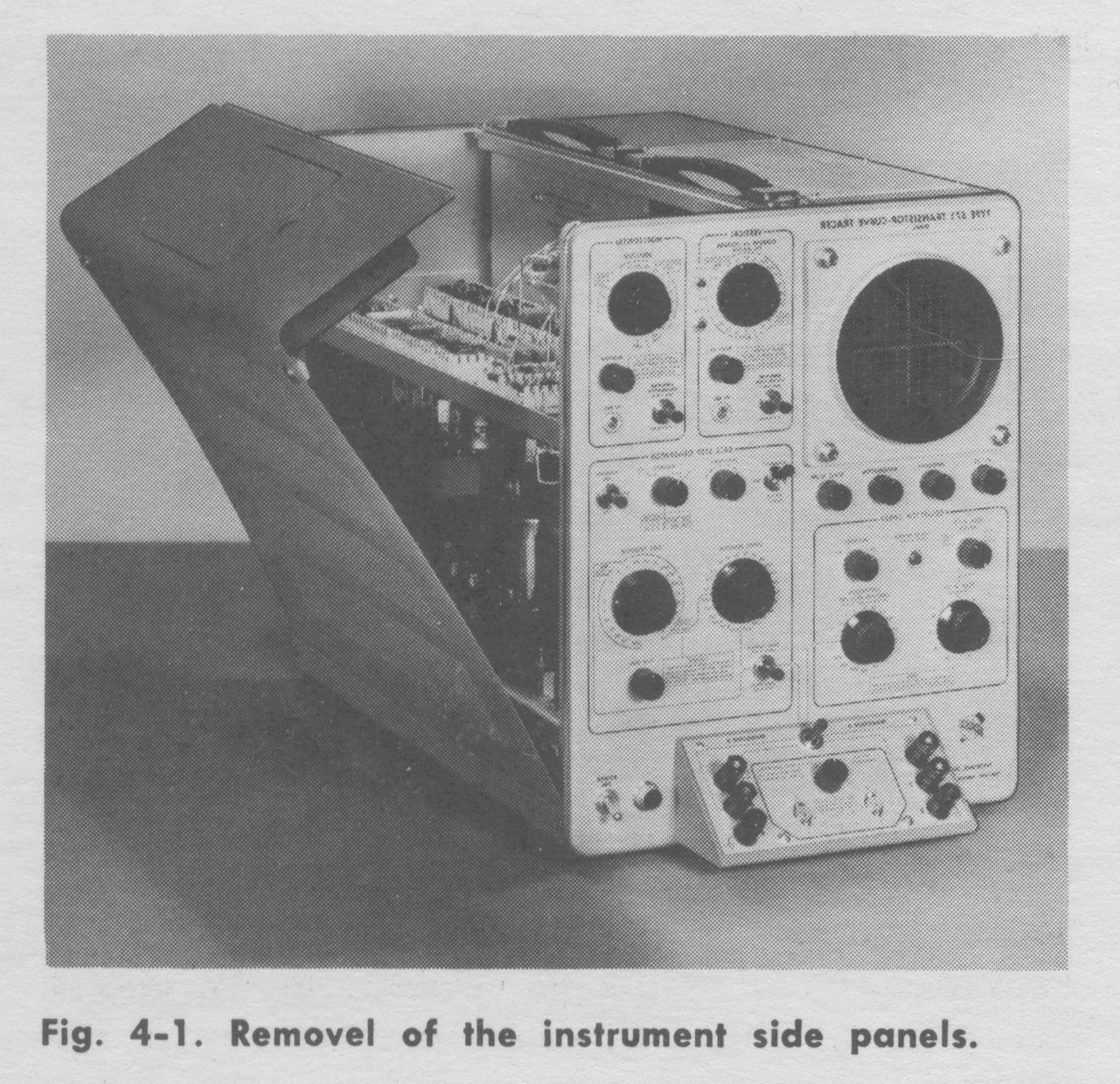
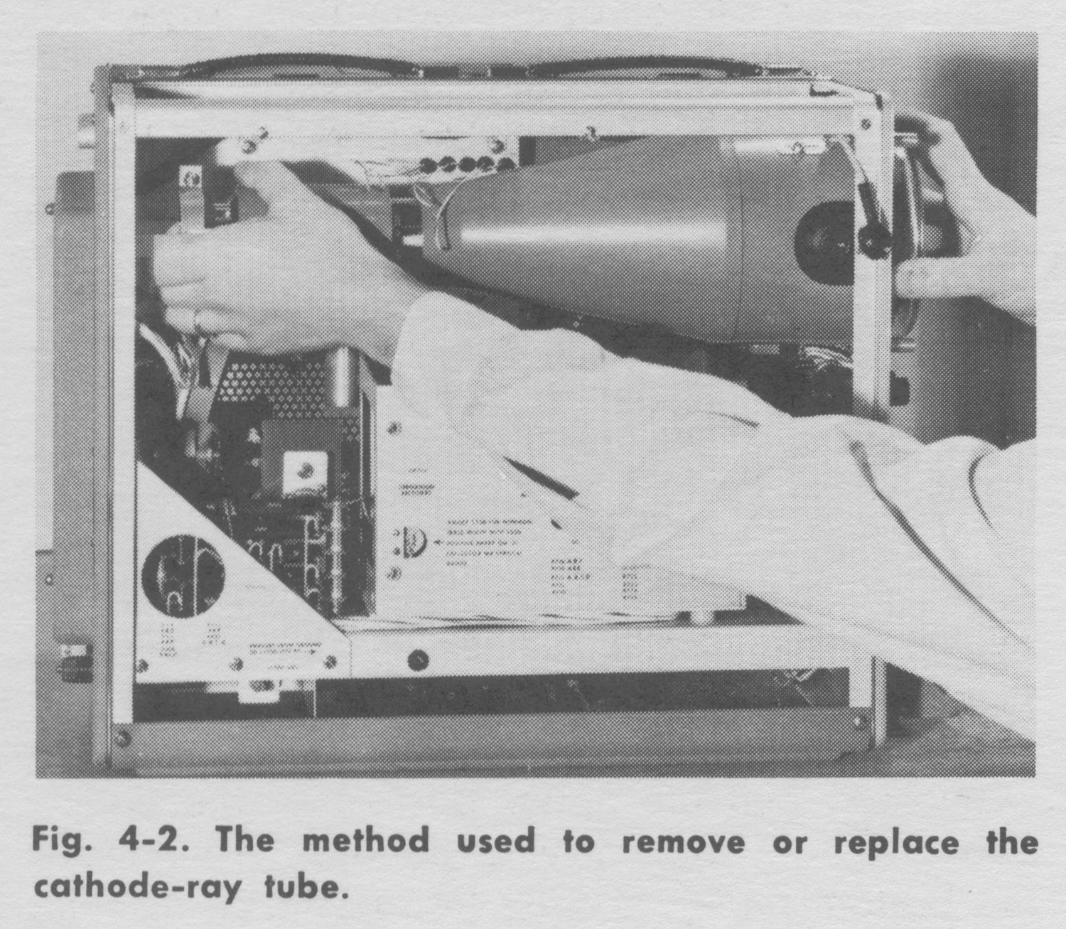
CRT CIRCUIT
Accelerating voltage for the cathode-ray tube is obtained by rectifying a 60-kc ac voltage produced by a vacuum tube oscillator. V610 is the oscillator tube with the primary of T620 serving as a tapped inductor. Rectifiers V630 and V631 supply -1700 volts to the crt cathode and +2300 volts to the post acceleration anode for a total of 4 kv
accelerating voltage.
The high voltage is adjusted by means of R626 in the regulator circuit. The voltage at this point is compared with -150 volts in V605A. The amplified error signal is applied to the grid of the shunt regulator tube, V605B, which varies the screen voltage of the oscillator tube.
The INTENSITY, FOCUS, and ASTIGMATISM controls adjust the crt operating voltages for the desired intensity and focus the beam. The GEOM. ADJ. control adjusts the voltage on the second anode of the crt for best linearity at the extremes of deflection.»
§§§
Per consultare la prima parte scrivere “570” su Cerca.
La prima foto è di Daniele Maiani, le altre di Claudio Profumieri. Elaborazioni, ricerche e testo a cura di Fabio Panfili.
Per ingrandire le immagini cliccare su di esse col tasto destro del mouse e scegliere tra le opzioni.
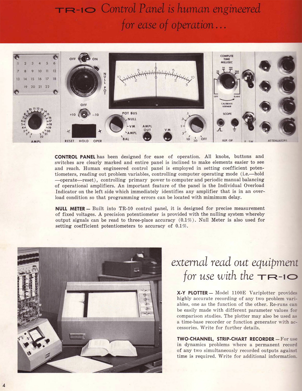
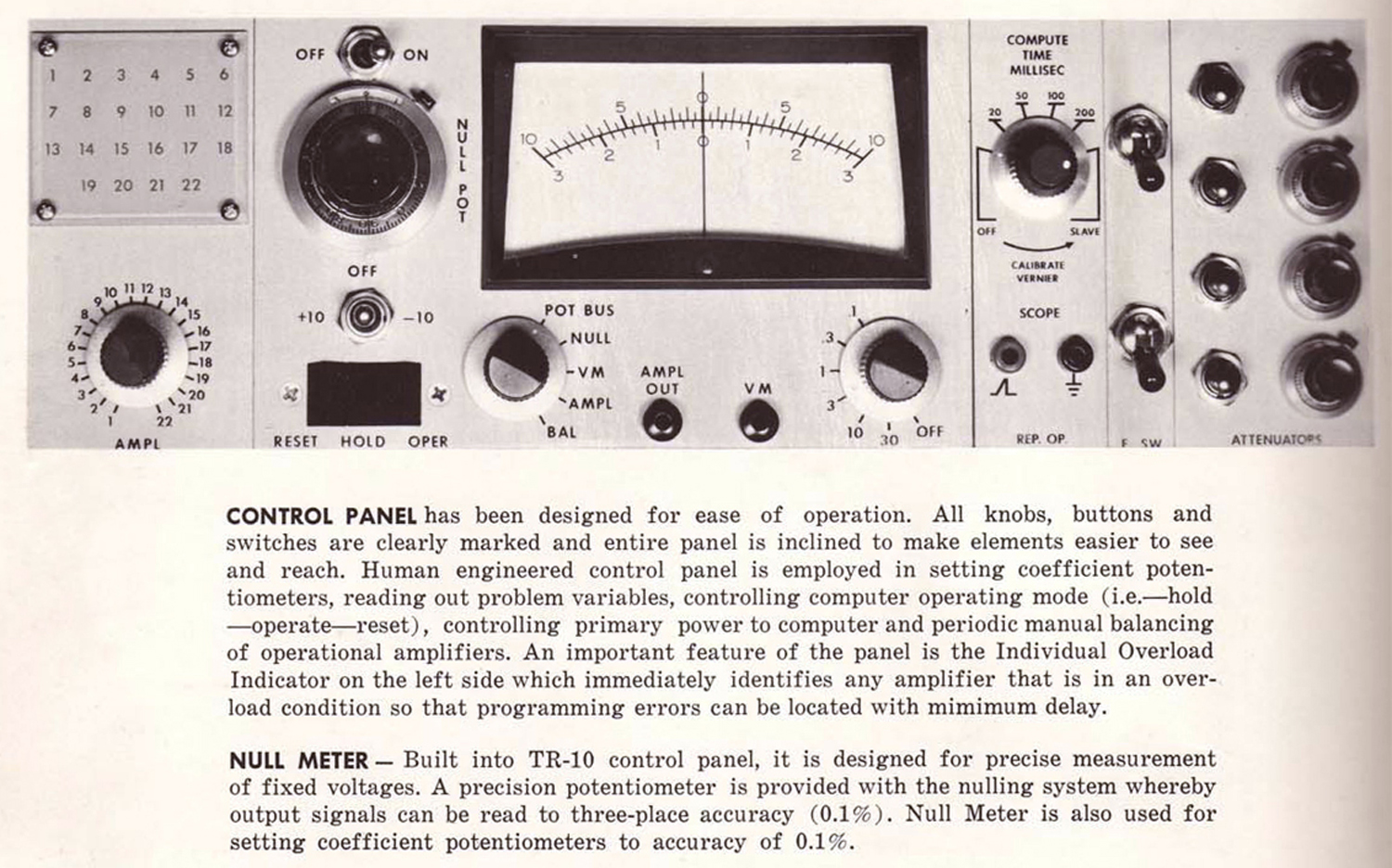
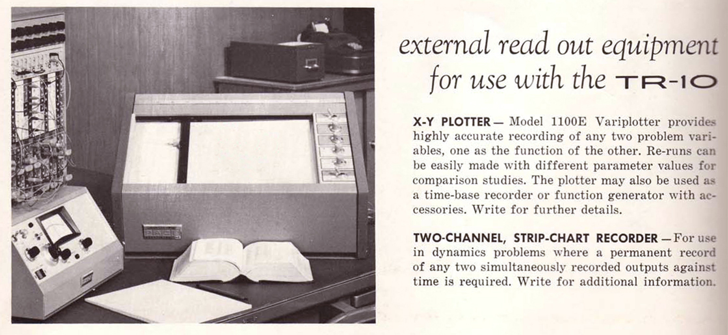
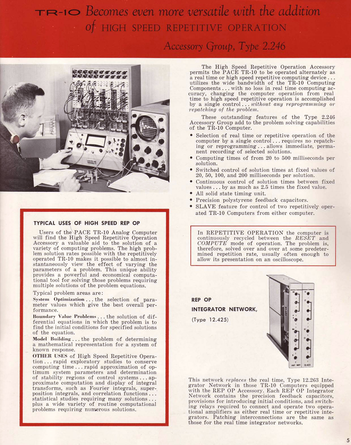
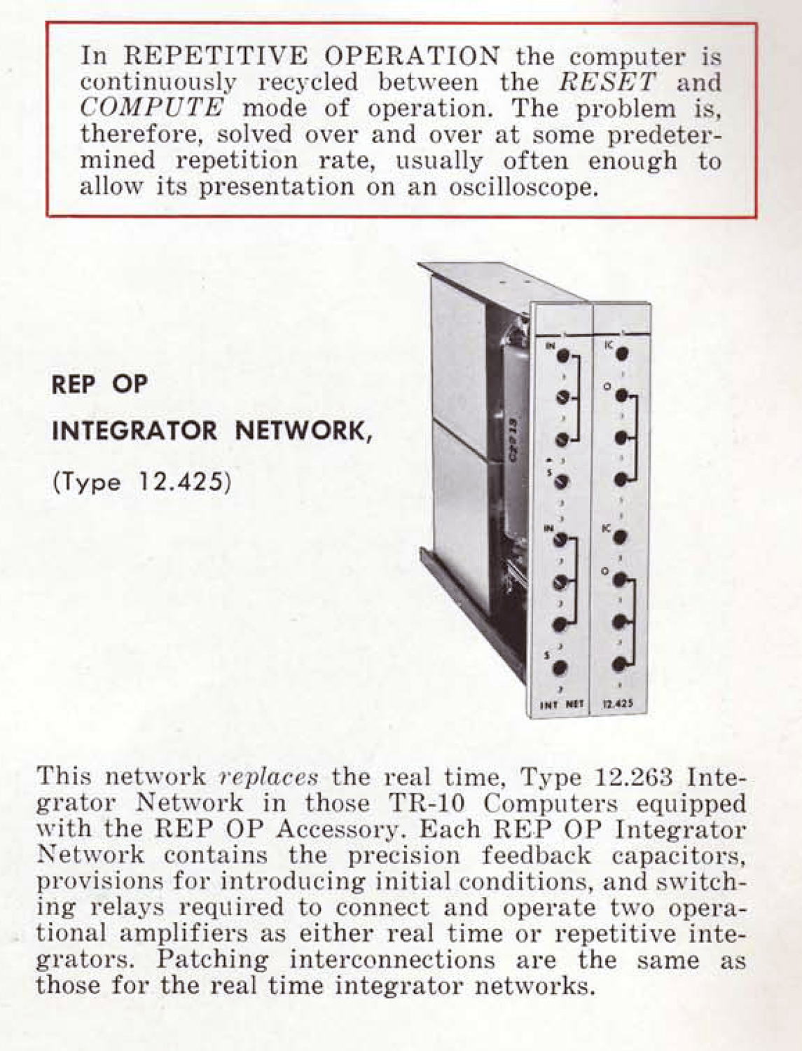
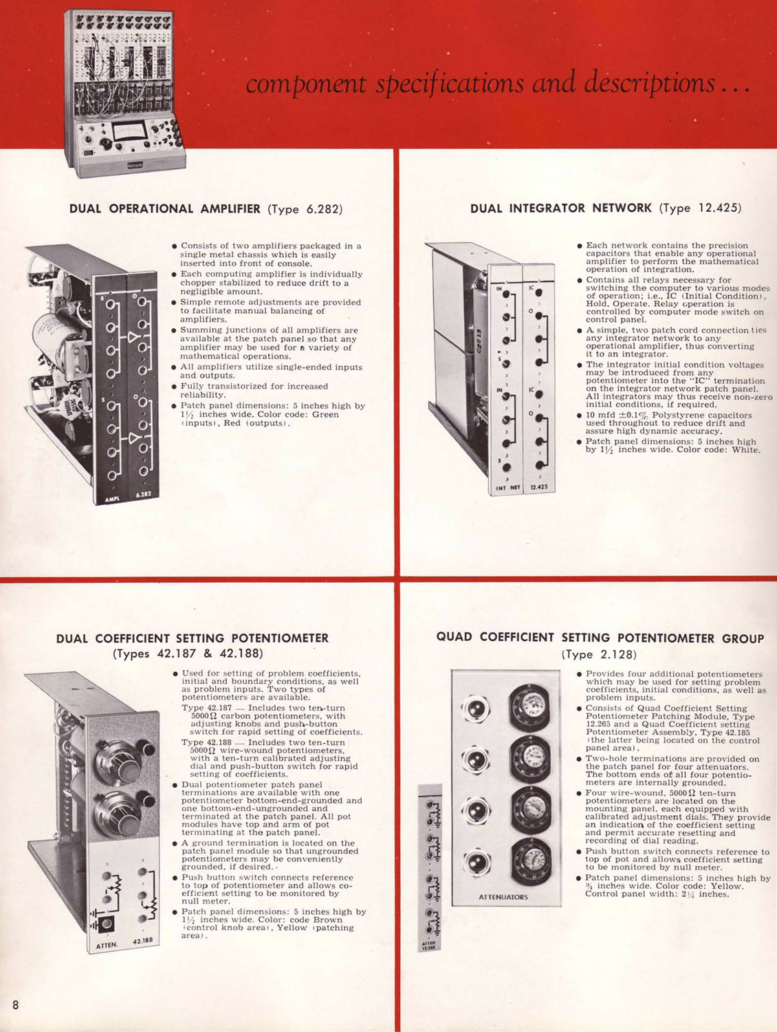
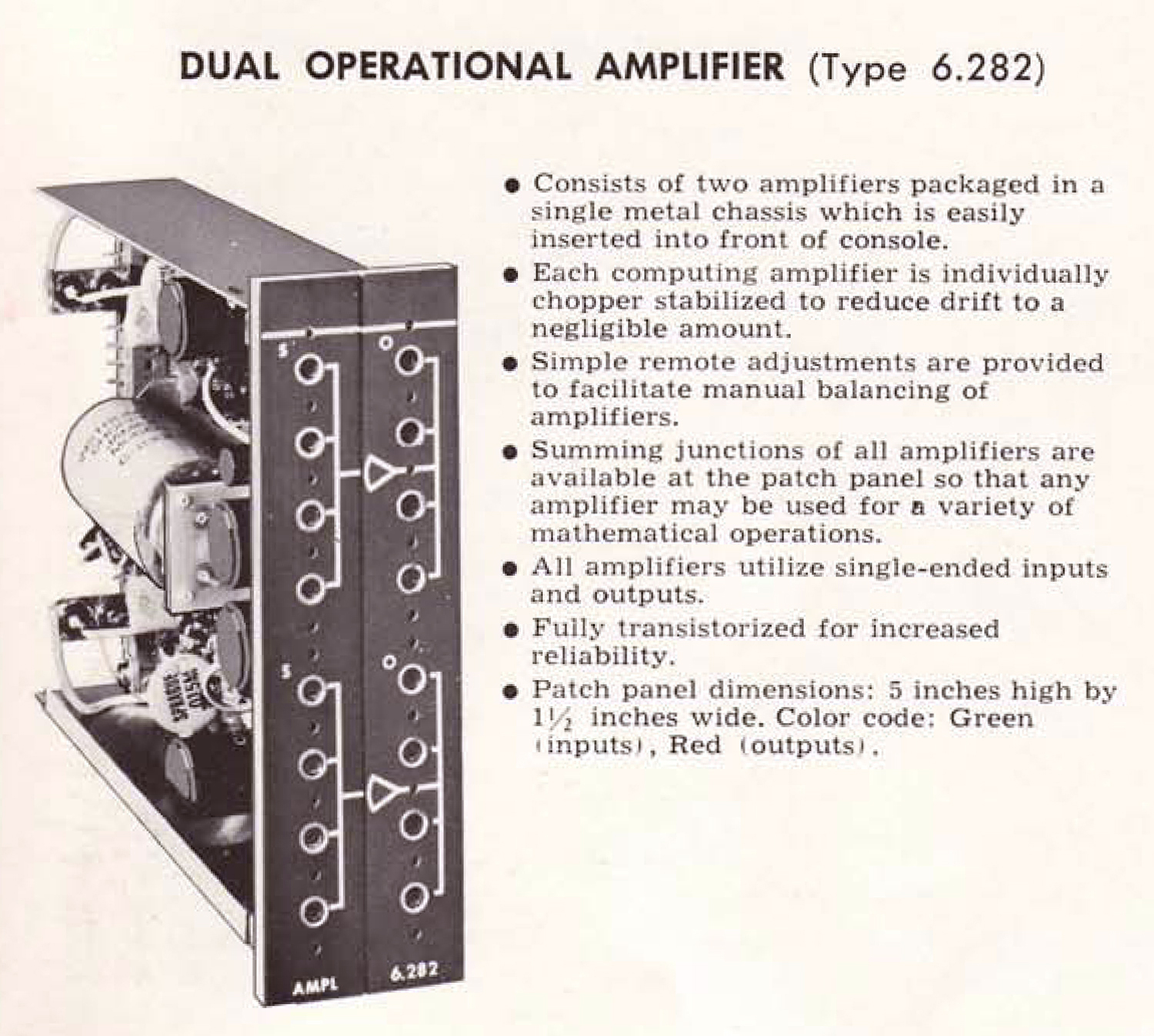
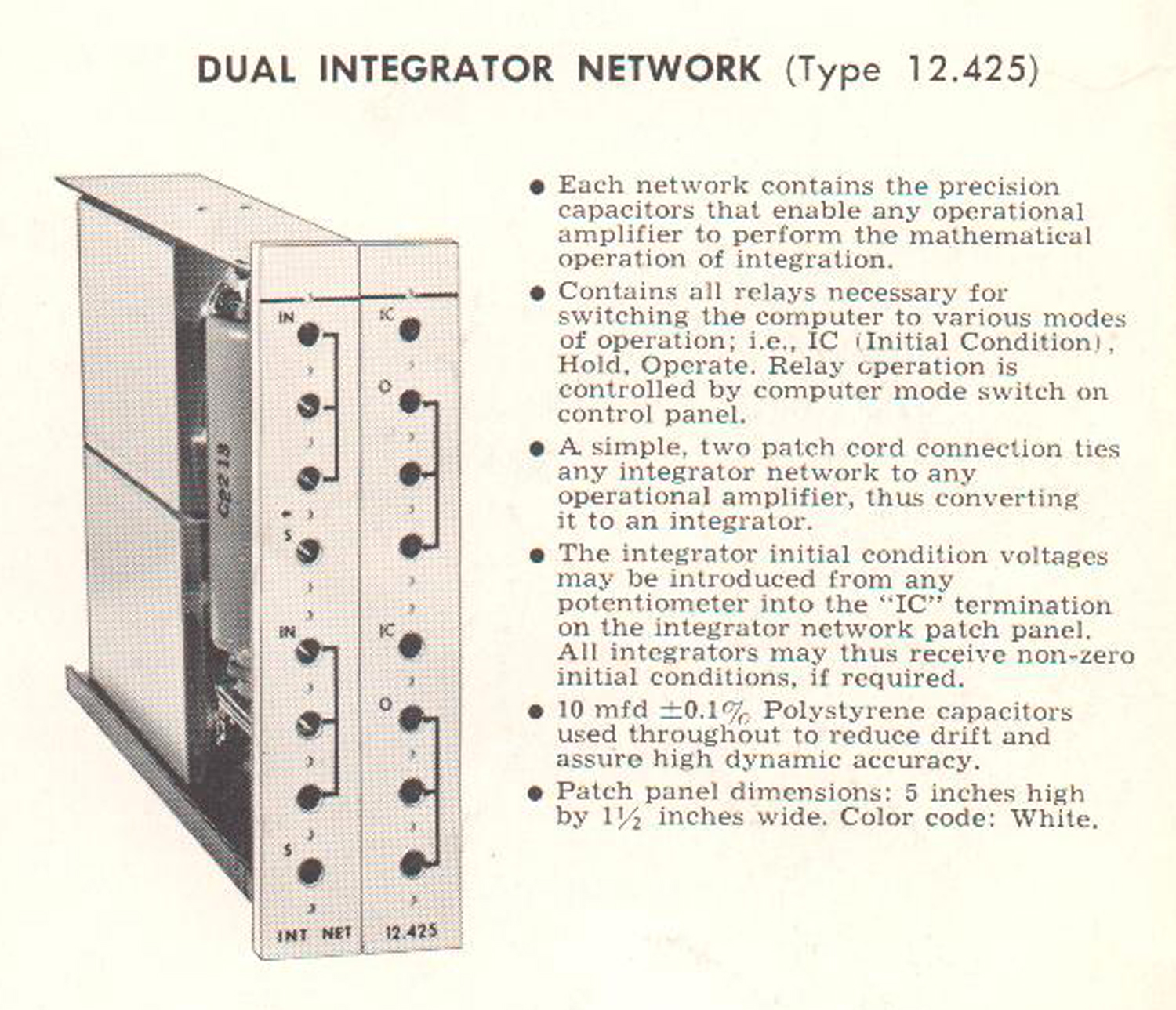
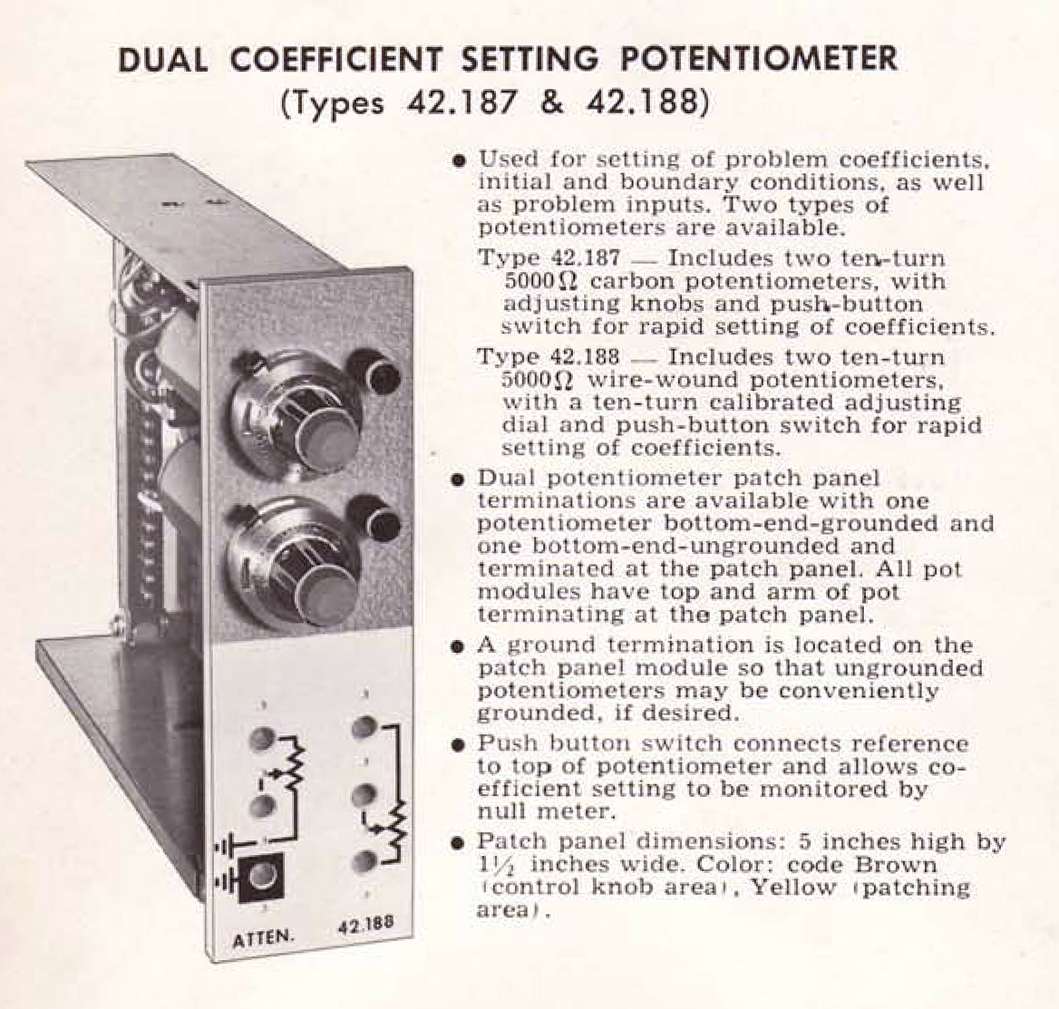
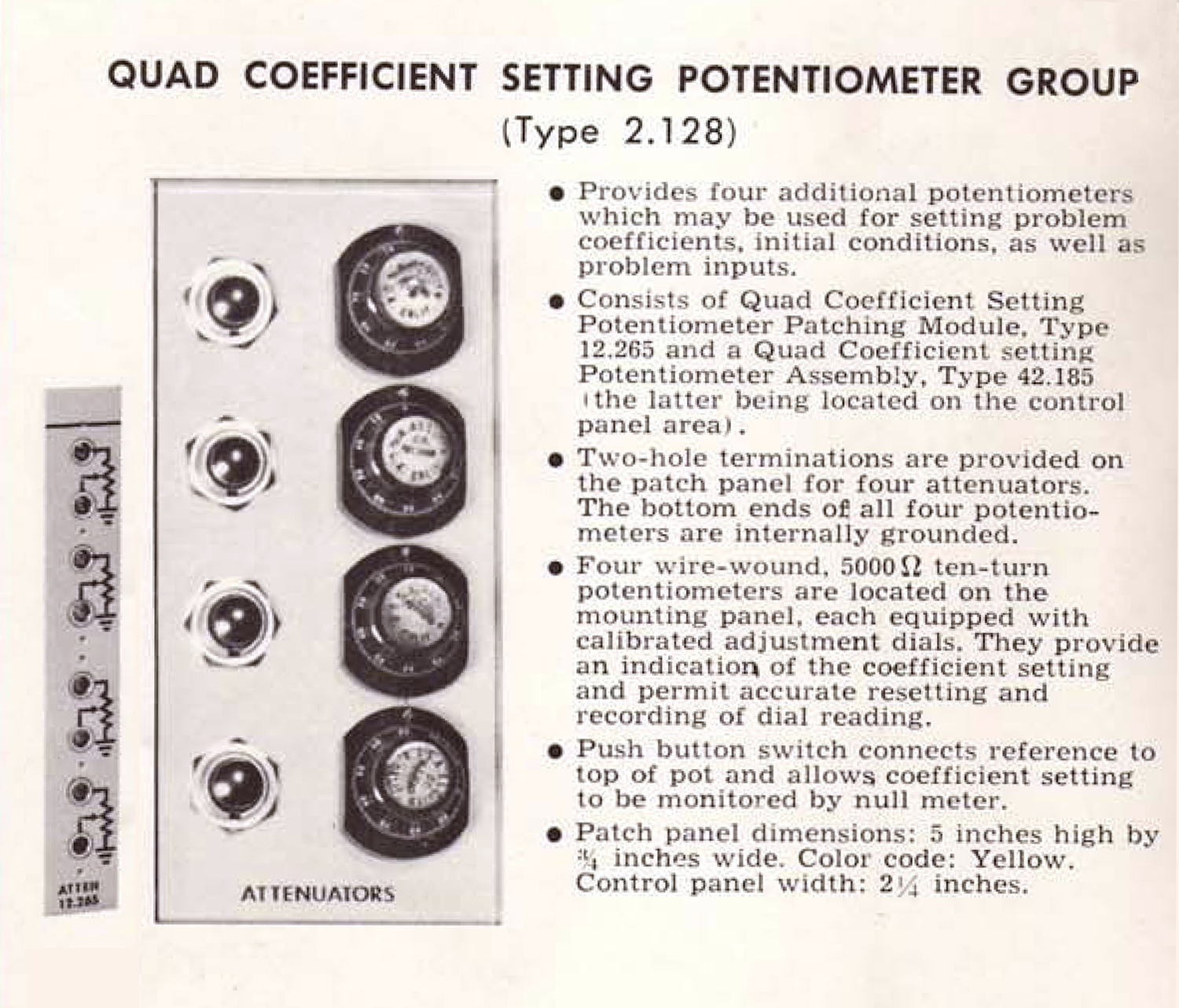
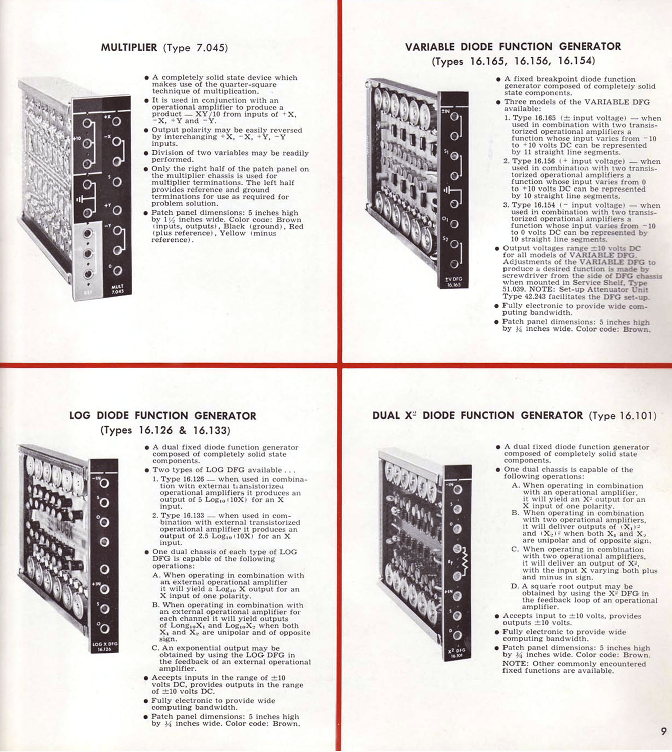
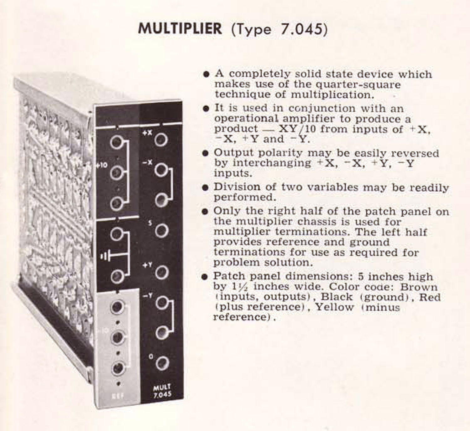
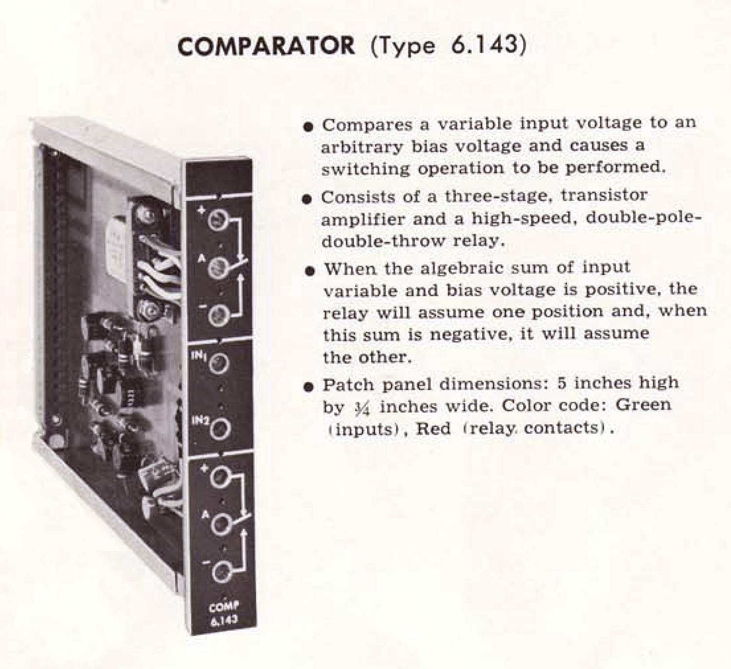
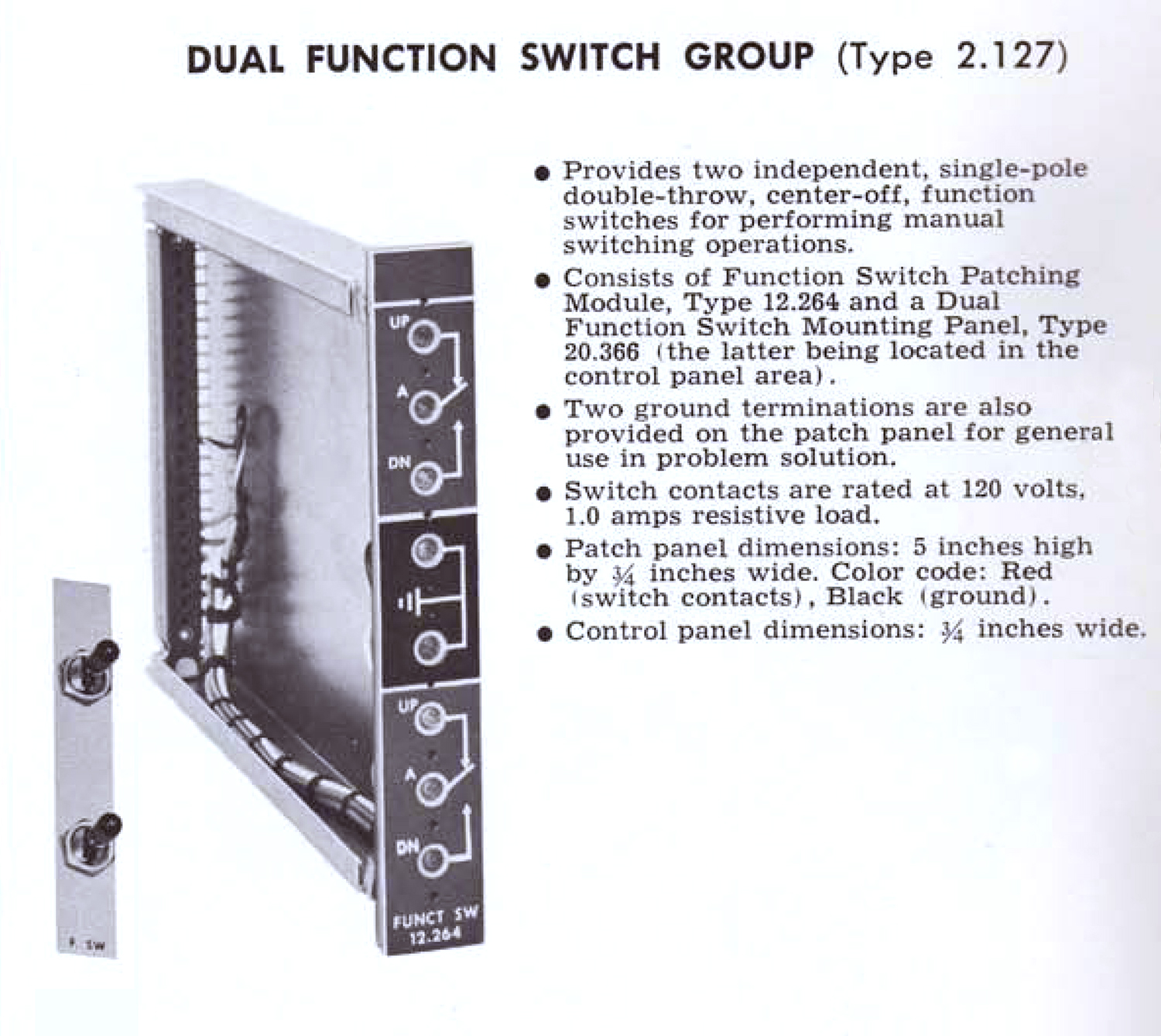
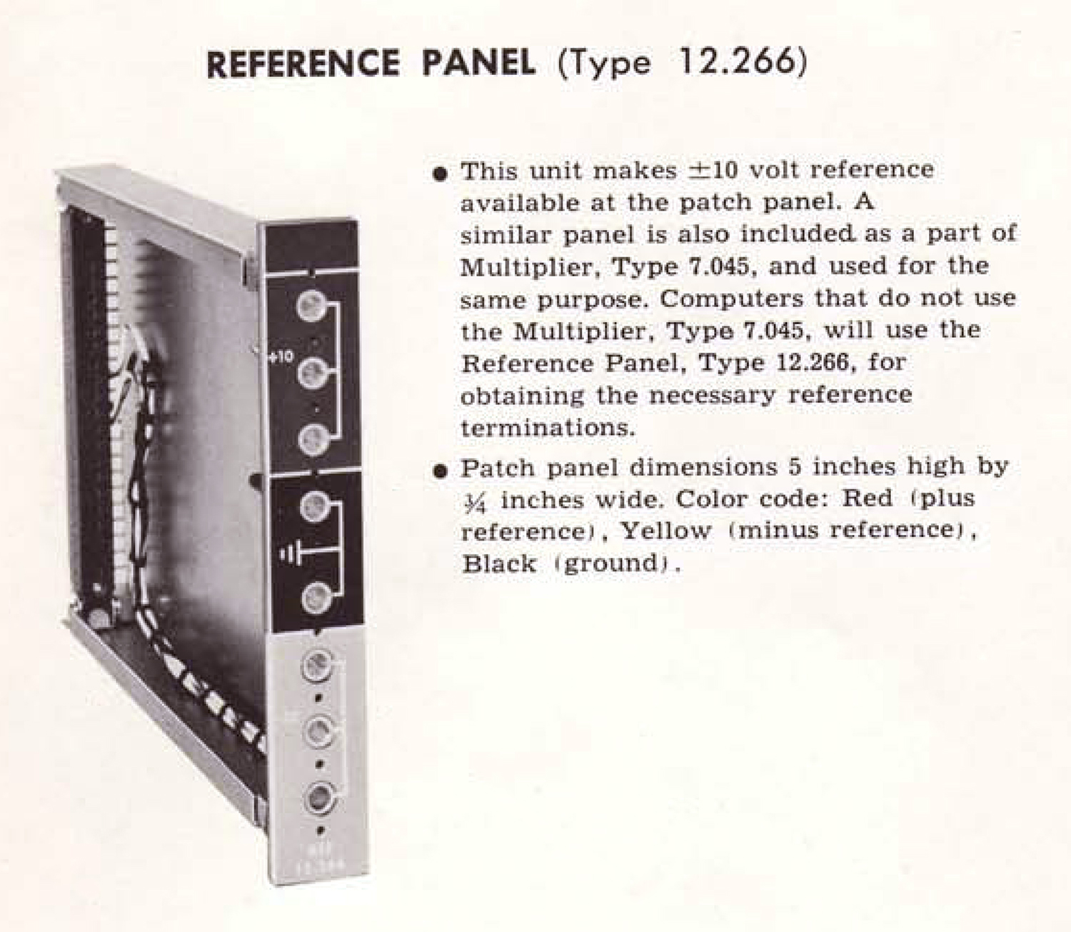
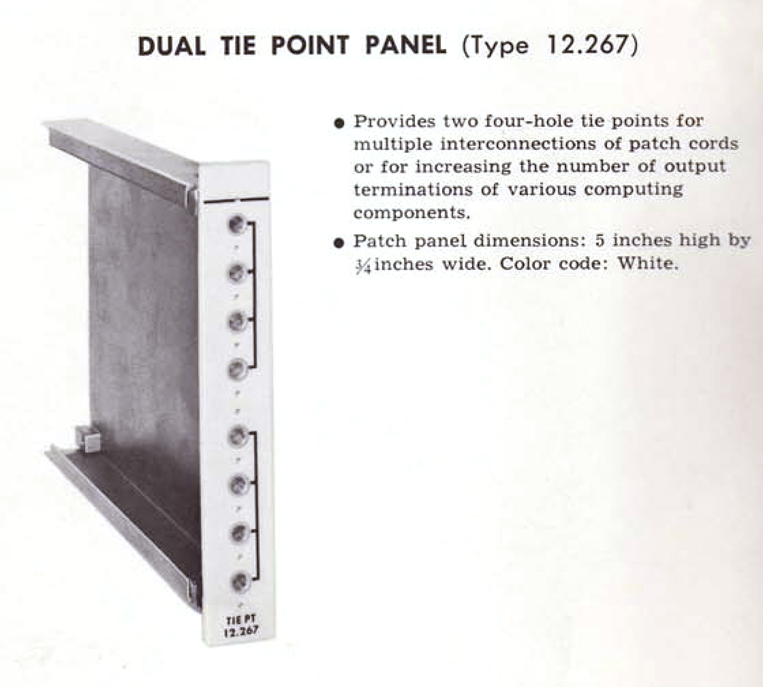
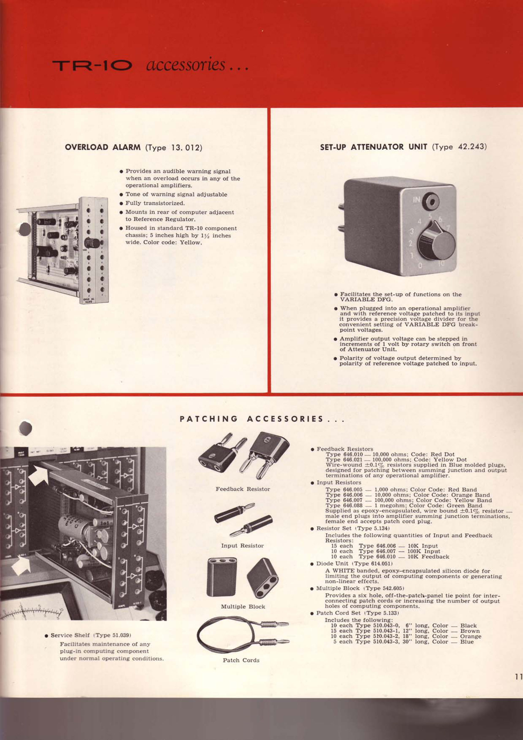
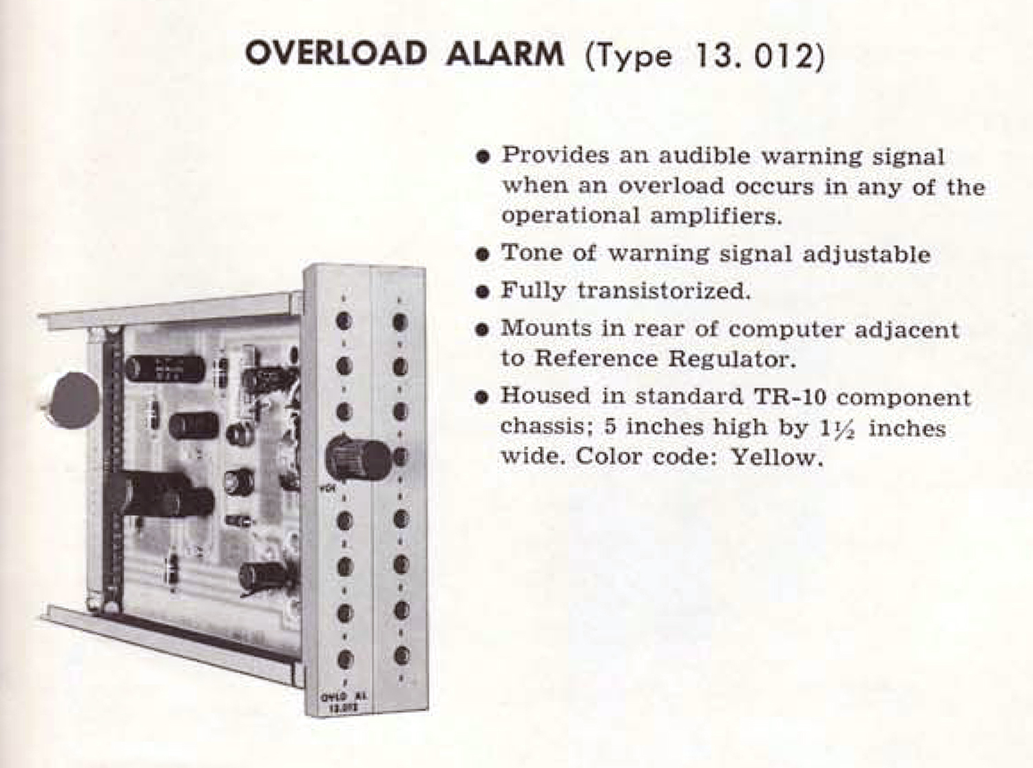
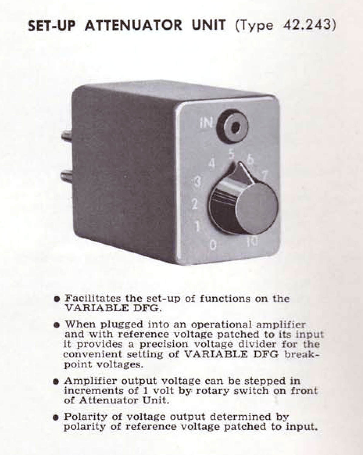
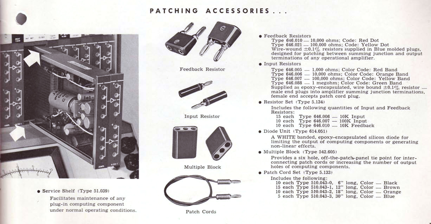
Calcolatore analogico EAI PACE TR-10 3ª parte (Museo MITI)
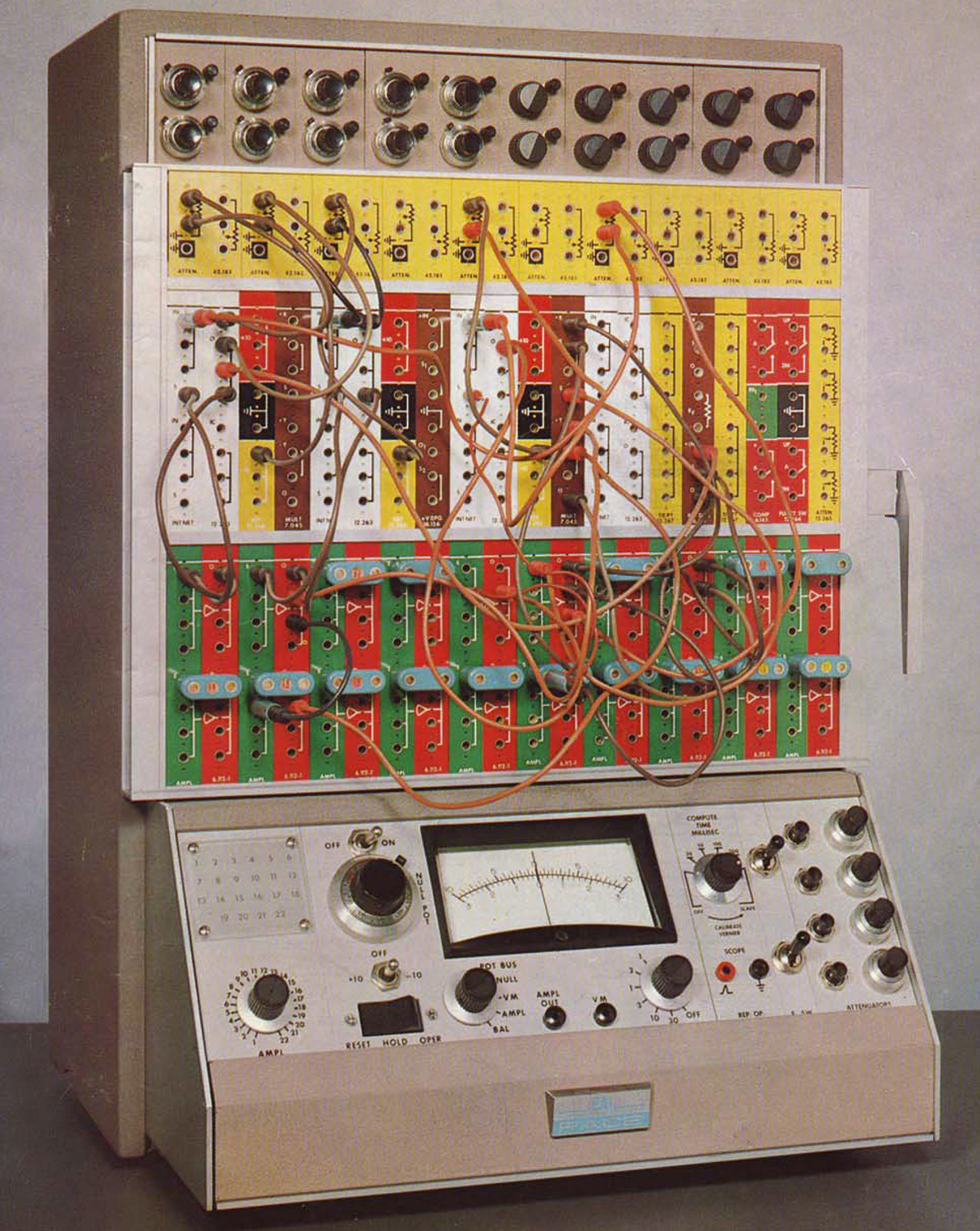 Calcolatore analogico EAI PACE TR-10 (Electronic Associates Inc.). Terza parte.
Nell’inventario D del 1956 si trova al n° 3299, risulta acquistato nel dicembre del 1962, importato dalla Silverstar Ltd.-Milano e destinato al Laboratorio di Elettronica. In una targhetta si legge: “Dono della Fondazione Carlo e Giuseppe Piaggio – Genova”.
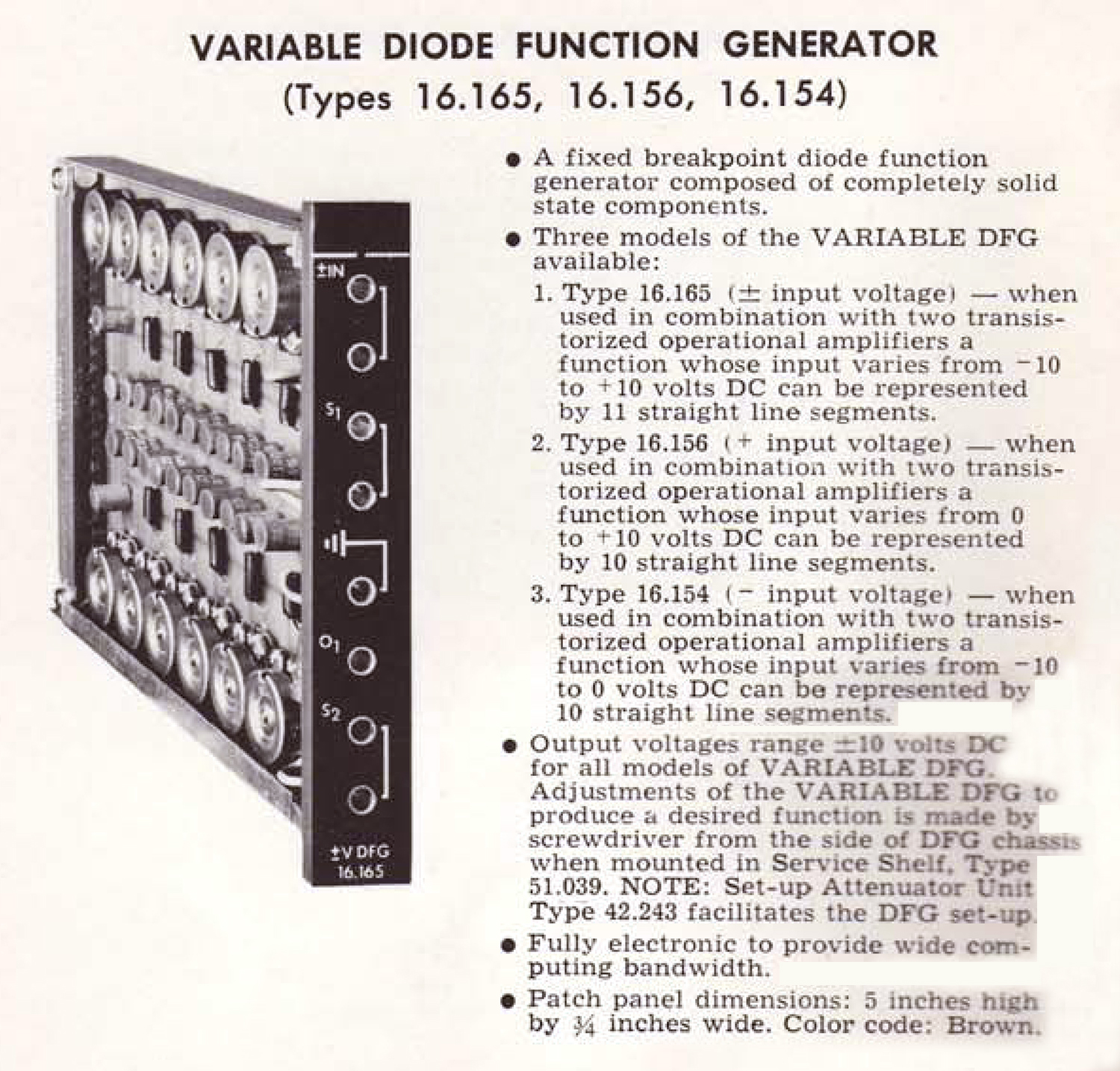
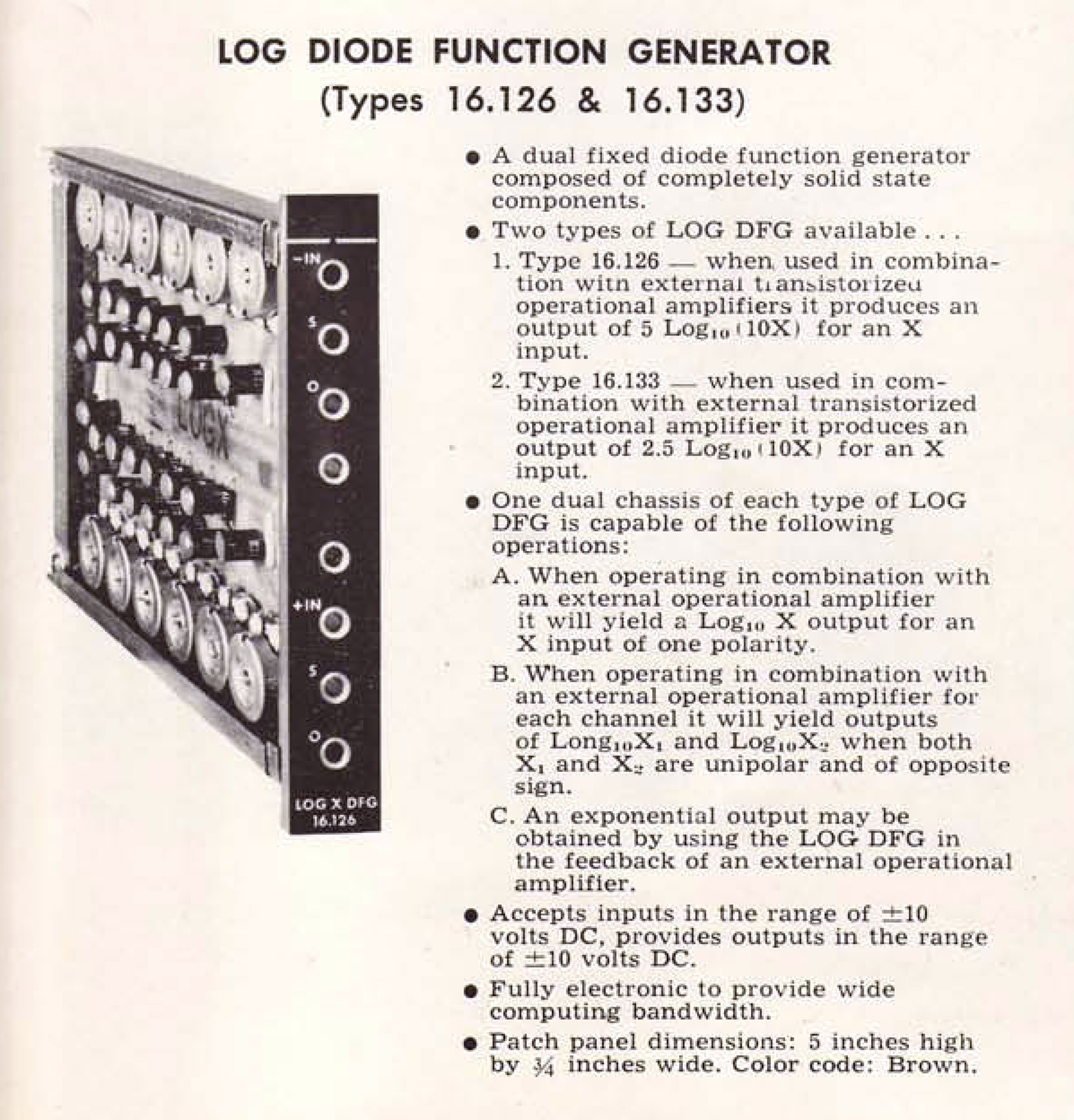
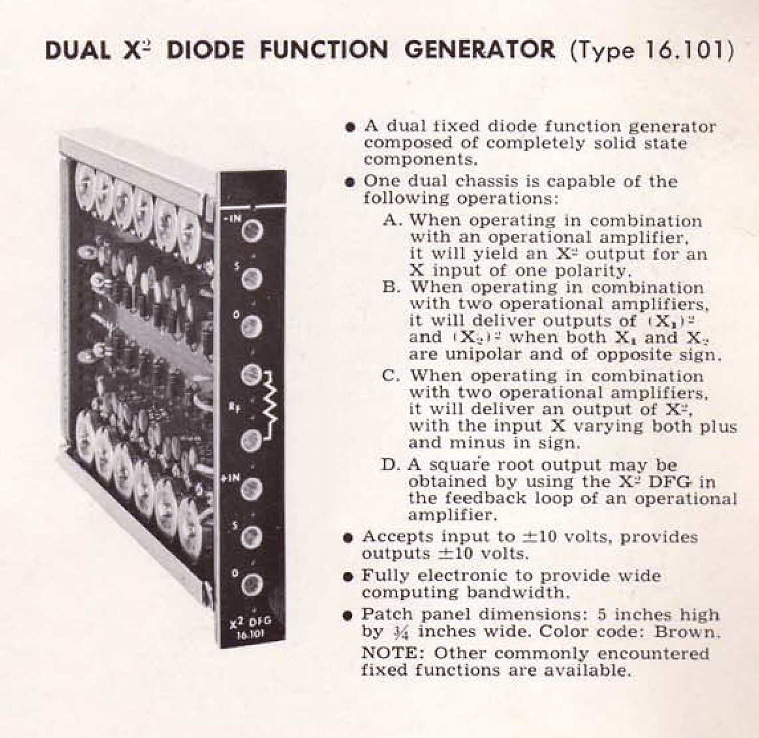
Queste immagini sono tratte da una brochure trovata in rete.
Indirizzi utili:
http://www.analogmuseum.org/library/eai_tr-10.pdf
http://bitsavers.org/pdf/eai/tr-10/AC6020-1_EAI_PACE_TR-10_Analog_Computer_Operators_Handbook.pdf
http://bitsavers.org/pdf/eai/tr-10/EAI_TR-10_Brochure.pdf
http://bitsavers.org/pdf/eai/tr-10/TR10-Application%20Notes.pdf
Per consultare le altre schede dedicate ad esso scrivere “TR.10” su Cerca.
Il calcolatore è esposto al Museo MITI, su proposta di Fabio Panfili.
Elaborazioni, ricerche e testo di Fabio Panfili.
Per ingrandire le immagini cliccare su di esse col tasto destro del mouse e scegliere tra le opzioni.