3300A FUNCION GENERATOR della HEWLETT PACKARD GMBH. Matr. N° G 746-00720. Terza parte.
È facile trovare le istruzioni in internet agli indirizzi elencati sotto.
http://bee.mif.pg.gda.pl/ciasteczkowypotwor/HP/3300A.pdf
http://hpmemoryproject.org/wb_pages/wall_b_page_10c.htm
http://www.kennethkuhn.com/students/ee431/mfg_data/hpj_nov_1965.pdf
http://www.hpl.hp.com/hpjournal/pdfs/IssuePDFs/1968-05.pdf
Da questi si deduce che il generatore di funzioni 3300A è stato messo sul mercato nel 1965; mentre il plug-in 3305A è in vendita dal 1968.
Quel che segue è tratto dalle istruzioni della H-P conservate nell’archivio della Sezione Elettronica.
§§§
«SECTION IV
THEORY OF OPERATION
4-1. INTRODUCTION.
4-2. This section contains a description of the theory of operation of the -hp- Model 3300A Function Generator with the -hp- Model 3301A Auxiliary Plug-in.
4-3. GENERAL DESCRIPTION.
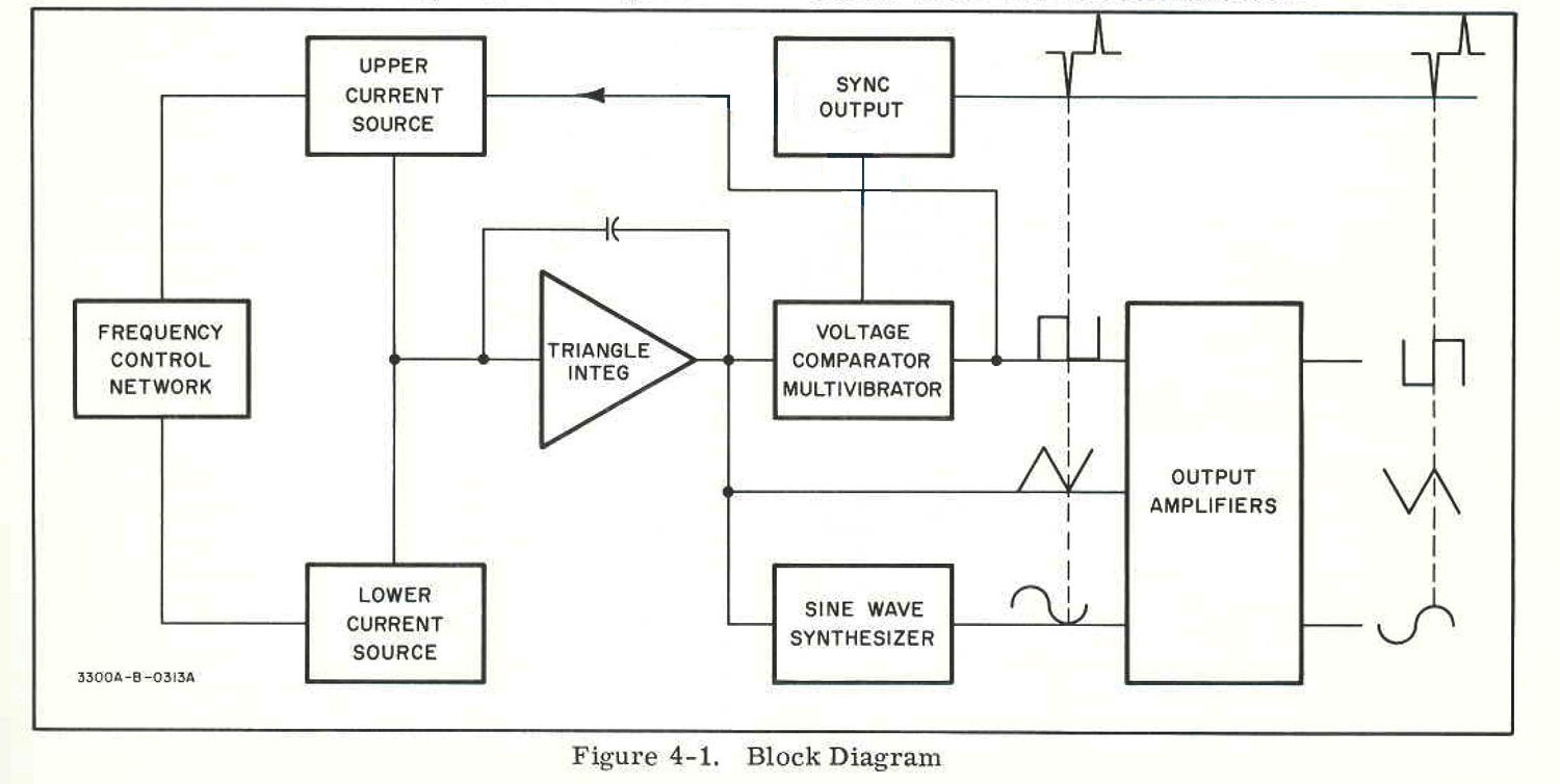 4-4. The Model 3300A comprises a frequency control network, two current sources, a triangle integrator, a voltage comparator multivibrator, a sine wave synthesizer and output amplifiers. (Refer to Figure 4-1).
4-5. The Model 3301A Auxiliary Plug-in comprises shorting wires to provide internal connections for Model 3300A operation.
4-6. The voltage comparator multivibrator, current sources and triangle integrator form the basic function generating loop. The voltage comparator multivibrator changes state at predetermined limits onthe positive and negative slopes of the output of the triangular integrator. The effect of the change of state in the upper current source, reverses the input to the triangle integrator. A cycle is as follows: when the amplitude of the positive slope of the triangle wave reaches the upper predetermined limit of the voltage comparator multivibrator, the multivibrator changes state. This change of state reverses the current into the triangle integrator through control of the upper current source which causes the output of the integrator to decrease. The decrease continues until the amplitude of the negative slope reaches the lower predetermined limit. At this point, the voltage comparator multivibrator changes state and again reverses the direction of current at the input of the integrator and causes the output of the integrator to rise. This rise continues until the voltage comparator multivibrator again changes state thus completing the cycle.
4-7. The frequency control network, governed internally by the FREQUENCY Dial or externally through the FREQUENCY CONTROL, determines the amount of current in the current sources, which varies the frequency as follows: an increase or decrease in input current increases or decreases the slope of the triangle wave, respectively. (A change in direction of input current reverses the slope.) Frequency will increase if the + and – slopes are increased, as less time is required for the + or – slope of the triangle wave to reach the predetermined limits in the voltage comparator multivibrator.
4-8. The sine wave is synthesized from the triangle wave by a nonlinear network. This network consists of resistors and diodes biased so different diodes conduct during different voltage levels of the triangle wave. These diodes, when conducting, provide additional shunt paths within the network. Each additional shunt path changes the slope of the triangle wave so that the wave is shaped to approximate a sine wave.
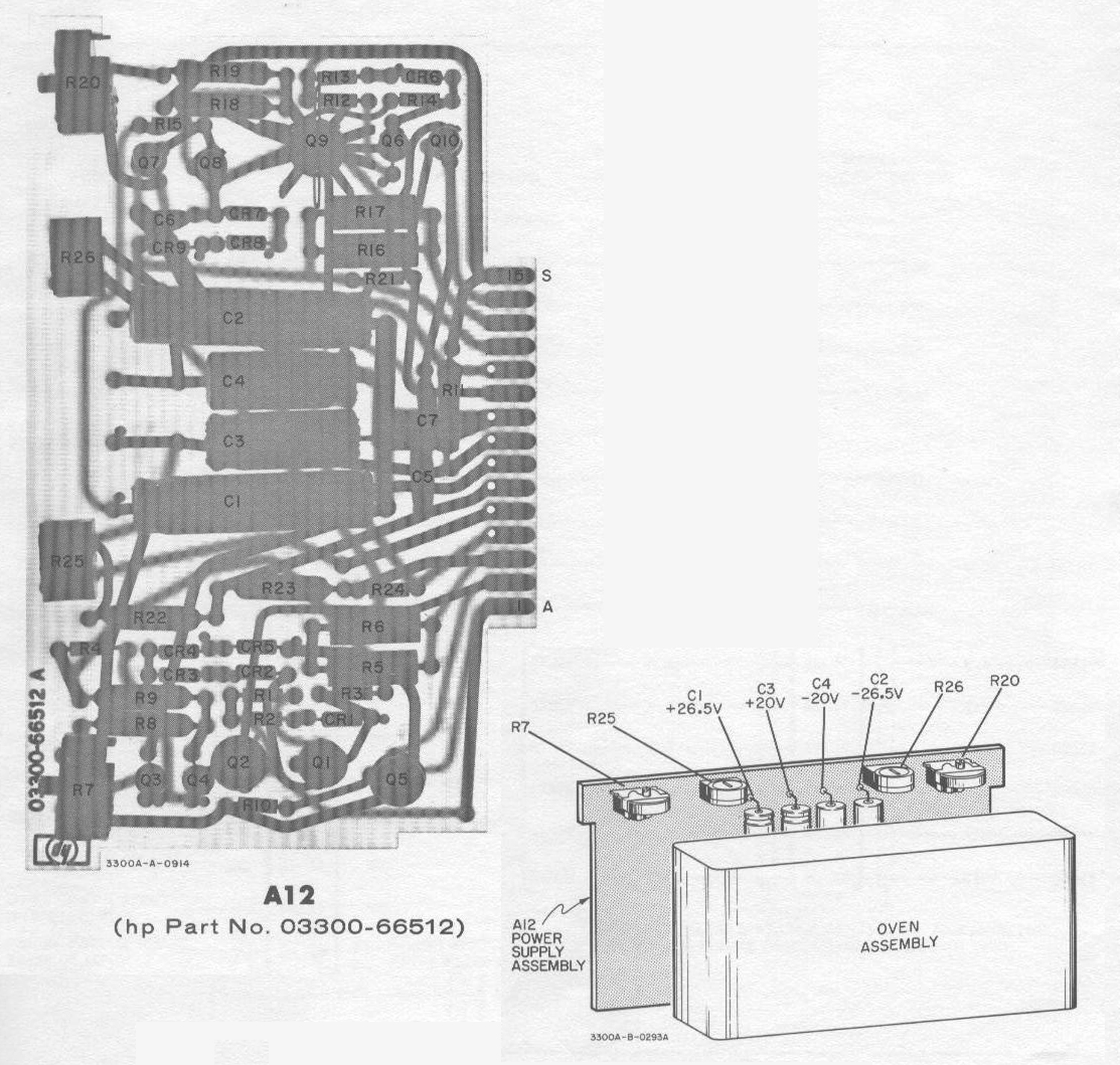
4-9. The output amplifiers are dc coupled and fully floating with respect to power line ground. CHANNEL A and CHANNEL B amplifiers are identical and use a differential amplifier at the input. To maintain the same peak-to-peak amplitude regardless of function selected, the overall closed loop gain of the amplifier is varied with function selection. The sync pulse is produced by an RC differentiating network. The negative Pulse at the output is in phase with the positive crest of the sine and triangle wave.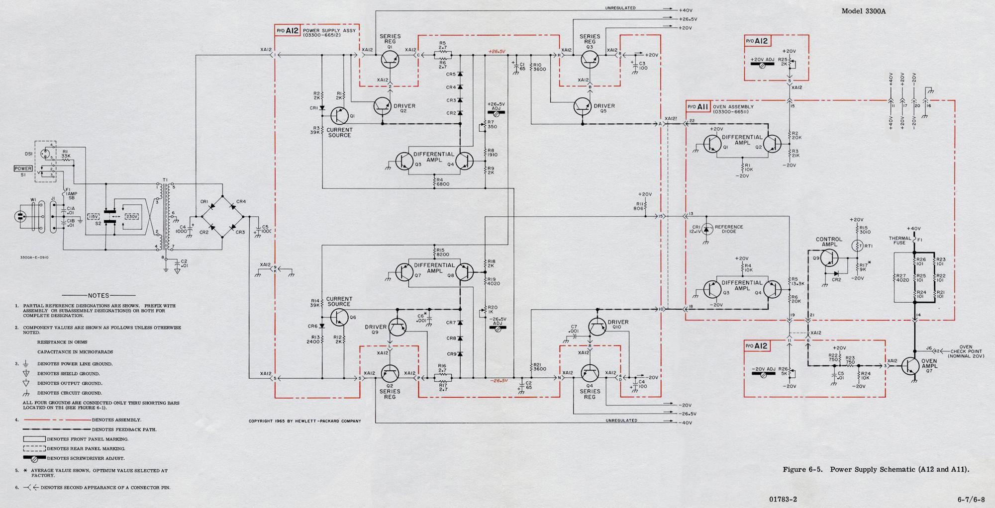 4-11. Power Supply (Refer to Figure 6-5) can operate on either 115 or 230 volts input and delivers 3 pairs of voltages, ± 40 V, 126. 5 V, and 120 V. The 40 volt supply provides power for the oven heater. The 26.5 volt supplies are regulated and the 20 volt supplies are double regulated.
4-12. Critical temperature sensitive components are housed within an oven in which the temperature is maintained at approximately 80°C (176 °F).
4-13. SCHEMATIC THEORY.
4-14 FREQUENCY CONTROL NETWORK.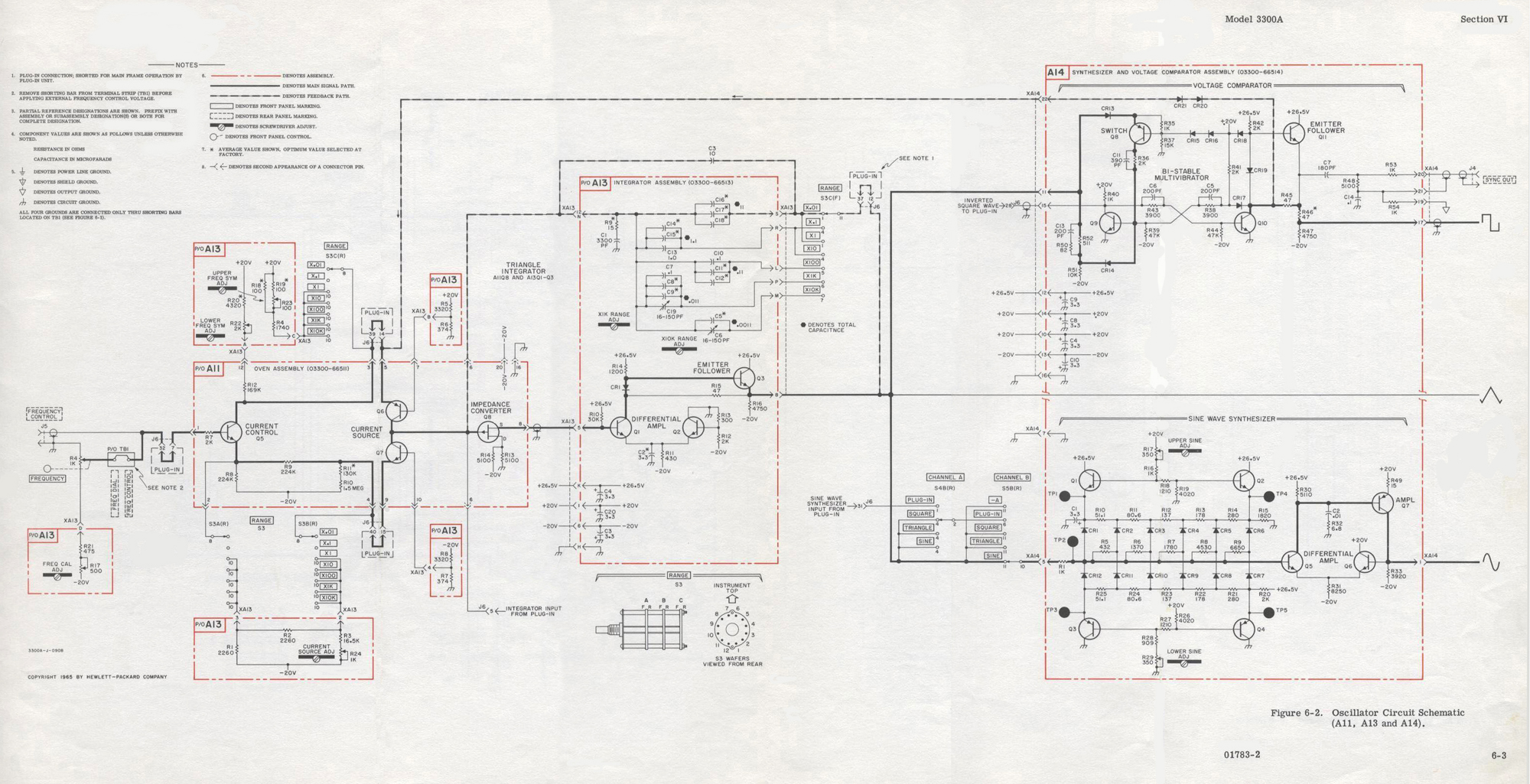 4-15. (Refer to Figure 6-2) The FREQUENCY dial (R4) in conjunction with the RANGE switch (S3) provides internal frequency control. The basic frequency equation can be expressed as
f = i/(2C Δ eout)
Where i is the current to the triangle integrator, C is the triangle integrator feedback capacitor and eout is the peak-to-peak voltage of the triangle wave. The position of the RANGE switch determines the integrating capacitor C. The FREQUENCY dial or external control voltage determines the current i. The frequency control voltage is applied to the current control transistor A11Q5, which establishes the amount of current available to the triangle integrator from the current sources A11Q6 and A11Q7.
4-16. CURRENT SOURCES.
The state of current source A11Q6 is controlled by the voltage comparator multivibrator, and in turn, controls the direction of the current in the input of the triangle integrator. When A11Q6 is on, a current, a i, flows through it and divides i into the integrator and i through current source A11Q7. When the bi-stable multivibrator changes state and gates A11Q6 off, 2 i no longer flows; however, the current through A11Q7 remains the same. Therefore, a current equal to i but opposite in direction flows from the triangle integrator input.
4-17. TRIANGLE INTEGRATOR.
The triangle integrator consists of an impedance converter A11Q8 (a field effect transistor), a differential amplifier A13Q1 and A13Q2, an emitter follower A13Q3, diode A13CR1, and the capacitive feedback
network: this circuit integrates the constant current inputs into the positive and negative slopes which make up the triangle wave. The triangle wave is applied to the inputs of the output amplifiers, sine wave synthesizer and voltage comparator multivibrator.
4-18. VOLTAGE COMPARATOR MULTIVIBRATOR.
The voltage comparator multivibrator consists of a voltage comparator switching network, A14Q8, A14CR13 and AMCR14; a bi-stable multivibrator A14Q9 and Q10 and an emitter follower A14Q11. A14CR19 and R45 provide a low resistive path to ensure rapid rise and fall time of the square wave in the event the capacitance of the load is high. When the positive slope of the triangle wave reaches +20 volts, A14CR13 is turned on. A14Q9 is then turned on which turns A14Q1O off. The rise in the collector voltage of A14Q10 is coupled through emitter follower A14Q11 and through A14CR20 and A14CR21 into the emitter circuit of A11Q6, and turns it on. The output slope then becomes negative. A11Q6 remains on until the negative slope reaches zero volts. At the zero point on the negative slope A14CR14 is turned on which causes the bi-stable multivibrator to change state so
that A14Q9 is now off and A14Q10 is on. The decrease in A14Q10 collector voltage gates the current source, A11Q6, off which reverses the integrator input current. The positive slope then begins increasing toward the upper limit, +20 volts. The output of the emitter follower is differentiated by A14C7 and A14R48 to provide the sync output. A negative sync pulse occurs at the crest of sine and triangular wave. See Figure 4-1.
4-19. SINE WAVE SYNTHESIZER.
(See Figure 6-2) The sine wave synthesizer comprises four control transistors, the biased diodes with
associated voltage dividers, a differential amplifier A14Q5, A14Q6 and the output amplifier A14Q7. A14R17 and A14R29 adjust the operating points of the voltage dividers to minimize distortion. The diodes are biased by the four control transistors A14Q1 through A14Q4 and the voltage dividers to provide twelve different current paths in the input to the differential amplifier as the triangle wave progresses. Each slope of the triangle wave is modified in twelve steps so that the waveform appearing at the base of A14Q5 approximates a sine wave. The sine wave synthesizing network is isolated by the differential amplifier A14Q5 and A14Q6 and amplifier A14Q7.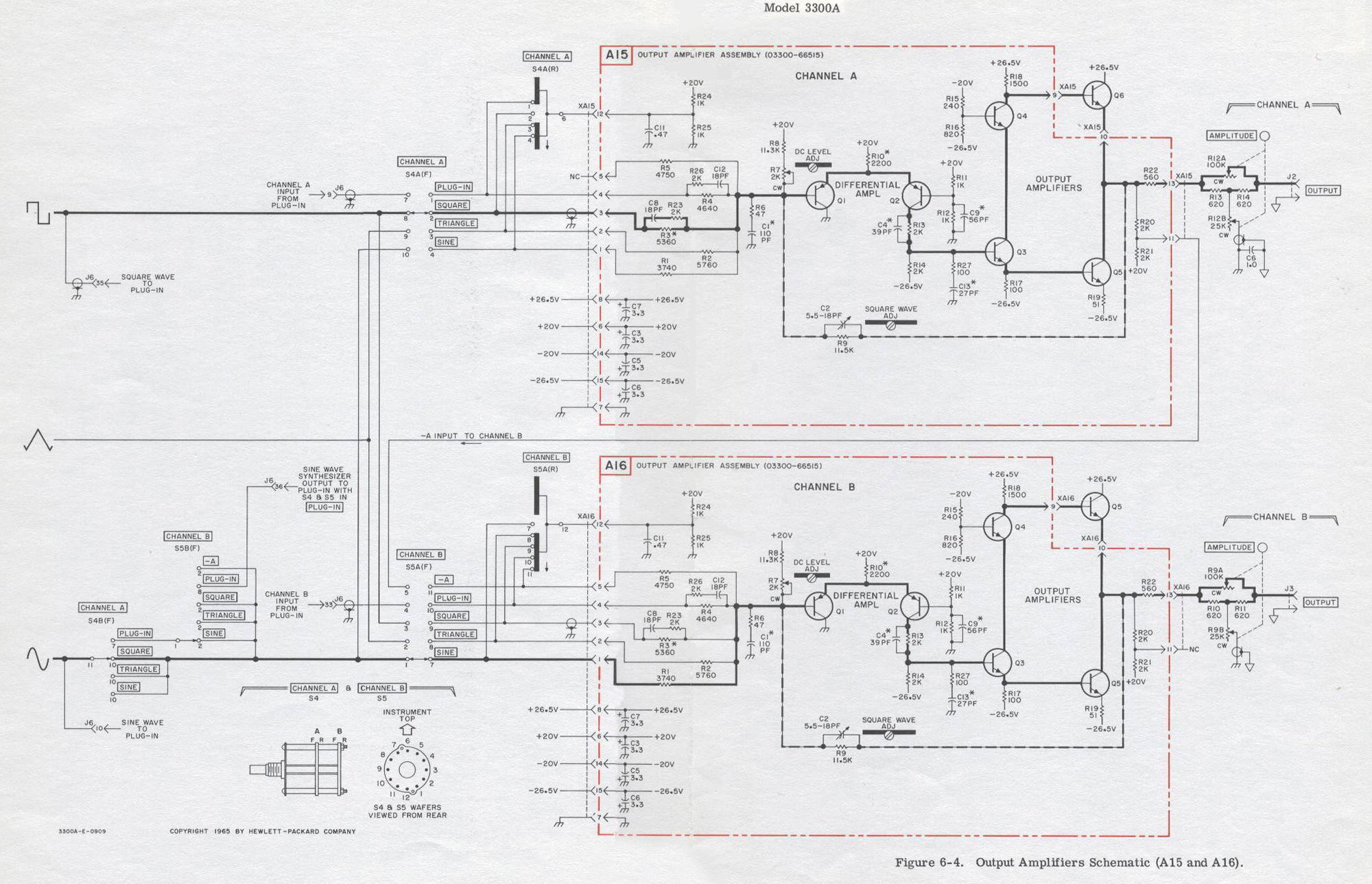 4-20. OUTPUT AMPLIFIERS. (Figure 6-4).
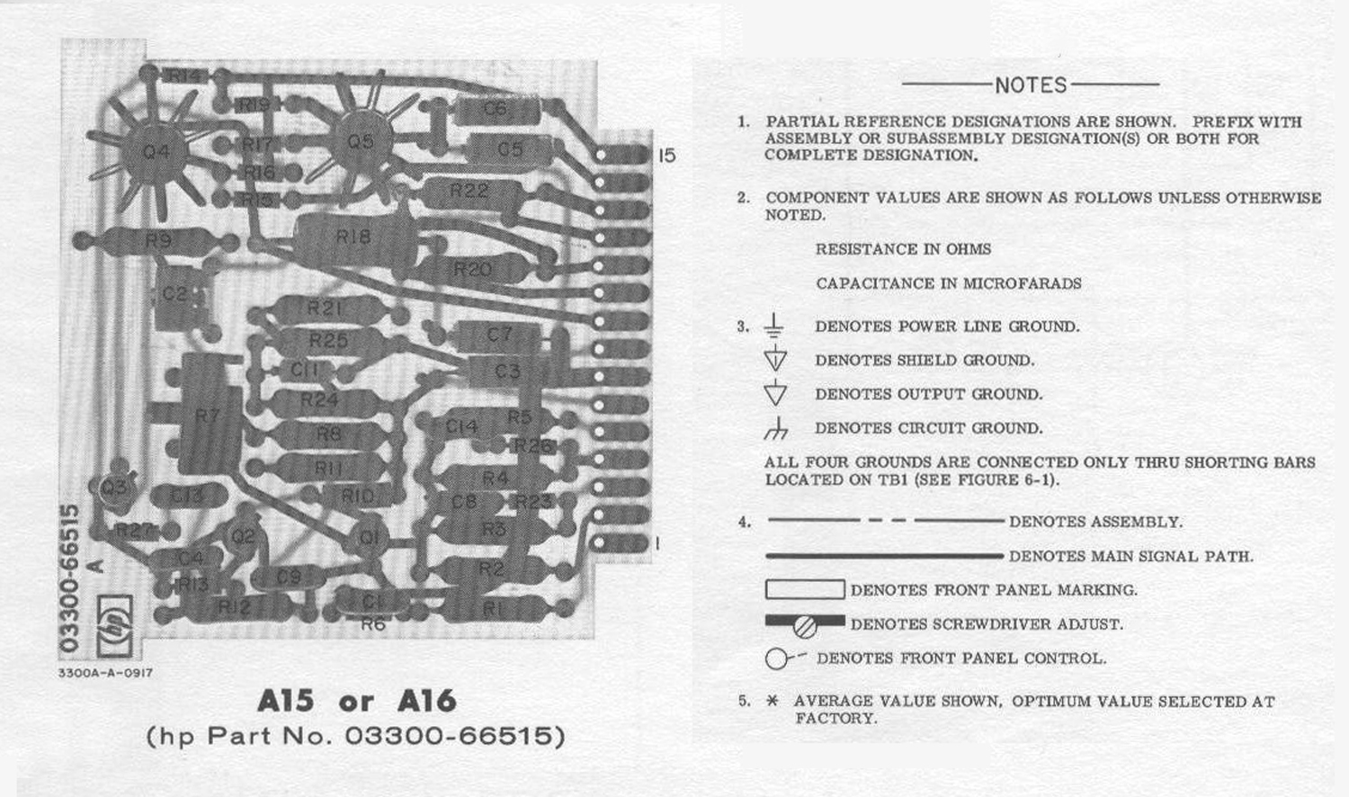
The etched circuit assemblies A15 and A16 are identical. CHANNEL A and CHANNEL B differ due to the -A output of CHANNEL B. The input for CHANNEL B with its function switch in -A position, A16 Pin 5, is taken from the junction of A15R20 and R21, XAI5 Pin 10. The output amplifiers are variable gain amplifiers. Gain is varied by changing the amount of feedback for the different functions. The following reference designators should be prefixed by applicable assembly number. The feedback is varied by resistors R1 through R5 and R23 C8 combination, to maintain equal peak-to-peak amplitude of the various functions for a given AMPLITUDE control setting. A differential amplifier, Q1 and Q2, make up the first stage followed by two additional amplifiers Q3 and Q4. The trimmer C2 in the feedback network is used to shape the square wave. The AMPLITUDE control provides a nominal 600 ohms output impedance, independent of amplitude control setting.
4-21. POWER SUPPLY. (Figure 6-5).
The power supply comprises two full wave rectifiers CR1 thru CR4 and four series regulated supplies. A11CR1 provides the reference point for the two negative regulated supplies which in turn are the references for the two positive regulated supplies. The two 20 volt supplies are double regulated. The operation of the four supplies is similar. A differential amplifier senses and amplifies any change. The change is applied through a driver stage to the series regulator which then changes its conduction to oppose the change. The diodes in the + and -26.5 volt supplies are used to limit the current through the series regulator. The operation is the same in both supplies. the +26.5 supply is discussed. As the current through Q1 increases the IR drop across A12R5 and A12R6
increases. This increase decreases the forward bias on Q1 which decreases the current through Q1. The forward bias on Q1 is a function of the Vbe of A12Q2, the breakdown voltage of the forward biased diodes A12CR2 through A12CR5, and the variable IR drop across the parallel network of A12R5 and A12R6.
4-22. OVEN
(See Figure 6-5) The oven temperature is automatically maintained at the desired temperature by athermal control loop. The loop consists of a thermistor, a signal amplifier. a power amplifier, and the heater resistors. The operation of the loop is as follows:
The resistance of RT1 (thermistor) decreases with an increase in temperature which causes the base voltage of A11Q9 to rise. The corresponding decrease of A11Q9 collector voltage is coupled into the base circuit of the power amplifier Q7. The collector current of Q7 then decreases which decreases the current through the heater resistors generating less heat and the temperature decreases. The response of the loop is improved by the physical location of Al1R2’T in close proximity to the thermistor.
A thermal fuse (between +40 volts and the heating resistors) opens at approximately 194 °F (90 °C) to protect the oven board if the thermal control loop becomes inoperative with heating current flowing. If the thermal fuse opens, the only apparent effect is that symmetry will be out of specifications at the low end of the FREQUENCY Dial.».
§§§
Riportiamo infine la figura:
§§§
«SECTION VI
CIRCUIT DIAGRAMS
6-I. INTRODUCTION.
6-2. This section contains schematics and component location diagrams for the Model 3300A Function Generator. An adjustment Point Location diagram is also included.
6-3. SCHEMATIC DIAGRAMS.
The schematic diagrams are laid out to facilitate ease of following signal flow and for developing an understanding of the detailed theory of operation. Etched circuit board integrity is maintained whenever possible.
6-4. COMPONENT LOCATION DIAGRAMS.
The component location diagrams (for each PC Board)depicts the physical location of components on the etched circuit board. Figure 6-3 shows the range switch connections from the main frame of the 3300A to the plug- in unit.
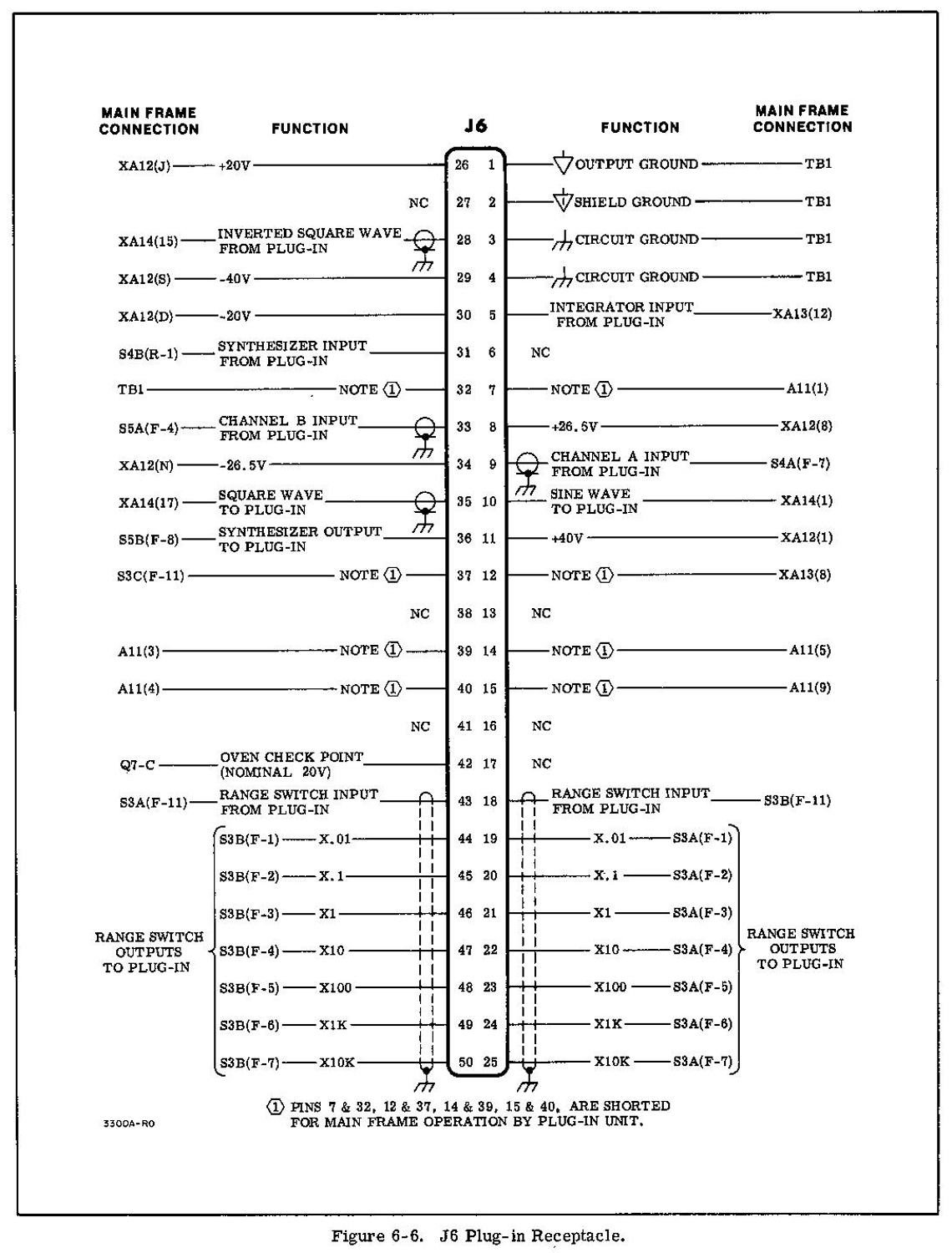
6-5. PLUG-IN RECEPTACLE.
6-6. Figure 6-6 shows the connections brought out from the main frame of the 3300A for use with plug-in units».
§§§
Per consultare le altre due parti scrivere “3300A” su Cerca. Per consultare le schede dello Sweep Plug-In 3305A scrivere “3305A”.
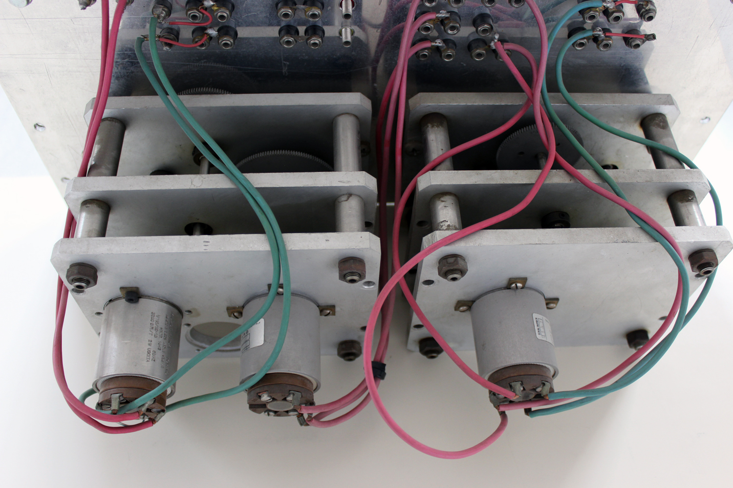
Foto di Claudio Profumieri, elaborazioni e ricerche di Fabio Panfili.
Per ingrandire le immagini cliccare su di esse col tasto destro del mouse e scegliere tra le opzioni.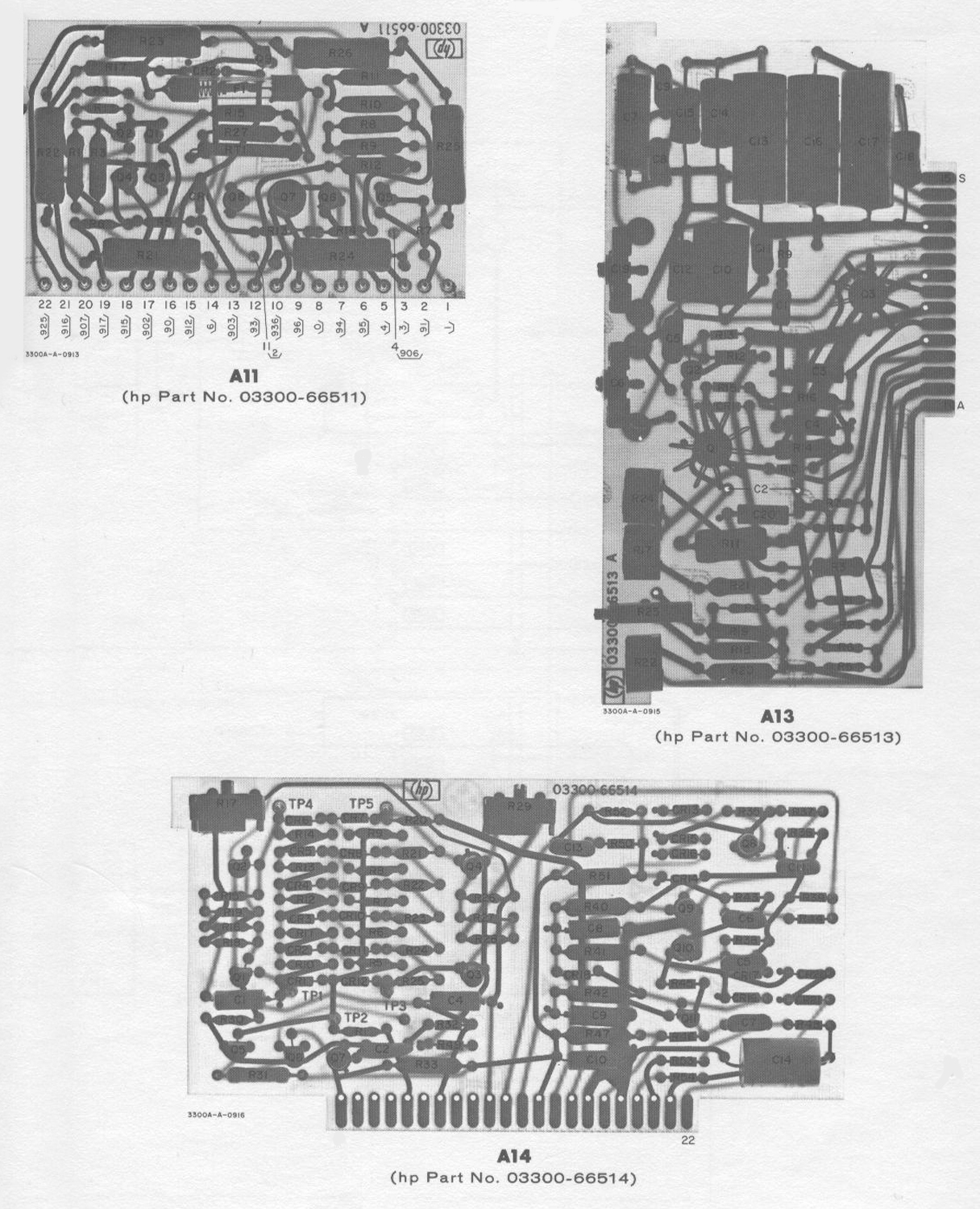


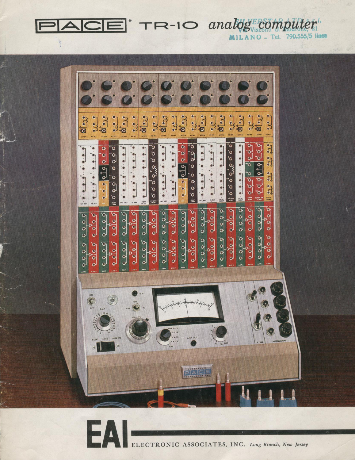
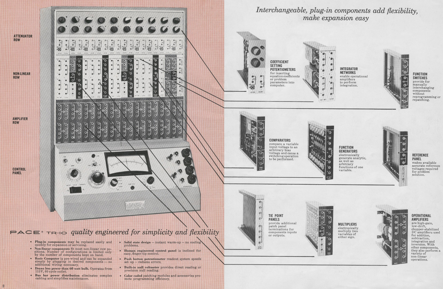
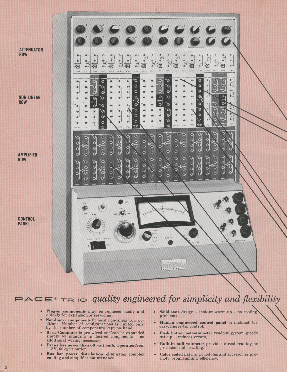
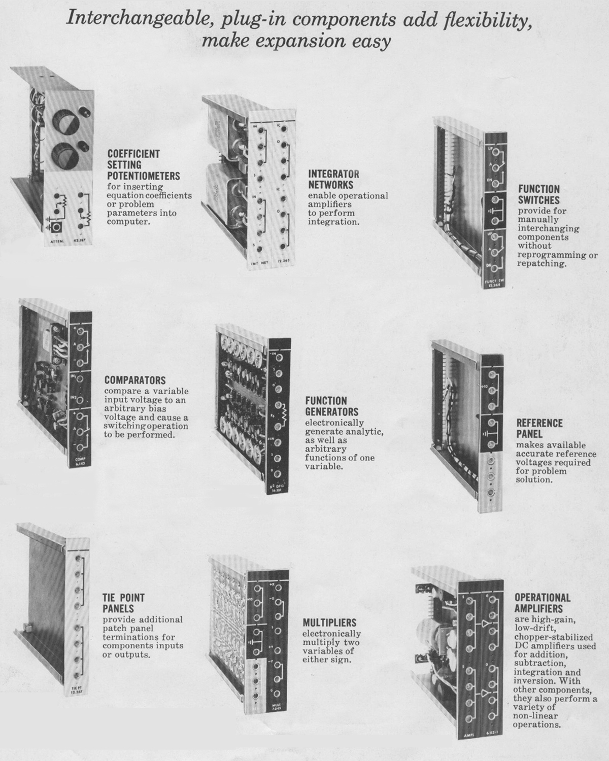
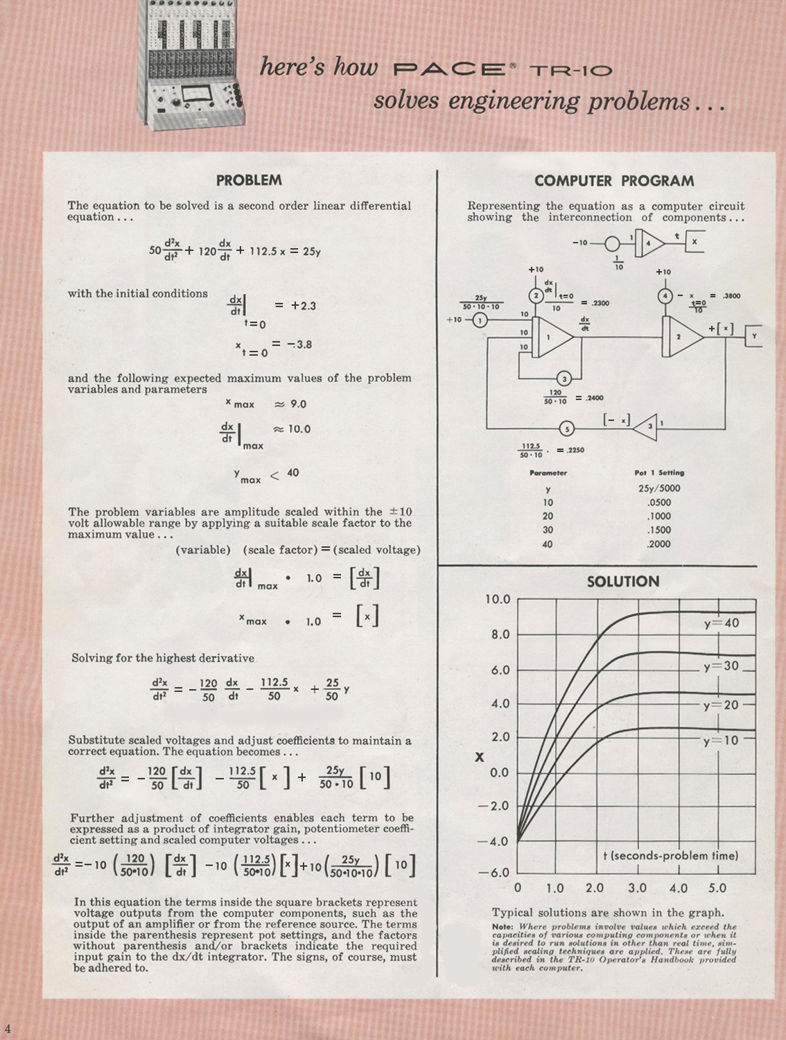
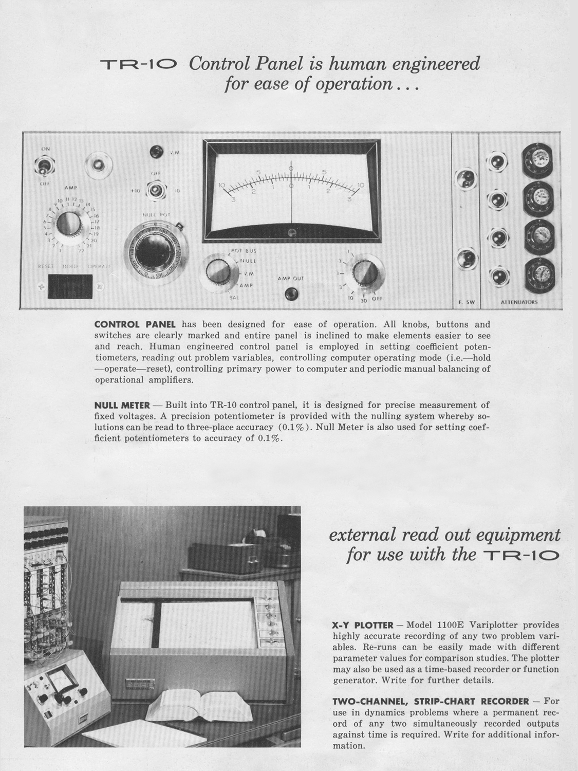
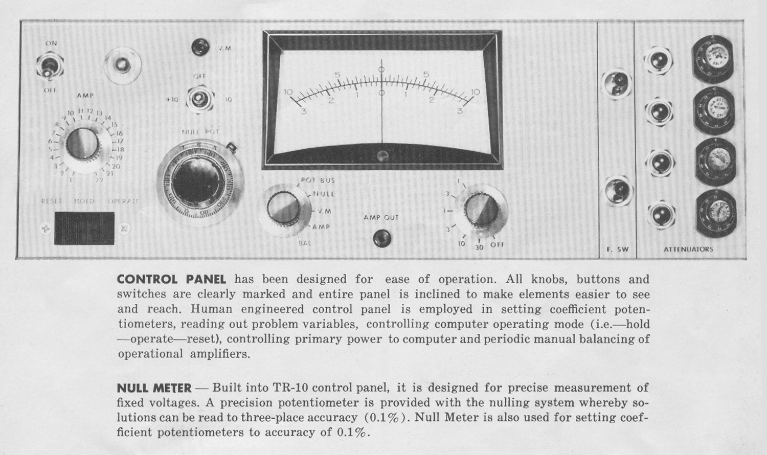
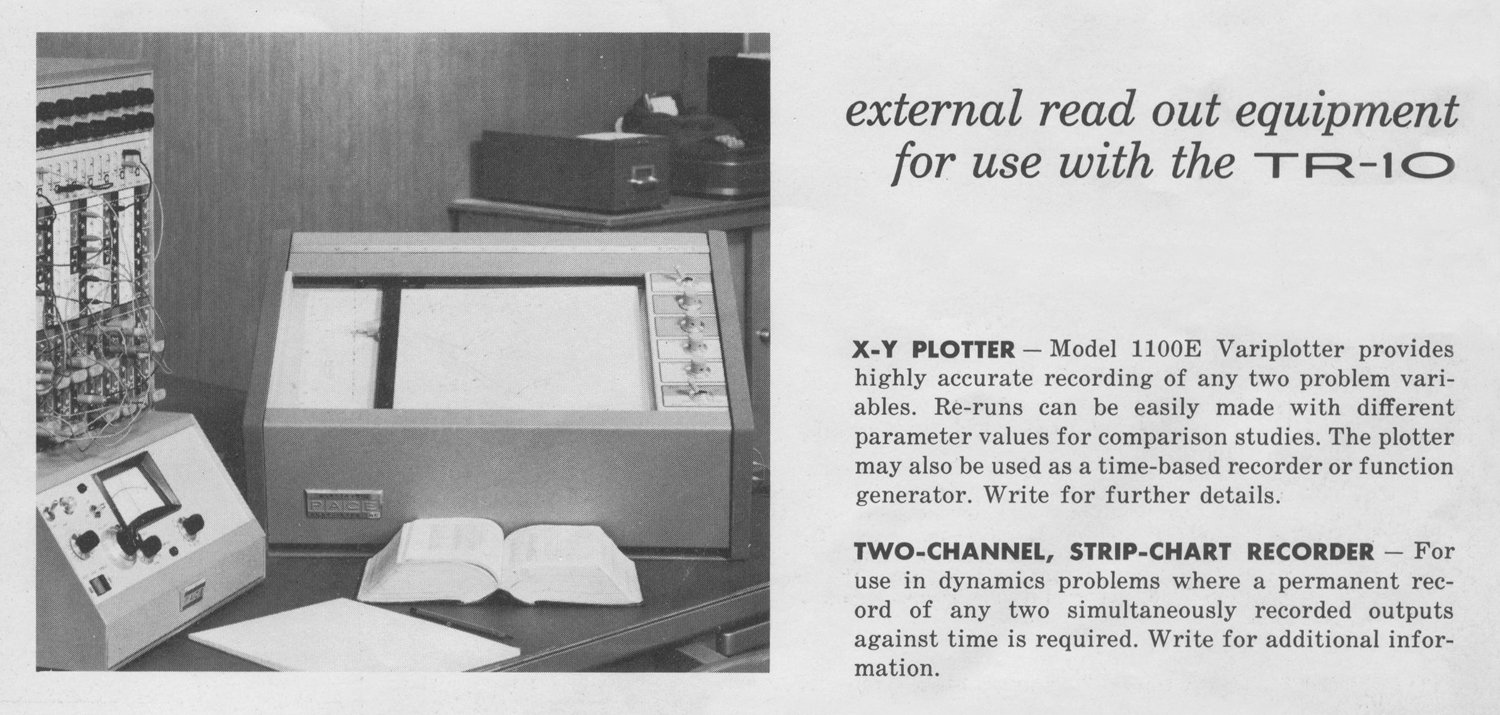
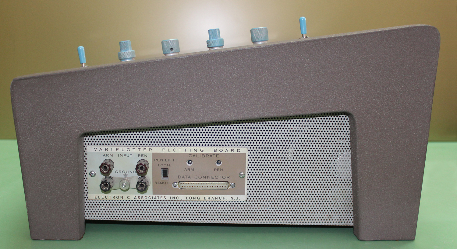
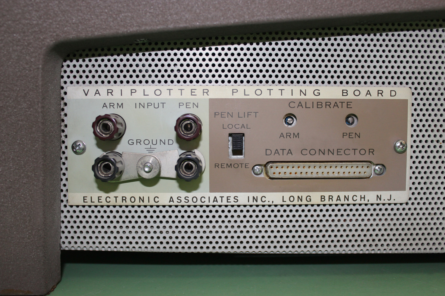
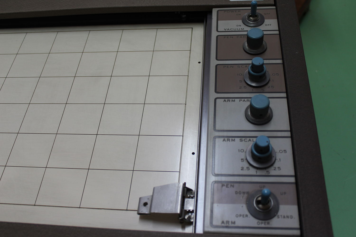
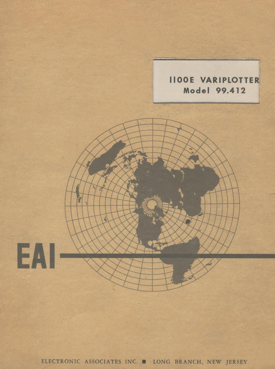
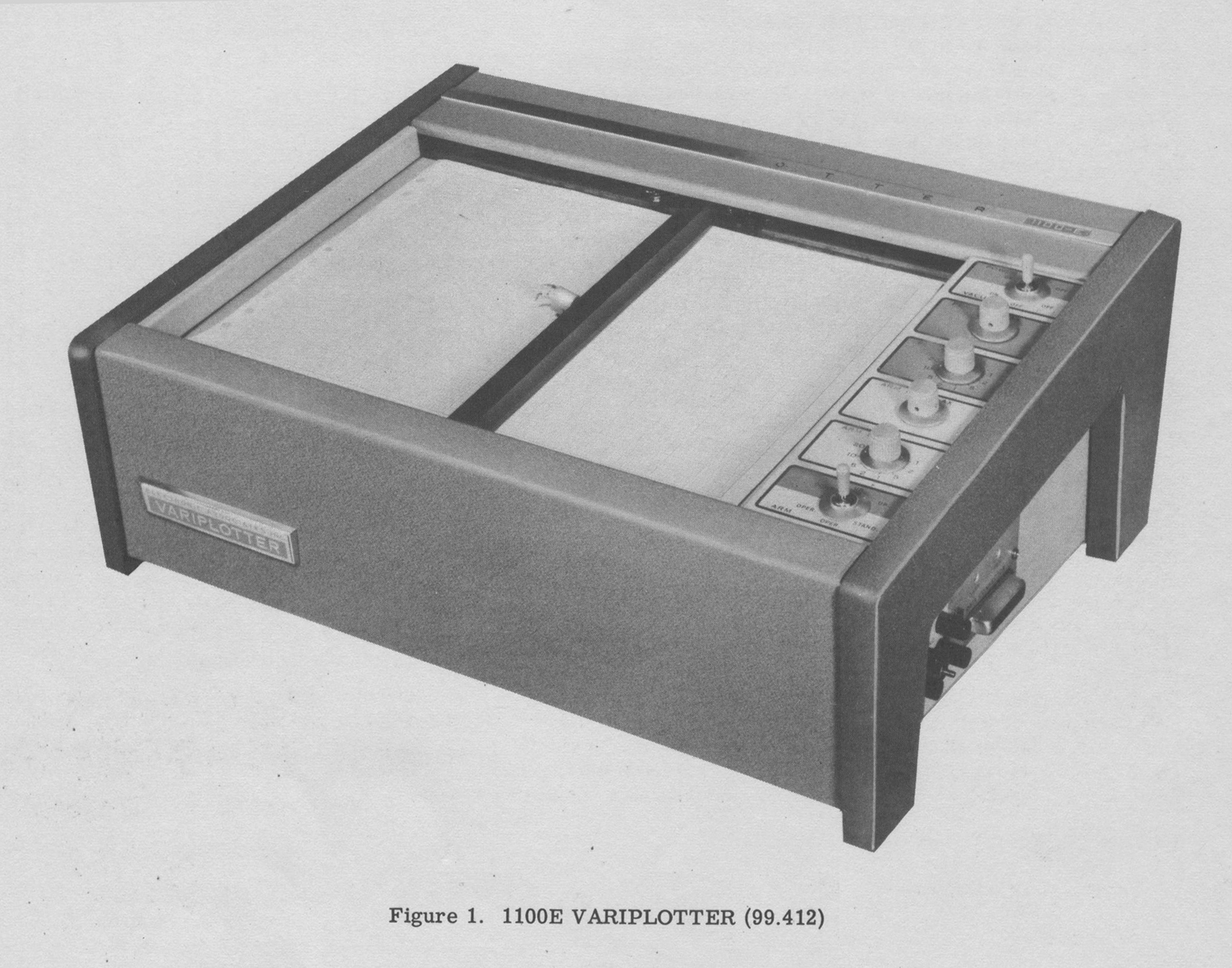
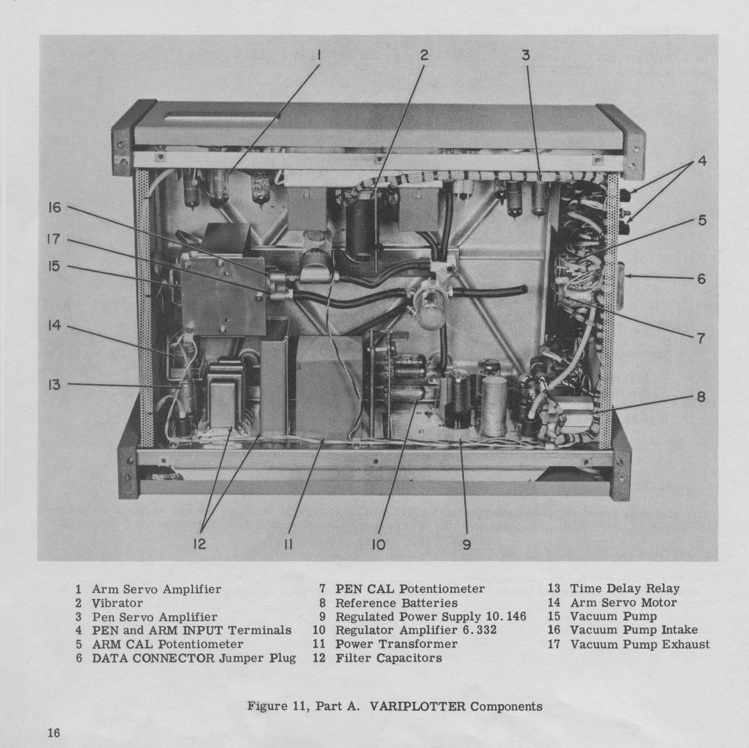
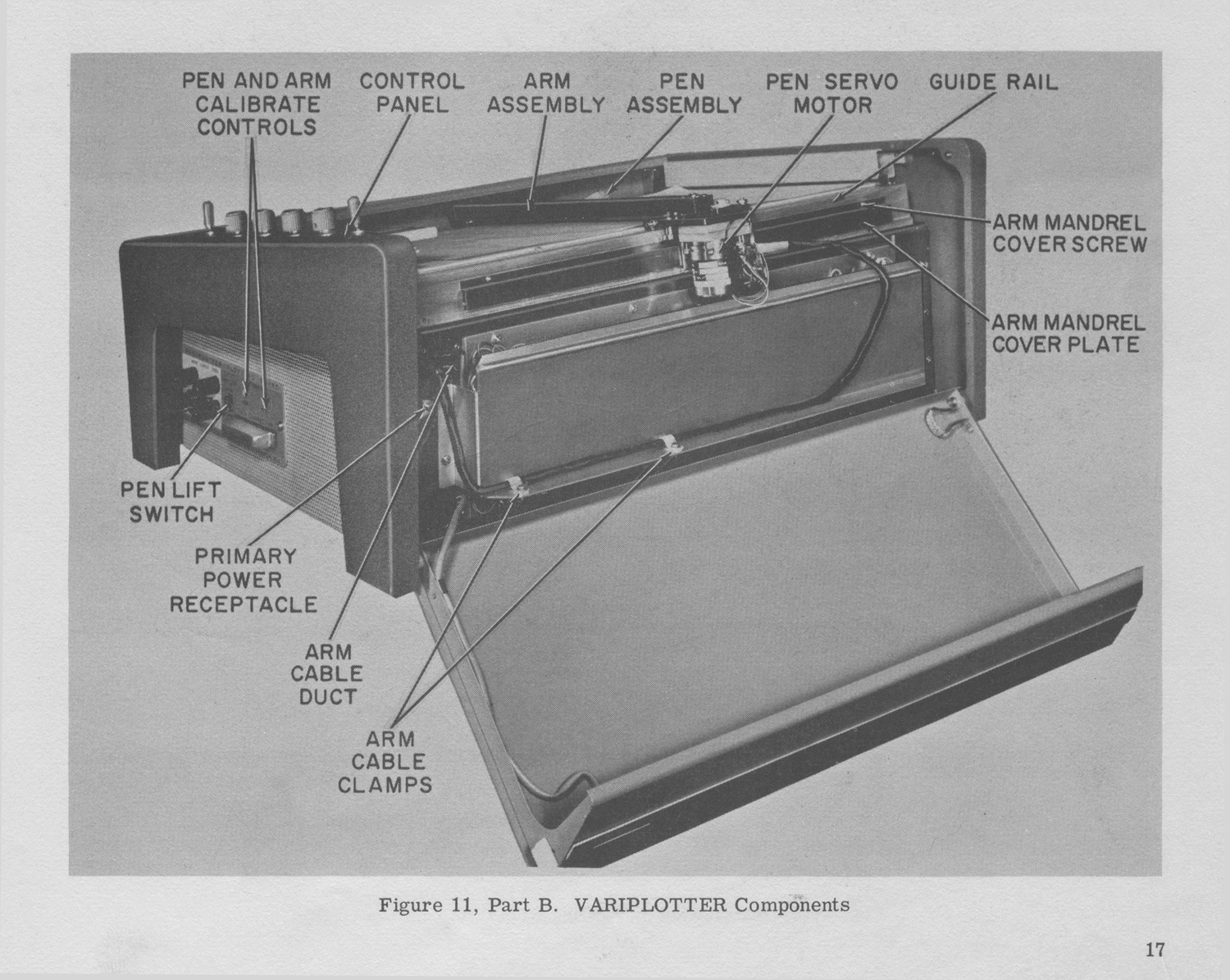
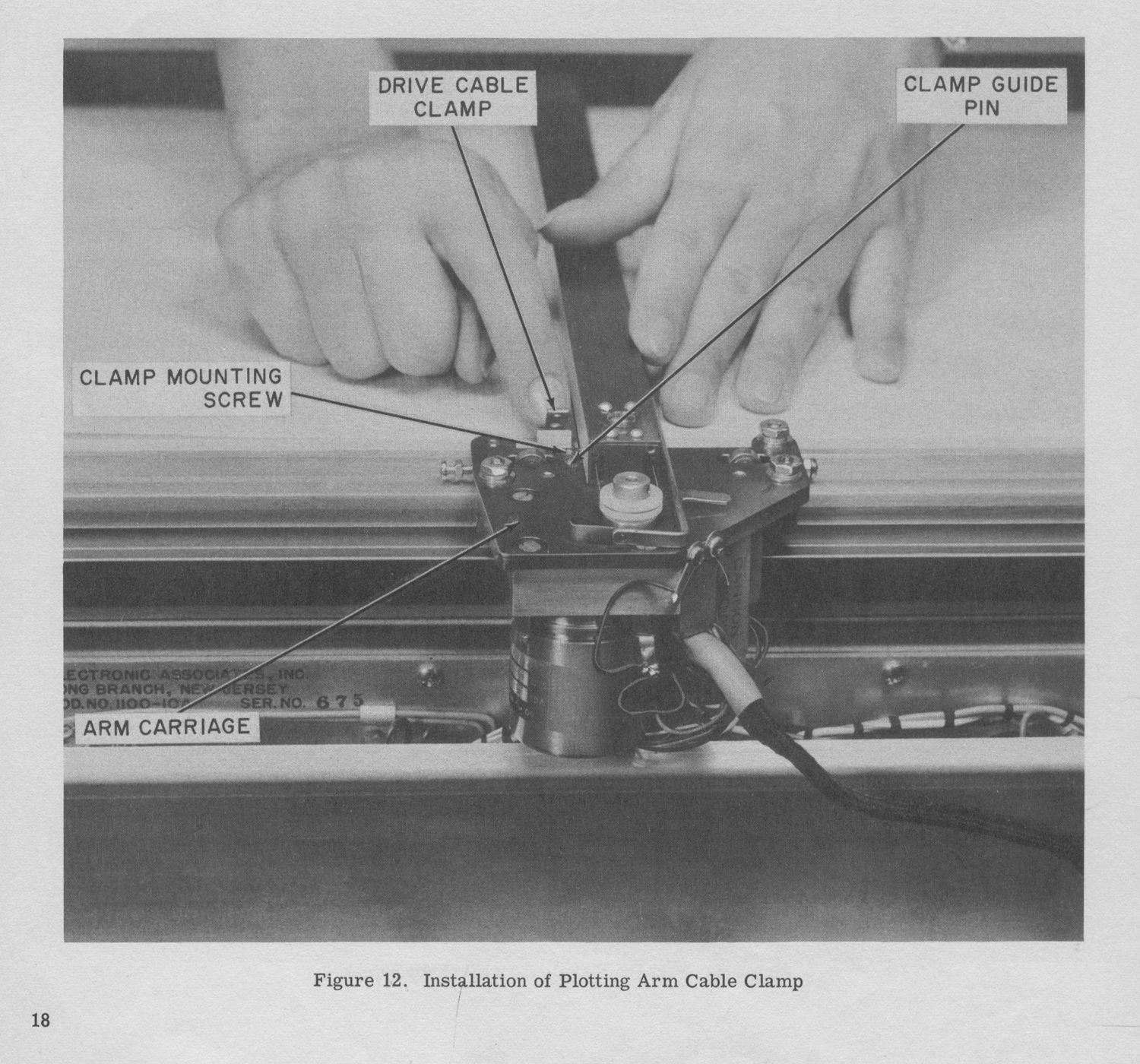
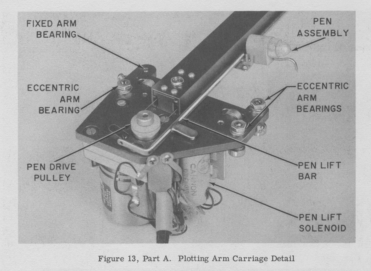
 Calcolatore analogico EAI PACE TR-10 (Electronic Associates Inc.). Seconda parte.