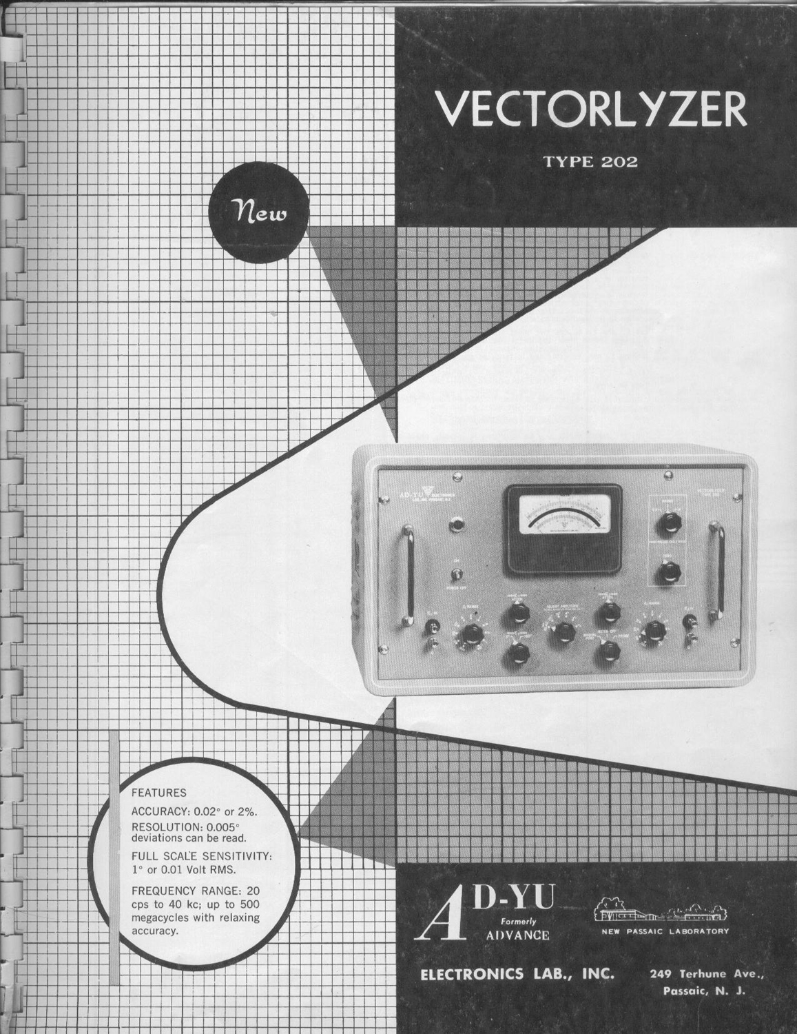
 Vectorlyzer Type 202 AD-YU Electronics Lab. Inc. Passaic, N. J. . Quarta parte.
Nell’inventario D del 1956, in data 28 maggio 1963, al n° 3285 si legge: “Ing. Mario Vianello – Milano. Vectorlyzer. Dest. Elettronica. ₤ 710.000” .
Il prof. Luigi Silenzi ricorda di averlo usato, ma alcuni di noi allievi dell’epoca non ne hanno memoria, forse perché è uno strumento per applicazioni veramente complesse che esulavano dai programmi di insegnamento.
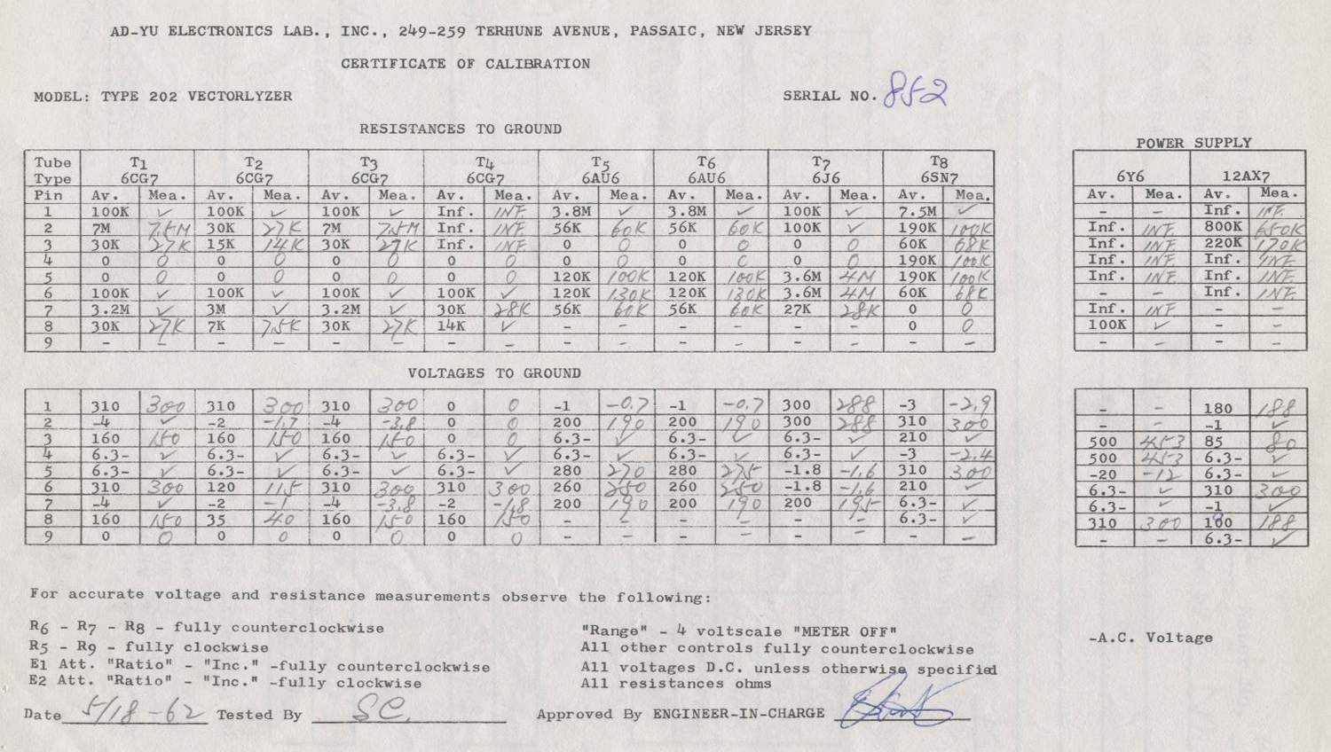
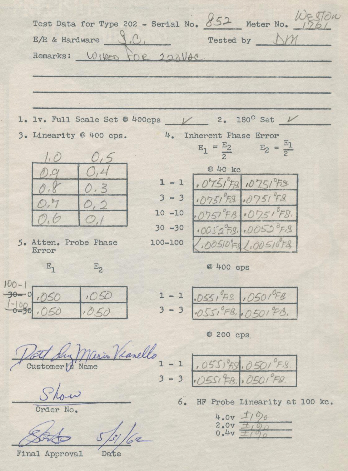
Abbiamo trovato negli archivi della Sezione Elettronica il manuale delle istruzioni originali risalente al marzo del 1961; in fondo al manuale vi sono due pagine, datate rispettivamente 18/05/1962 e 31/05/1962, dei collaudi a cui è stato sottoposto questo strumento.
Invece di trascrivere una traduzione affrettata, ed anche per mantenere l’efficacia dell’originale, ne riportiamo alcune parti in inglese.
§§§§§§§§§
PROCEDURES FOR MEASURING PHASE ANGLE ABOVE 100 KC:
The simplest method for phase measurement at high frequencies is by using the knowledge of simple geometry. The procedure is as follows:
1.Turn “BINDING POST, METER OFF, PROBE” switch to “PROBE”. Zero set the meter with both probe terminals shorted to ground. In Fig. 10, apply E1 to A and terminate E1 at C apply E2 at B and terminate E2 at D. Then read E2-E1 on panel meter.
2.Remove E2 and terminate E2 source with the same terminating resistor as at D.
3.Ground B of Fig. 10, read E1.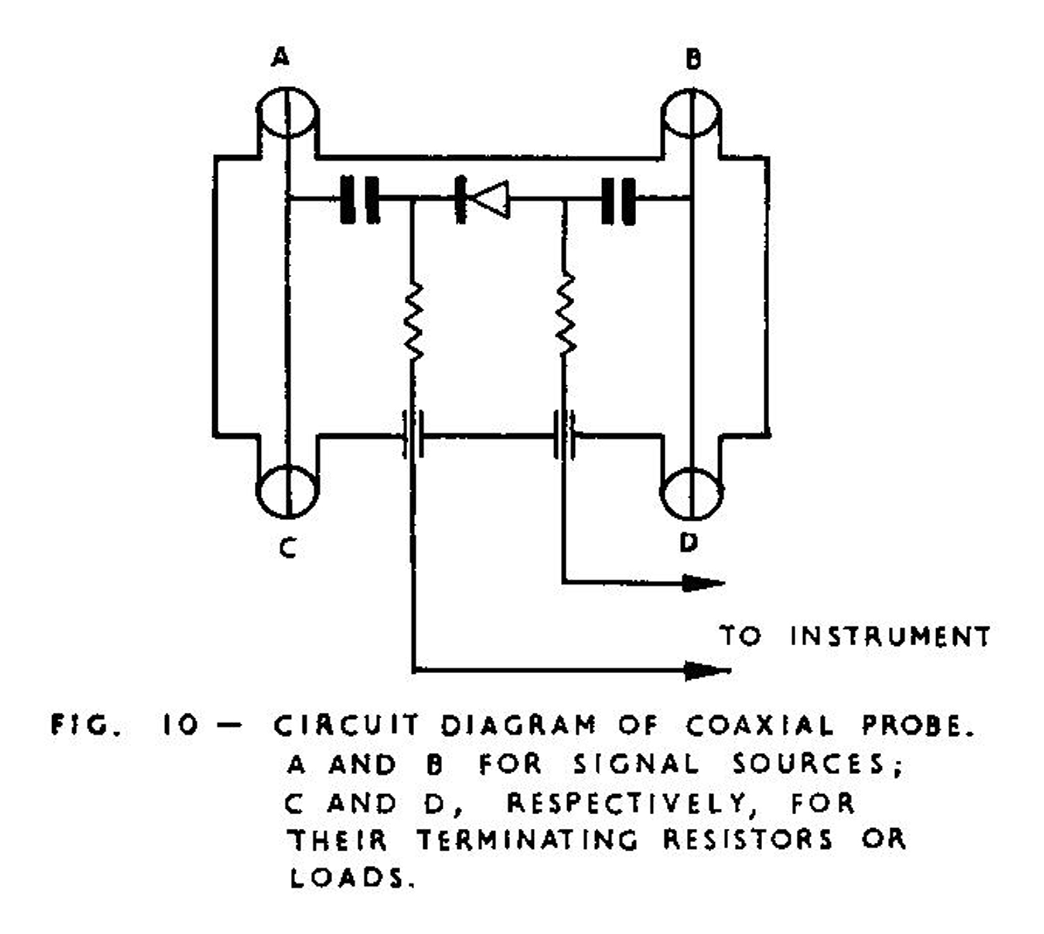
4.Remove E1 from A and terminate E1 source with same terminating resistor as at B. Then ground A of Fig. 10, read E2.
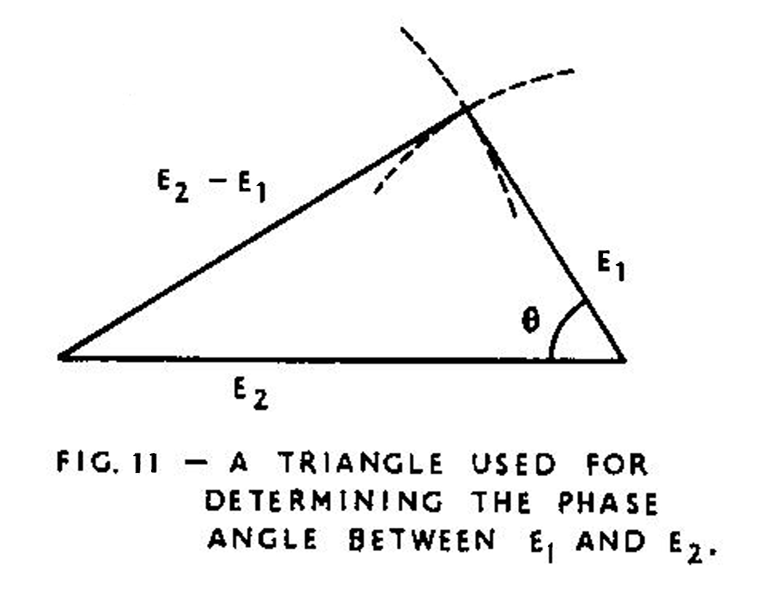
5.Draw a triangle with E1, E2, and E1-E2 as its three sides, as shown in Fig. 11.
6.Determine the phase angle between any two voltages by using the triangle of Fig. 11 with a protractor.
 MEASURING SMALL PHASE ANGLE ABOVE 100 KC:
Phase angles below 20° can be measured accurately if the amplitude for one of the input voltages can be continuously adjustable without changing its phase. The procedure is as follows:
1.Connect the input voltage with fixed amplitude to one input terminal, and ground the other input terminal. Record the meter reading as E1.
2.Apply both input signals to the two input terminals of the probe for measuring the vector difference, E2-E1. Adjust the amplitude of E2 until the meter reading becomes minimum. Turn the “RANGE” switch to more sensitive position if needed.
3.The phase angle between E1 and E2 is equal to the meter reading divided by a factor 0.0174 E1. The operating principle can be explained with the use of the following equation.
(7) |E0| = | E2| – |E1| = 2 |E1| sin (θ /2) for |E2| = |E1|
then
θ = 2 sin -1 (|E0| /2 |E1|) =|E0| / (0.0174 |E1|), when θ is small.
MEASURING VECTOR SUM OF TWO VOLTAGES:
For 20 cps to 100 kc, the operating procedure is very similar to measuring vector difference of two voltages except set “E1 SHIFT 0°-180°” to “180°” position, then the vector difference amplifier will become vector sum amplifier, and the meter will read the vector sum of two input voltages.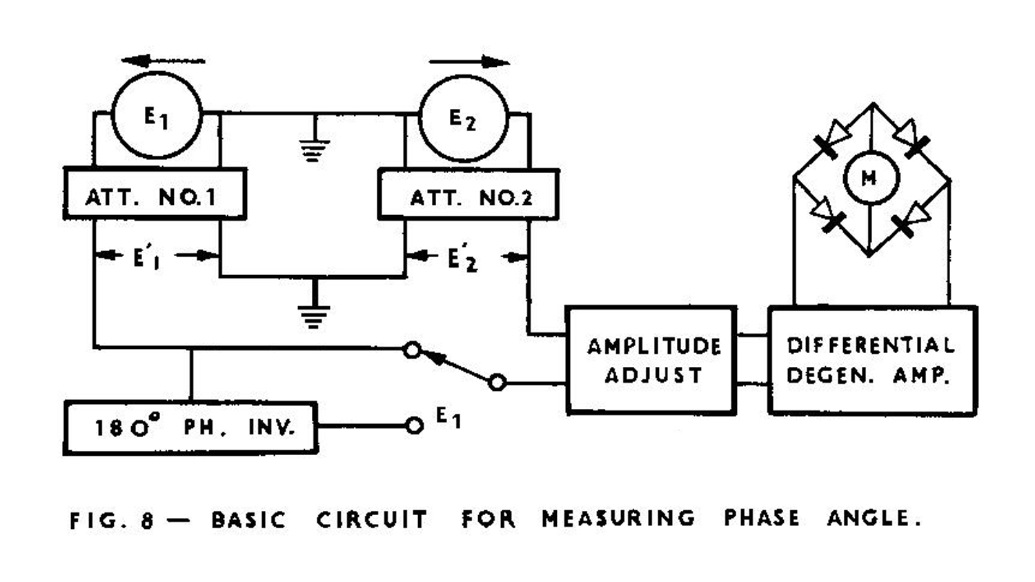 MEASURING COMPLEX COMPONENTS OF AN UNKNOWN VOLTAGE:
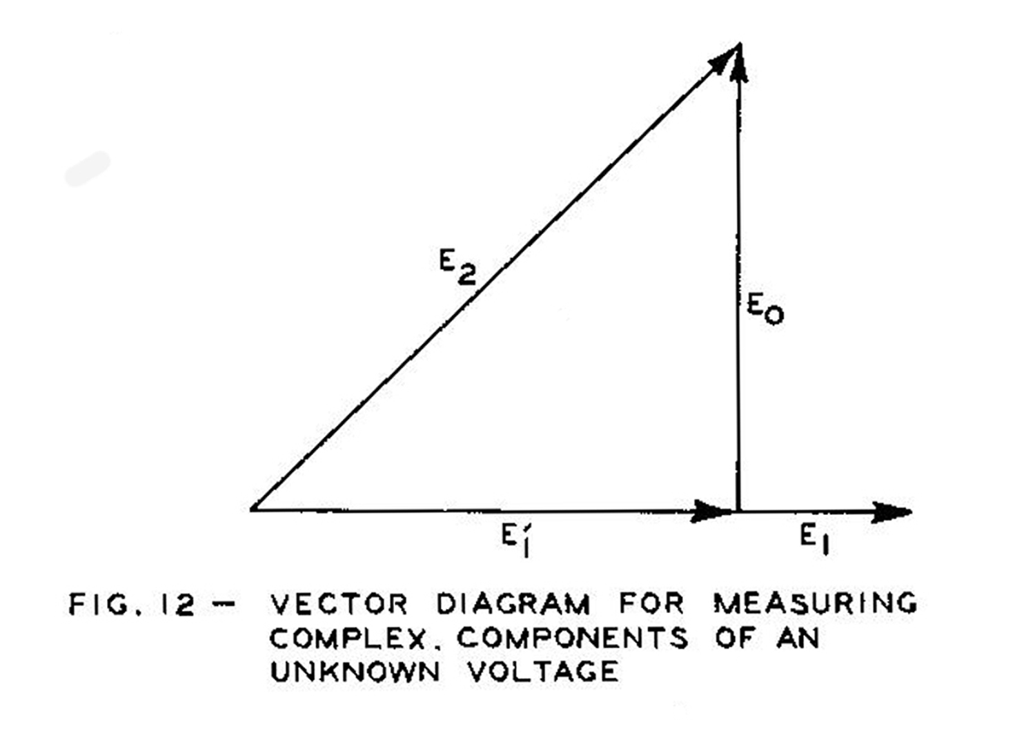
The vectorlyzer is a simple and convenient device for direct indication of the imaginary and real components of an unknown voltage in terms of a reference voltage. In Fig. 8, E1 and E2 are assumed to be the reference and unknown voltages respectively. Adjust the attenuator in E1 channel until the deflection of the output meter reaches a minimum. To represent this condition, a vector diagram is drawn in Fig. 12 for E1, E2 and E0. Symbol E0 denotes the reading of the output meter. Since these three vectors form a right triangle, the diagram indicates: (1) E0 equals the imaginary component of E2, and (2) E1 equals the real component of E2. Thus the meter reads directly the imaginary component after the attenuator in E1 channel has been adjusted for minimum meter reading. Then remove E2, ground E2 IN binding post, the meter now indicates directly the real component of E2. In case that the phase angle between the unknown voltage and the reference voltage is greater than 90 degrees, but less than 270 degrees, the preceding method of measuring complex components still remains useful when E1 is shifted 180 degrees with respect to E2 by means of inserting the phase inverter. Without inserting the phase inverter it would be impossible to reduce the indication of the output meter to a value less than the absolute amplitude of E2.
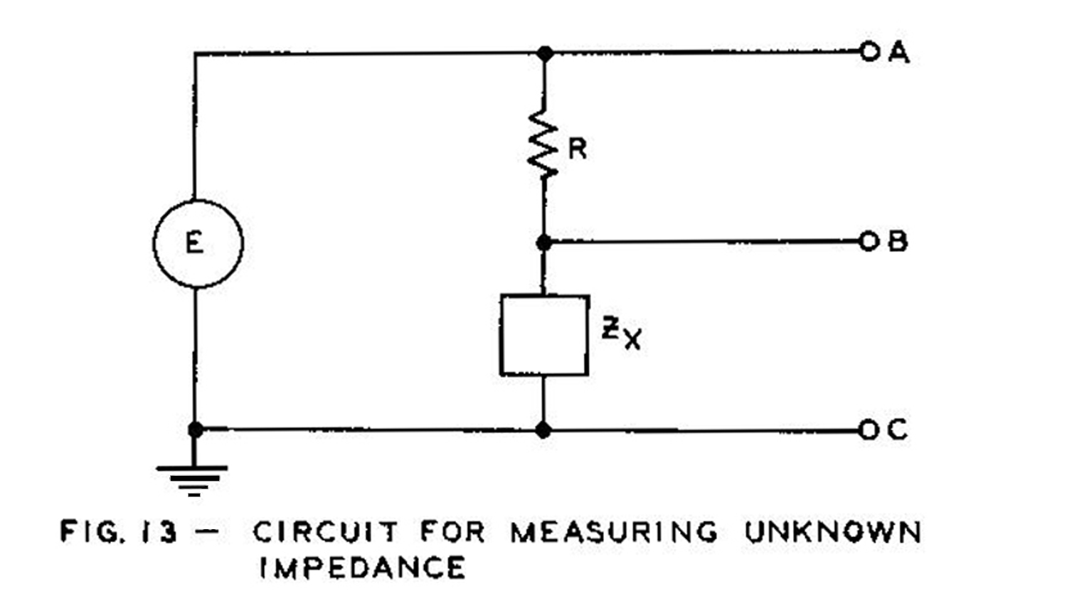
MEASURING UNKNOWN IMPEDANCE:
The magnitude and phase angle of an unknown impedance may be measured by using the arrangement shown in Fig. 13. ZX is the unknown impedance, R is a pure resistor with its value approximately equal to the magnitude of Zx, and E is an oscillator whose output is set within the scale of E1 and E2 range. The procedure is as follows:
1.Measure the phase angle between the applied voltage E and the unknown impedance Zx by means of the method described above.
2.Measure the amplitude of the applied voltage E.
3.Measure the amplitude of the potential drop across unknown impedance, EZx
4.Draw a triangle with phase angle θ measured in (1) and the voltages measured in (2) and (3). This triangle is shown in Fig. 14. Now a perpendicular can be drawn from the point A toward ER. The phase angle Φ can be measured on the triangle as the angle of the unknown impedance. The magnitude of the unknown impedance ZX = R(EZX/ER).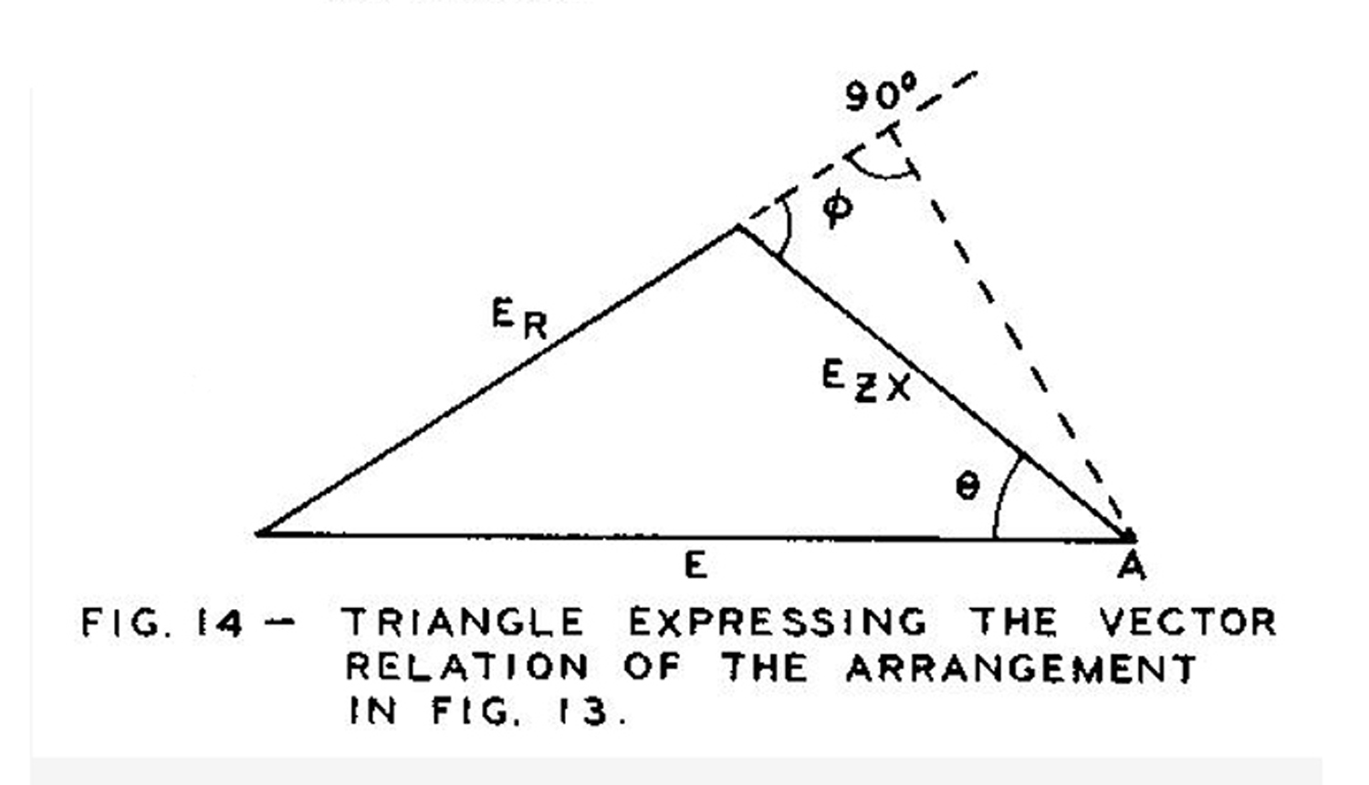 MEASURING RATIO OF TWO VOLTAGES:
Since Type 202 Vectorlyzer consists of two step attenuators and two continuously variable attenuators having adjustable attenuation from 1 up to more than 300, the ratio of two different voltages, |E2| / |E1|, can be conveniently measured. The procedure is as follows:
1.Set “AMPLITUDE SELECTOR” switch to “READ” position and set “E1 ATTENUATION RATIO” to a position slightly larger than the amplitude of E1. Set “E2 ATTENUATION RATIO” to ground.
2.Apply E1 to “E1 IN” binding post, then adjust “E1 ATTENUATION INC .” control until the meter reading equals “0.1” on the top (voltage) scale.
3.Remove E1 and connect E2 to “E1 IN” binding post. Now the meter indicates directly the ratio of E2 to E1 . If the indication is too small to read accurately, turn “E1 ATTENUATION RATIO” to lower attenuation. In this case, the reading should be multiplied by the reduction in attenuation ratio. If the indication is over scale, turn “E1 ATTENUATION RATIO” to higher attenuation and divide the meter reading by the corresponding increase in attenuation.
§§§§§§§§§
In questa parte abbiamo riportato la seconda copertina del manuale e le due pagine dei collaudi.
Abbiamo omesso volutamente la parte del manuale di istruzioni riguardante le note di manutenzione.
Le figure sono state opportunamente ingrandite.
Per consultare le altre schede scrivere “Vectorlyzer” su Cerca.
Foto di Claudio Profumieri, elaborazioni e ricerche di Fabio Panfili.
Per ingrandire le immagini cliccare su di esse col tasto destro del mouse e scegliere tra le opzioni.