 Precision Phase Generator type 208A AD-YU Electronics, Lab Inc. Passaic N.J. . Terza parte.
Nell’inventario D del 1956, in data agosto 1964, al n° 3756 si legge: “Ing. MarioVianello. Milano. Circuito sfasatore “AD-YU” mod. 208A. Destinazione RAD. ₤ 720.000”.
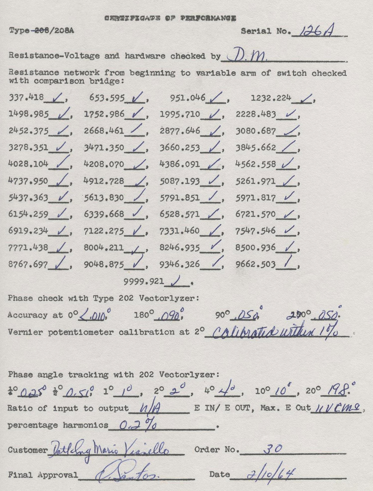
Uno scrupolo filologico sulle date si presenta quando si legge che la prova da parte del customer Dott. Ing. Mario Vianello è del 10 ottobre 1964.
Dopo aver pubblicato le prime due parti abbiamo rinvenuto ulteriori istruzioni dello strumento che abbiamo riportato qui di seguito.
§§§
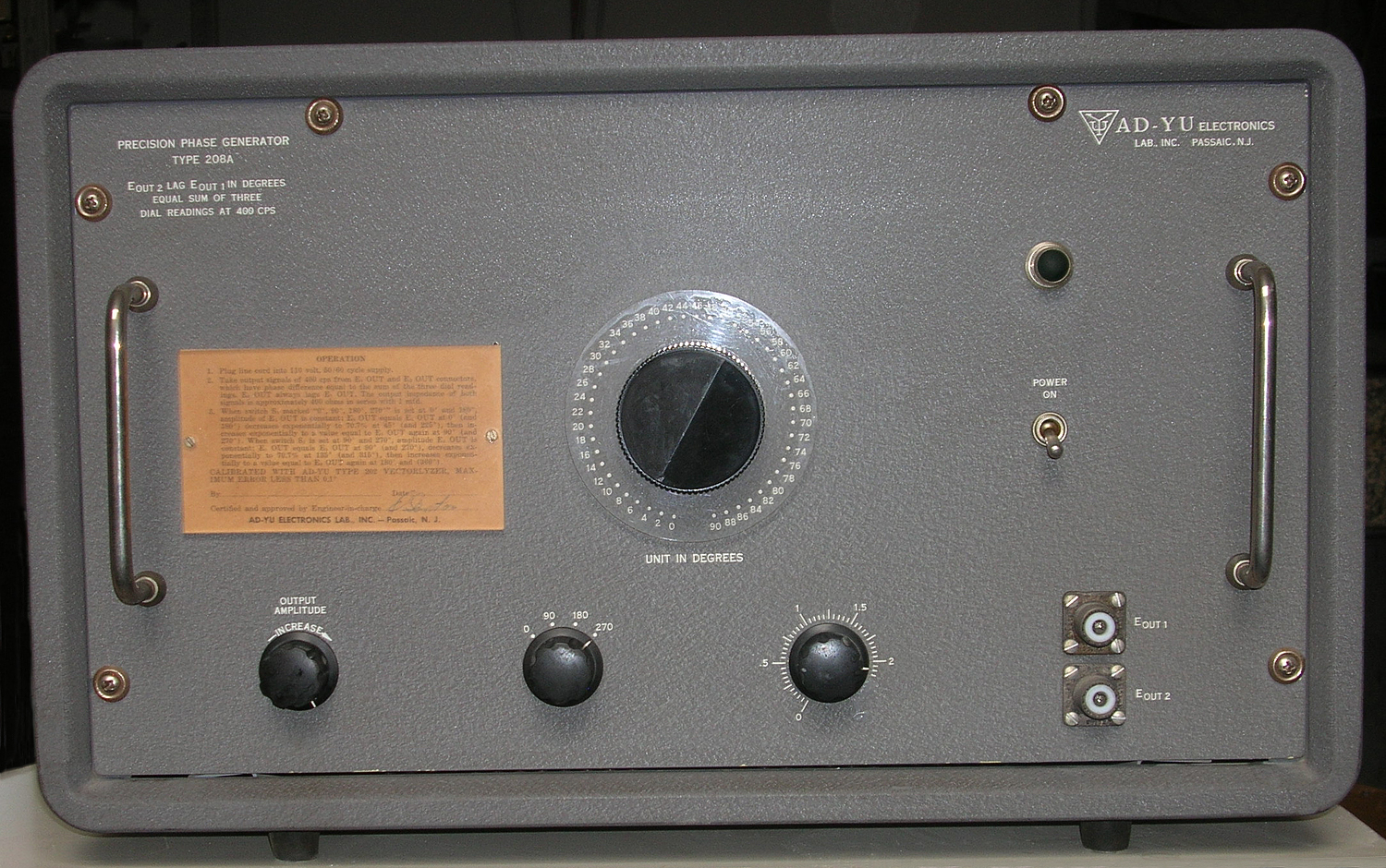
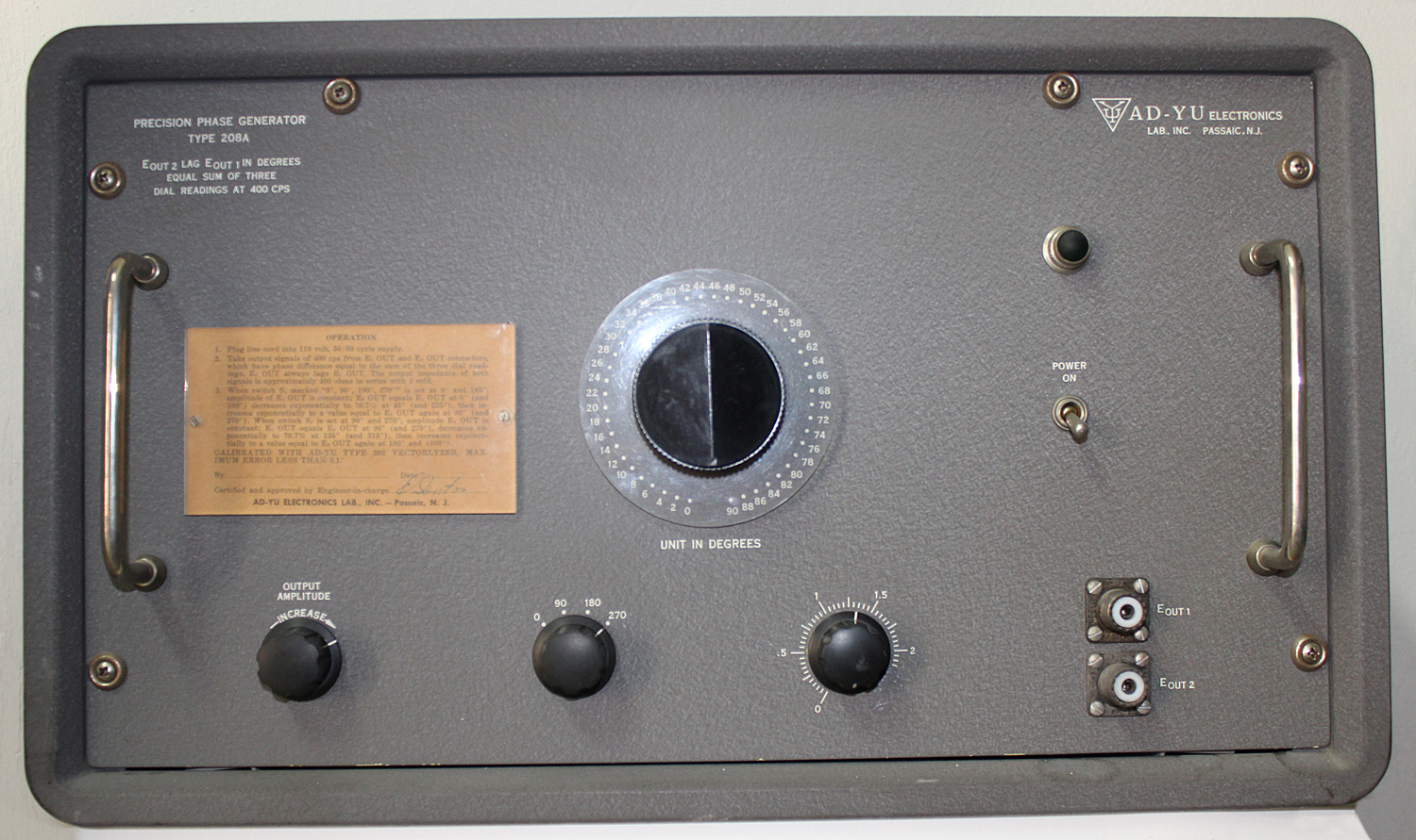
Questa è la traduzione della scritta posta sulla targhetta nella parte anteriore dello strumento (vedere la prima parte).
«Dott. Ing. Mario Vianello – Milano
ISTRUZIONI PER L’USO DEL “PRECISION PHASE GENERATOR” “AD-YU” tipo 208°.
1) Collegare il cordone di alimentazione alla rete 220V, 50/60 Hz.
2) Prelevare l’uscita dei segnali di 400 Hz ai connettori E1 out E2 out, i quali hanno una differenza di fase pari alla somma delle indicazioni delle 3 manopole:
l’uscita E2 ritarda anche E1
l’impedenza dei due segnali [delle due uscite N.d.R.] è circa 400 ohm in serie ad 1 μF.
3) Quando il commutatore segnato 0°-90°-180°-270° è posizionato a 0° e 180° l’ampiezza dell’uscita E1 è costante; l’uscita E2 è uguale ad E1 a 0° e 180°, diminuisce esponenzialmente a 70,7% a 45° (e 225°), quindi aumenta esponenzialmente al valore uguale ad E1 a 90° ( e 270°).
Quando il commutatore S1 è posizionato a 90° (e 270°) l’ampiezza dell’uscita E2 è costante; l’uscita E1 è uguale ad E2 a 90° (e 270°) diminuisce esponenzialmente del 70,7% a 135° (e 315°) quindi aumenta esponenzialmente al valore di E2 a 180° (e 360°)».
§§§
Segue una nota scritta a mano: “Istruzioni più dettagliate”. Istruzioni che riportiamo qui di seguito.
§§§
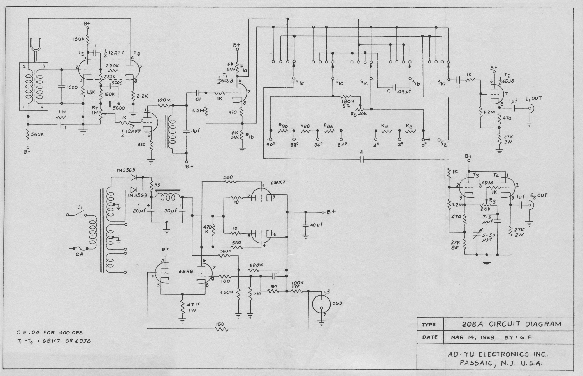
« COMPLETE CIRCUIT DIAGRAM:
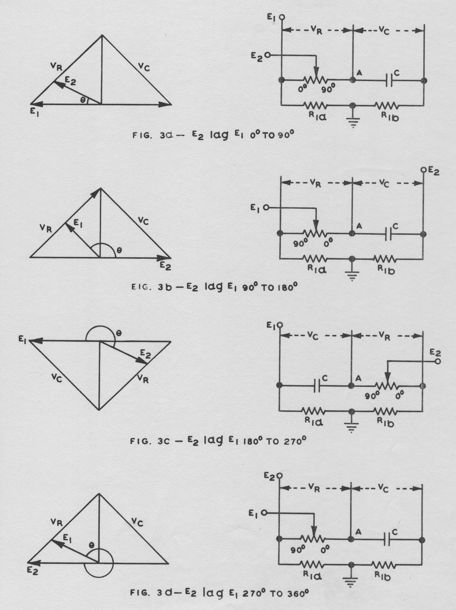
Fig. 1 shows a complete circuit diagram. T1 is used as phase inverter to provide two equal voltages with 180° phase difference when the value of R1a is exactly equal to R1b. Switch S1 has five sections and is used to alter the connections of E1 OUT, E2 OUT, as described in Figs. 3a to 3d. By adjusting R1a exactly equal to R1b, VR will be exactly equal to Vc when RWC = 1 where W = 2π × signal
Frequency [ωRC N.d.R.]. T5, T6 and T7 are used in the tuning-fork oscillator circuit of Type 208A.
PANEL CONTROLS:
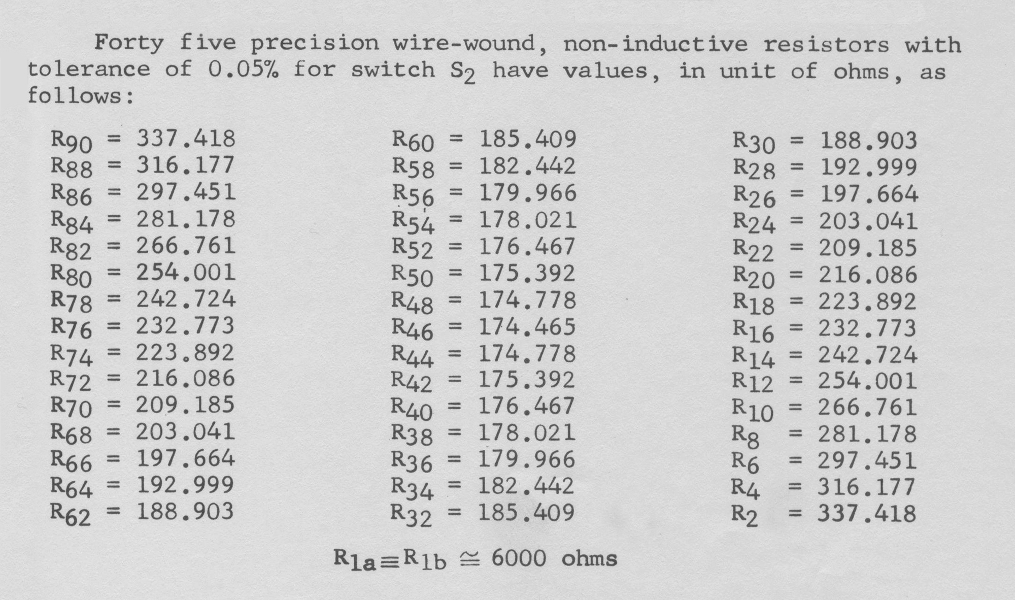
E IN – Binding post for connection of input signal (Type 208 only). 0, 90, 180, 270 degrees – Switch S1 in Fig. 1, a 5-pole, 4-position switch for providing phase shift of 0°, 90°, 180° or 270°. 0 to 90° dial – Switch S2 in Fig. 1, a 1-pole, 46-position switch for providing 0 to 90° phase shift in step of 2°. 0 to 2.5° potentiometer – Potentiometer R3 in Fig. 1, a 25K potentiometer for providing 0 to 2.5° continuous phase shift. E1 OUT, E2 OUT – Two UHF connectors for obtaining two output voltages with precision phase shift.
OUTPUT AMPLITUDE INCREASE – Potentiometer R7 in Fig. 1, a 1-meg potentiometer for adjusting the output amplitude for 0.5 volt to 10 volts rms (Type 208A only).
OPERATING PROCEDURE:
1. Plug line cord into 110 volt, 50/60 cycle supply, and apply a sine wave signal voltage with negligible harmonics and noise, not larger than 15 volts rms, to E IN binding post of Type 208. Type 208A has tuning-fork oscillator and does not require external oscillator.
2. Take output signals from E1 OUT and E2 OUT connectors. The phase shift between these two voltages is equal to the sum of the three dial readings at 400 cycles. The output impedance of both connectors is approximately 300 ohms in series with 1 μfd.
3. When the frequency of applied signal to Type 208 is slightly deviated from 400 cycles, it is suggested to use the method described under FREQUENCY VARIATION for adjusting potentiometer R5 located at the top of the chassis.
Type 208 may be used as phase shifter after the insertion phase shift of the instrument has been found with a phase meter. In this case, for 0 — 90° and 180° – 270° phase shift, take the output voltage from E2 connector.
CALIBRATION:
The accuracy of the instrument can be maintained by skillful calibration with Ad-Yu Type 202 Vectorlyzer, which has full scale sensitivity of 1°.
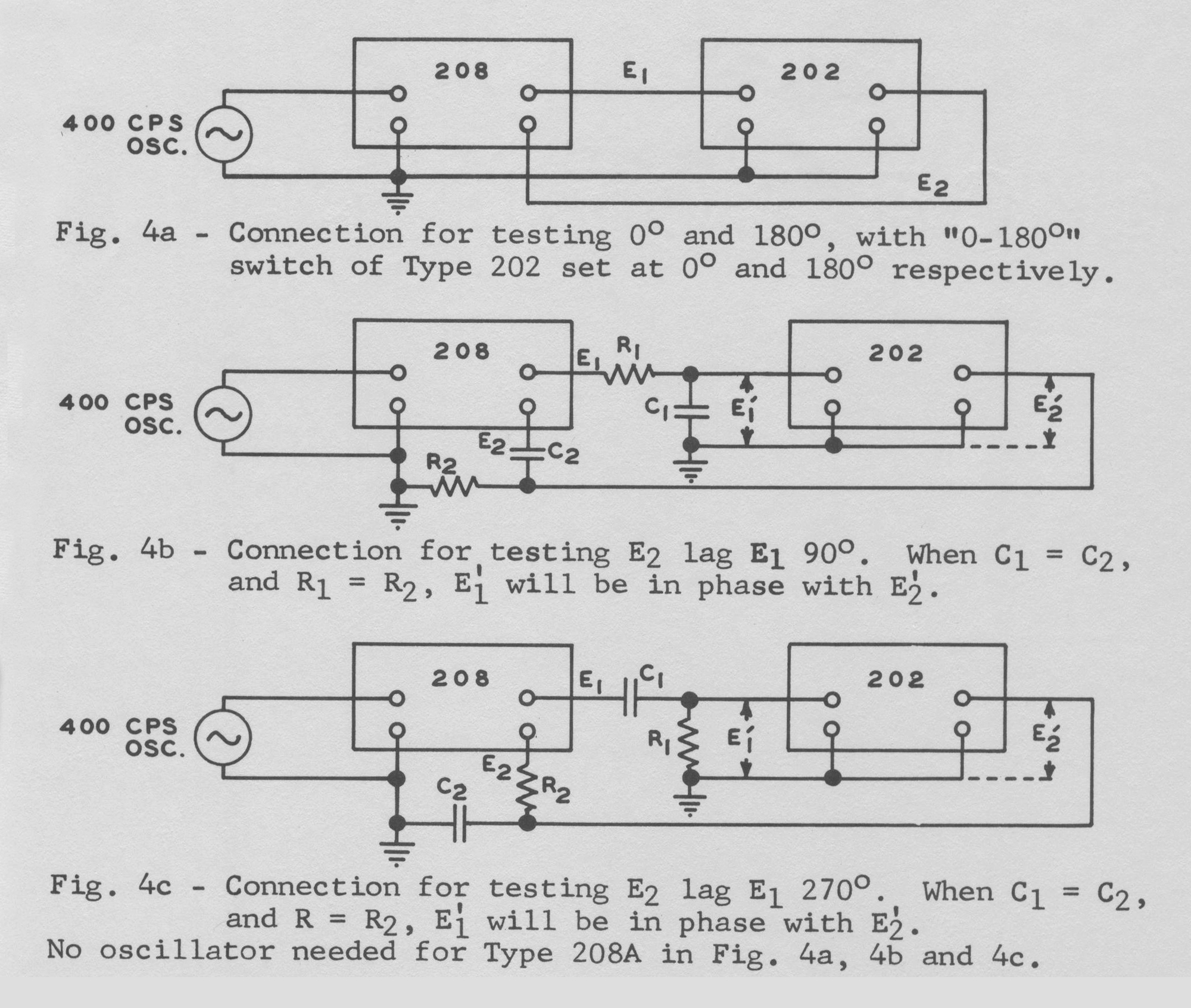
For calibration of 0°, the connection is shown in Fig. 4a. For calibration of 180°, Fig. 4a also can be used with the exception of introducing 180° phase shift in Type 202. Harmonics and hum will be added on the panel meter of Type 202, instead of cancelled out as in the case of 0°. Therefore, the signal applied to Type 208 must be
free from harmonics and noise to obtain satisfactory results. Type 208A has tuning-fork oscillator and filter for generating pure sine wave at exact frequency. For calibration of 90° and 270°, the connection is shown in Figs. 4b and 4c, respectively. Potentiometer R5 located at the top of the chassis of Type 208 or Type 208A can be adjusted in order to give 0° indication in Type 202 Vectorlyzer.
FREQUENCY VARIATION (TYPE 208 ONLY):
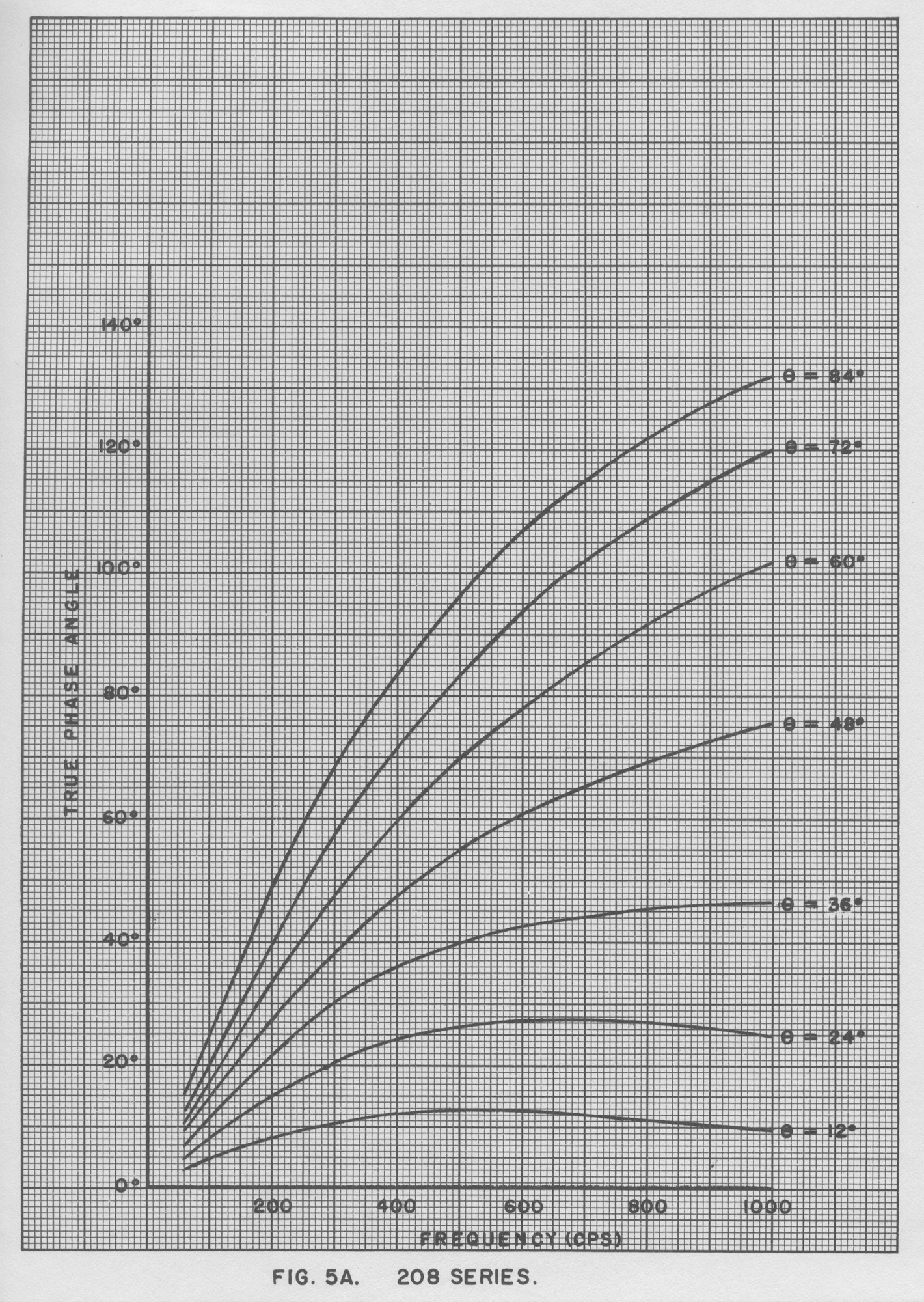
When the input signal of Type 208 is slightly deviated from 400 cycles, potentiometer R5 should be adjusted in order that RWC = 1 in Fig. 3. The arrangement in Fig. 4b can be used to test the condition of RWC = 1, at which E’1 and E’2 are exactly 90° apart, If the input signal frequency of Type 208 is far from 400 cycles and the range of potentiometer R5 is not sufficient to produce the condition RWC = 1 in Fig. 3, it is suggested to use the curves shown in Fig. 5 for correction of the dial reading. These curves show the
correct phase reading for frequency variation from 60 cycles to 1000 cycles.

VARIATION OF OUTPUT SIGNAL AMPLITUDE:
When switch S1 of Fig. 1 (0°, 90°, 180°, 270°) is set at 0° and 180° positions, the amplitude of E1 OUT is constant and the amplitude of E2 OUT varies according to Equation (1). When switch S1 is set at 90° and 270° positions, the amplitude of E2 OUT is constant and the amplitude of E1 OUT varies according to Equation (2).
(1) E2 OUT = E1 OUT/(sinθ + cosθ) for 0°-90° and 180°-270°,
(2) E1 OUT = E2 OUT/(sinθ + cosθ) for 90°-180° and 270°-360°, where θ is the dial reading of 0° to 90° dial (switch S2) only».
§§§
Per consultare le altre due parti scrivere: “208A” su Cerca.
Foto di Claudio Profumieri, elaborazioni e ricerche di Fabio Panfili.
Per ingrandire le immagini cliccare su di esse col tasto destro del mouse e scegliere tra le opzioni.