
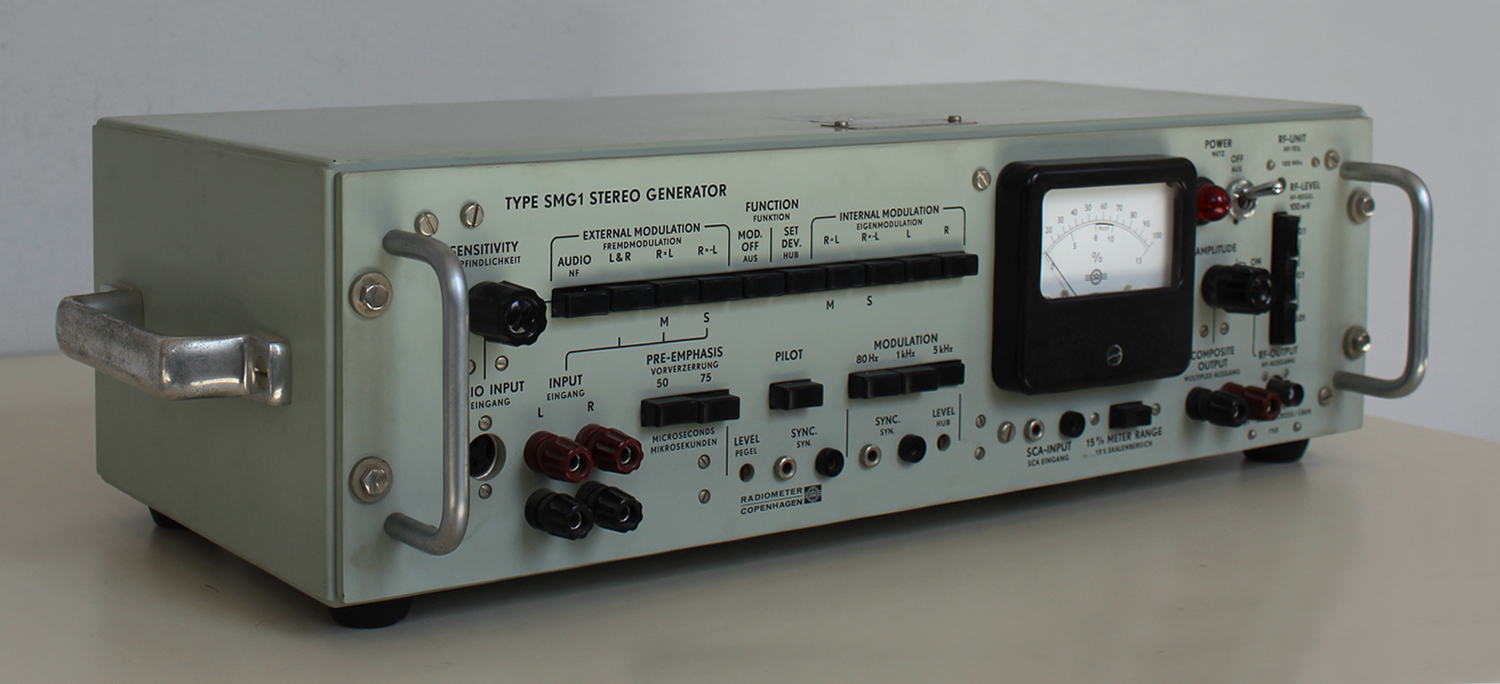
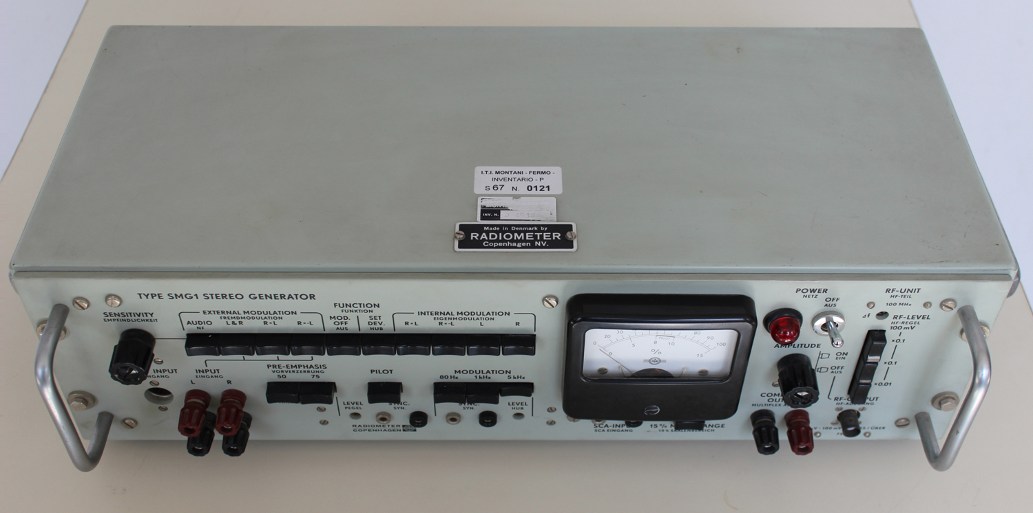
 Type SMG1 Stereo Generator Radiometer Copenhagen No. 164752. Seconda parte.
Per ingrandire le immagini cliccare su di esse col tasto destro del mouse e scegliere tra le opzioni.
Mentre scriviamo queste note non disponiamo dell’inventario dell’epoca nel quale si trova al n° D 4932.
Dal foglio di garanzia, riportato nella prima parte, risulta la data di acquisto: 5 novembre 1970. Inoltre vi si legge che l’importatore è U. De Lorenzo s.p.a. – Milano.
Nella Sezione Elettronica è custodito il manuale di istruzioni della ditta, del quale riportiamo alcune parti.
Il testo prosegue dalla prima parte.
§§§
«SWITCH MODULATOR
Two transistors, Q9 and Q10, are used in the switch modulator. The collectors are grounded, the bases are fed with balanced 38 kHz square-wave signals (the carrier signal), and the emitters are connected to the outputs of the input amplifiers via a resistive network. During one half-period Q9 is saturated and Q10 is cut off, whereas Q9 is cut off and Q10 is saturated during the other half-period.
The saturated transistor leads the output signal from the corresponding input amplifier to ground via a 200 Ω resistor, producing a multiplex signal at the centre of the resistive network (the arm of potentiometer R35). The multiplex signal from the modulator passes through a low-pass filter, which suppresses unwanted modulation products above 53 kHz.
The resistors R33 and R37 are necessary for obtaining a correct multiplex signal from the low-pass filter. A mathematical analysis shows that without R33 and R37 an MS-unbalance is present, which will cause LR crosstalk.
38 kHz CARRIER and T9 kHz PILOT SIGNAL EXCITER
76 kHz Crystal Controlled Oscillator
The 76 kHz frequency, which is basis for both the carrier and pilot signal frequencies, is crystal-controlled to secure a frequency stability better than 10-4.
The crystal operates as a series resonance circuit. The exact oscillating frequency is adjusted with an inductance, L5.
38 kHz Flip-Flop
The differentiated 76 kHz signal triggers a flip-flop, whose 38 kHz square-wave output is used as carrier signal to the switch modulator. Exactly equal half-periods of the carrier signal have been ensured by using a flip-flop triggered from a 76 kHz source.
19 kHz Flip-Flop and Low-Pass Filter
The differentiated 38 kHz square-wave triggers another flip-flop, whose output, after being filtered in a phase-stable low-pass filter, is used as the 19 kHz pilot signal. The pilot signal can be switched on or off with S101, and its level is set with a screw-driver-adjusted potentiometer R128. For synchronizing purposes it is accessible from the Sync. terminals.
PHASE-LINEAR LOW-PASS FILTER
The combined pilot and switched left/right signal passes through a 76 kHz rejector circuit to an emitter-follower Q101 .
The emitter-follower feeds a low-pass filter with extremely low phase- and amplitude-distortion up to 53 kHz to avoid MS-unbalance and consequential LR-cross-talk after decoding.
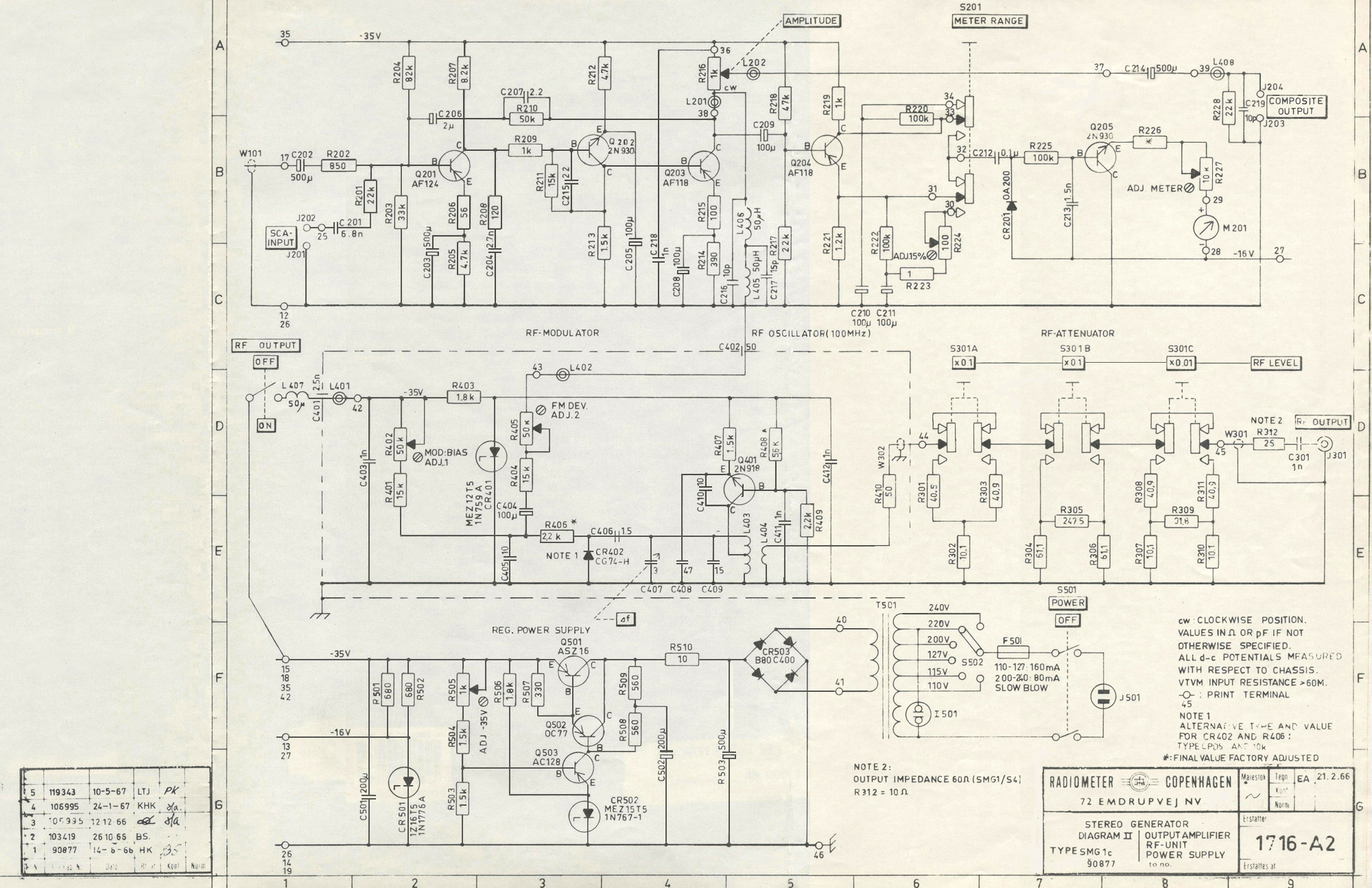
OUTPUT AMPLIFIER
The filtered signal is fed to the output amplifier, which is a 3-stage transistor amplifier with heavy feed-back in order to obtain high stability, low phase shift, low distortion and low output impedance in the frequency range 30 Hz to 75 kHz.
The SCA-Input is connected to the input of the output-amplifier through a capacitor and a resistor.
The amplifier output signal is fed to the Composite Output via a potentiometer R216 and a blocking capacitor C214.
Further, the output signal is fed to the RF-unit and to the meter circuit.
METER CIRCUIT
The meter must be peak-reading to ensure that the reading is a measure of the system peak-deviation, when the modulation signal is a complex signal.
The meter circuit consists of the transistor Q204, the peak-rectifier CR201-C212, the dc amplifier Q205, and the meter.
With the meter range switch S201 in its normal position (range 0-100%), the transistor Q204 will operate as an emitter-follower, supplying a very low feeding impedance to the peak-rectifier. Within the meter range 0-15%, Q204 is coupled as a common emitter with the output feeding the peak-rectifier. In this case the feeding impedance is too high to secure true peak-rectification of complex signals, so that this range should be used for measurement of the pilot signal only. If, however, this range is used for measuring a complex signal, the accuracy will be only about 5%.
The dc amplifier employs a silicon transistor Q205 with a very high current gain at small collector currents, which is necessary for true peak-rectification,
RF-UNIT
Oscillator
The 100 MHz oscillator employs transistor Q401 in a common base configuration. It has a tapped collector inductance and feed-back through capacitor C410. Small frequency changes may be made with trimmer C407, which is part of the tuning capacity.
The output is taken from a loop, coupled to the tuning inductance.
The RF-oscillator can be switched off by pulling the knob of the AMPLITUDE control.
FM Modulator
The frequency modulator is a reactance switch modulator, CR402-C406. The part of an oscillation period during which the capacitor C406 is connected across the tuned circuit is varied in accordance with the modulation signal fed to the diode CR402. In this way a truly linear
frequency modulation is produced.
Oscillator and FM modulator are housed in a shielding box.
RF Attenuator
The RF-signal passes an attenuator having three sections of 20, 20 and 40 dB attenuation. Each section can be switched in or out, so that the output voltages from 10 μV to 100 mV are obtainable in steps of 20 dB.
The impedance level is 75 Ω. The attenuator is protected against burn-out by a dc blocking capacitor C301. The RF-Output terminal is a type BNC connector.
REGULAT ED POWER SUPPLY
The generator can operate on the following nominal line voltages:
110, 115, 127, 200, 220, 240 volts. S502 is the line switch. The slow-blow fuse F501 protects the line transformer in case of a short-circuit.
The rectified voltage is regulated by a circuit employing three transistors and one zener diode. The regulated output voltage is set to -35 volts by the resistor R505. Some of the circuits operateon -16 volts, which are supplied via another zener diode, CR501, fed from the -35 volts supply.
The electronic regulation permits the instrument to be operated on line voltages deviating ± 10% from the nominal value.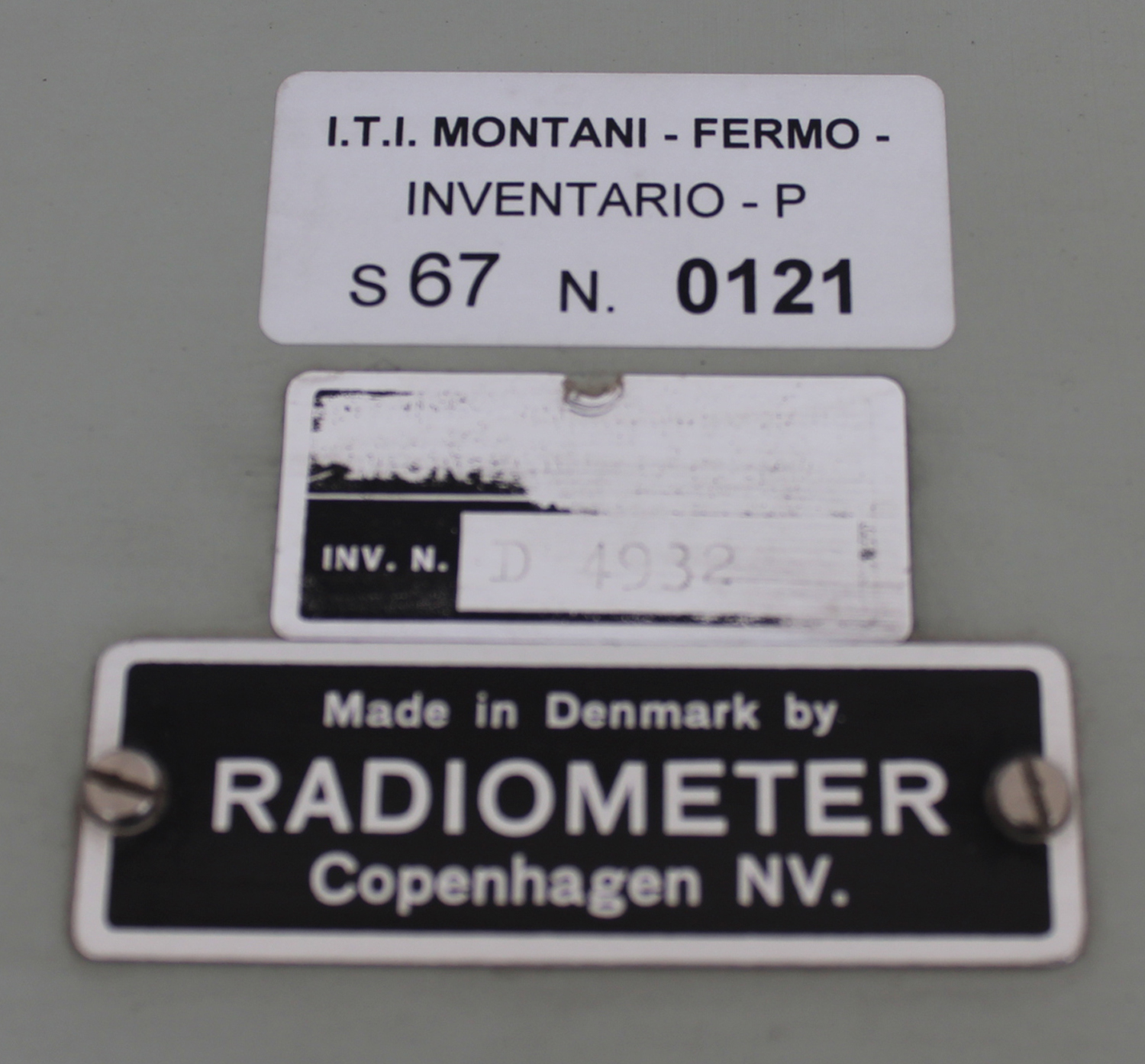 Section G. Maintenance
GENERAL
The Stereo Generator, type SMG1, has been designed to withstand rough treatment, but careful handling and proper use assure a long life and high reliability.
Necessary repairs should be carried out only by skilled personnel, provided with the proper equipment to ensure that the repairs are correctly made.
REMOVING THE GENERATOR FROM ITS CABINET
Detach the power cord and remove the four fixing screws at the sides of the front panel. The generator can now be pulled out of its cabinet.
REPLACEMENT OF COMPONENTS
General
Print boards with the transistors soldered directly in have been used throughout in the Stereo Generator. When servicing these circuits some precautions must be taken. Use a low-power soldering iron (65 watts maximum) to avoid damaging the print boards and transistors.
Most components are directly accessible. When this is not the case, loosen the frame carrying the print board of interest by removing a few screws, and then remove the print board.
Selected Components
The transistors Q9, Q10,and Q205 have been selected. If these transistors are to be replaced, the generator should be returned to the factory, or selected duplicates should be ordered from the factory.
All other components may be replaced by components of equal type and tolerance.
ADJUSTMENTS
External adjustment (accessible from the front panel
1) Meter, mechanical zero.
With the power switched off, adjust the screw on the meter to meter-reading 0. Switch on the power.
2) Modulating oscillator level.
Push button SET DEV. Set the screw-driver adjustment marked LEVEL below the MODULATION FREQUENCY buttons to full scale deflection (100%) on the meter.
3) Pilot signal level.
Push buttons MOD.OFF and PILOT.
Press button METER.
Set the screw-driver adjustment marked LEVEL below the PILOT button, so that the meter (0-15% scale) reads the required pilot level. The normalized value, 8-10%, is marked on the scale. If a pilot level greater than 15% is required, merely release the METER button and read the upper scale (0-100%).
4) RF-Unit. Frequency adjustment.
In cases where a local broadcasting transmitter interferes with the built-in 100 MHz FM-oscillator, the frequency of the latter can be shifted approx. ± 0.5 MHz from the preset value by turning the screw-driver adjustment FREQ. ADJ.
Complete Adjustment Scheme (External and Internal Adjustment)
Do not change the internal adjustments unless repairs or wear and tear make it necessary.
Before starting the adjustments, check that buttons PILOT and PRE-EMPHASIS are released.
1) Meter, mechanical zero.
With the power switched off, adjust the screw on the meter to meter-reading 0.
Switch on the power.
2) Regulated power supply. ADJ. -35 V.
Connect a dc voltmeter to the -35 volts lead. Adjust the resistor R505, marked “ADJ. -35 V”, so that the voltmeter reads -35 volts.
3) 76 kHz oscillator.
Connect an electronic counter to PILOT SYNC. terminals. Turn the inductance adjuster of the inductance L5, until the counter reads 19 kHz.
4) 76 kHz rejector circuit. “76 kHz TRAP”
Connect an oscilloscope to COMPOSITE OUTPUT terminals and synchronize from PILOT SYNC.
Push EXTERNAL MODULATION button R = L. No external modulation must be supplied.
Adjust L106 (marked “76 kHz TRAP”) to minimum vertical deflection on the scope
5) SET R = L and SET R = -L.
Push MODULATION FREQUENCY button 1 kHz.
Connect a wave analyzer, covering the frequency range up to approx. 40 kHz, to COMPOSITE OUTPUT terminals.
Push INTERNAL MODULATION button marked R = -L.
Find a residual signal close to 1 kHz with the wave analyzer.
Adjust the resistor R28 marked SET R = -L to minimum residual signal on the wave analyzer.
Push INTERNAL MODULATION button marked R = L.
Find a residual signal close to 37 or 39 kHz with the wave analyzer.
Adjust the resistor R35 marked SET R = L to minimum residual signal on the wave analyzer.
Again, push button R = -L, and repeat the procedure once or twice.
Note:
If no wave analyzer is available, the adjustment can be made in nearly the same way (but less accurately) by using an oscilloscope connected to COMPOSITE OUTPUT terminals and synchronized from MODULATION FREQUENCY SYNC.
With R = -L button pushed, the scope will show a double side-band-signal with suppressed carrier. The presence of a 1 kHz residual signal is characterized by the fact that the tops are not situated on a horizontal line. Set R28 (marked SET R = -L) to minimum residual signal.
With R = L button pushed, the scope will show a 1 kHz sine wave with the 37 and 39 kHz residual signals superposed as a “ripple”. Set R35 (marked
SET R = L) to minimum “ripple”.
Repeat this procedure once or twice.
6) ADJ.METER and ADJ. 15%.
Connect a vacuum-tube voltmeter to COMPOSITE OUTPUT terminals.
Turn AMPLITUDE control fully clockwise.
Push MODULATION FREQUENCY button 1 kHz.
Push button SET.DEV.
Turn the potentiometer R126, Modulation LEVEL (accessible from the front panel), until the VTVM reads 5 volts rms. .
Adjust the resistor R227, ADJ. METER, so that the built-in meter reads 100%.
Turn the potentiometer R126, Modulation LEVEL (accessible from the front panel), until the VTVM reads 0.5 volt rms.
Press METER button, and adjust the resistor R224, ADJ. 15%, until the built-in meter reads 10%.
7) MODULATION LEVEL and SET. DEV.
Push INTERNAL MODULATION button R = L.
Push MODULATION FREQUENCY button 1 kHz.
Turn the potentiometer R126, Modulation LEVEL (accessible from the front panel) until the built-in meter reads 90%.
Push button SET.DEV.
Adjust the resistor R8, ADJ. SET. DEV., so that the meter reads 100%.
Repeat the adjustment of R126 and R8 once or twice.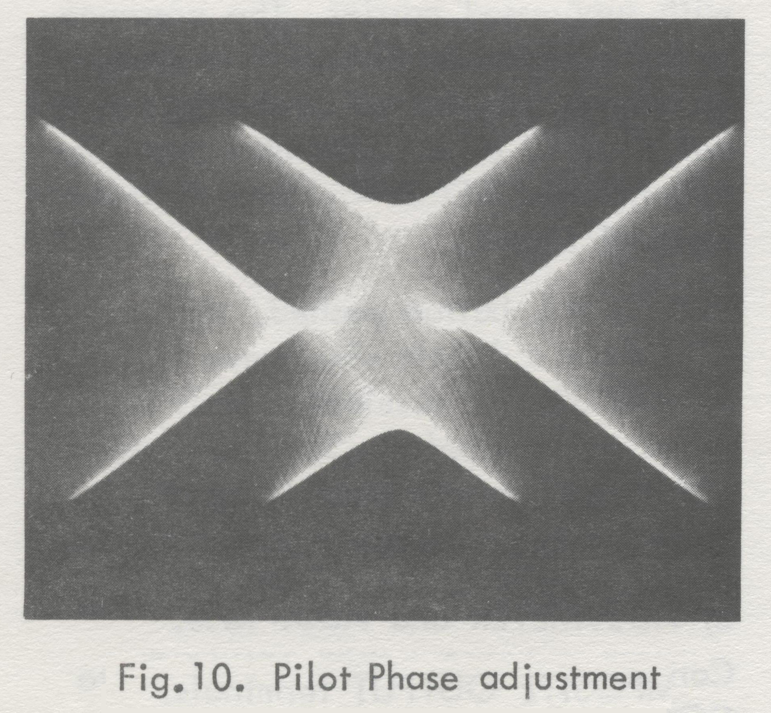 8) PILOT LEVEL
Push buttons MOD.OFF and PILOT.
Depress button METER.
Adjust the potentiometer R128, PILOT LEVEL (accessible from the front panel), until the meter reads 8-10% (marked on the 0-15% scale).
9) PILOT PHASE
Connect an oscilloscope to COMPOSITE OUTPUT terminals, and synchronize from MODULATION FREQUENCY SYNC. terminals.
Push buttons PILOT and INTERNAL MODULATION R = -L.
Push MODULATION FREQUENCY button 1 kHz. (If the modulation frequency by chance turns out to be a sub-harmonic of the pilot frequency, push both the 1 kHz and the 5 kHz (10 kHz for SMG1S2) buttons). Vertical as well as horizontal expansion will then produce a picture on the scope as seen in Fig. 10. Turn the inductance adjuster of the inductor L3, until the two arrow points are on the same horizontal line.
The following three items relate to the RF-UNIT. The RF-oscillator and the FM modulator are housed in a shielding box.
They are mounted on a small print board, which becomes accessible by removing four nuts and pulling away half of the box.
10) Output voltage
With all RF-LEVEL buttons out, set the output voltage to 100 millivolts by moving the loop coil L404 in relation to the tuning coil L403. Make sure that the output voltage is correct when the cover is replaced.
Check the RF-attenuator by measuring the output voltages when the RF-LEVEL buttons are pushed in different combinations.
11) Modulation linearity and peak-deviation.
Connect an FM modulation meter (deviation meter) to the RF-OUTPUT terminal and tune it to the frequency of the RF-Unit. Connect a distortion meter or a wave analyzer to the AF-output of the modulation meter.
Push buttons SET DEV. and MODULATION FREQUENCY 1 kHz.
The meter should now read 100%.
Note:
During the following adjustments, it is important that the RF-oscillator box is assembled. Adjust with an insulated screw-driver through the holes marked
ADJ.1 and ADJ.2.
Set the resistor R402 “MOD.BlAS”(ADJ.1) to minimum modulation distortion, measured on the distortion meter or the wave analyzer.
Set the resistor R405 “FM DEV.”(ADJ.2) to 75 kHz peak-deviation, measured on the modulation meter.
Repeat the adjustment of R402 and R405, until both potentiometers are in optimum position.
12) FREQ.ADJ. Fine-adjustment of the RF-frequency.
A fine-adjustment of the RF-frequency is made with the screw-driver adjustment FREQ.ADJ., accessible from the front panel.
The frequency change is so small that the accompanying peak-deviation change as a rule is insignificant.
If accurate peak-deviation is essential, make the adjustments outlined in 11).
DC Potentials
The potentials listed on the following pages can be used to locate faults.
The potentials are referred to ground and measured with a vacuum-tube voltmeter with a 2 MΩ probe to avoid capacitive loading.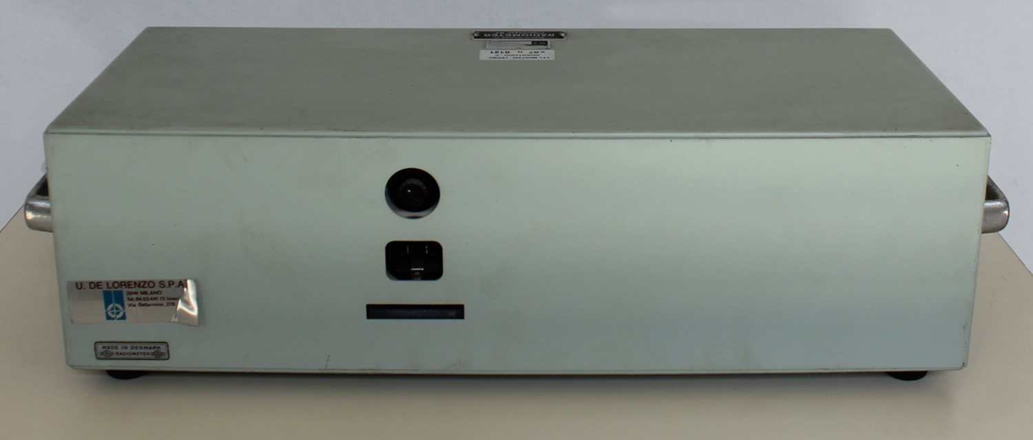 Section H. Applications
GENERAL
This chapter does not purport to provide a complete exposition on ways and means of testing and aligning a stereo multiplex receiver or adapter. The proper procedure will to a great extent depend on what the user wants to test and which auxiliary instruments are available. In the following are sketched some measurements which can be made with the Stereo Generator and some commonly used auxiliary instruments are mentioned. With this as a guide, the user should be able to plan the measuring procedure needed for his requirements.
For use in the greater part of the measurements mentioned below, the following instruments are to be recommended:
Wave Analyzer: Radiometer, FRA3
Audio Frequency VTVM: Radiometer, RV24
Distortion Meter: Radiometer, BKF6
Low Distortion Audio Oscillator: Radiometer, HO32
Oscilloscope (without phase- or amplitude distortion for the frequency range 50 Hz -53 kHz): Tektronix, 515
To avoid damage to your stereo generator, never apply voltages above 10 volts rms to the terminals.
INITIAL CONNECTIONS AND SETTINGS
(See also OPERATING INSTRUCTIONS).
In most cases internal modulation is adequate. Therefore, in the following, internal modulation will normally be assumed. It, however, external modulation is required, the measurements can be carried out in a similar way (see OPERATING INSTRUCTIONS).
Pre-emphasis can be used, if desired. When measuring on an adapter (or
tuner + IF amplifier + discriminator + adapter) without de-emphasis circuit (de-emphasis circuit being placed in the succeeding AF-amplifier), it is more convenient not to use pre-emphasis. In other cases it may prove more convenient to use pre-emphasis.
Note, however, that when using internal modulation and pre-emphasis, full driving signals (i.e. 100% meter deflection, 7 volts peak at COMPOSITE OUTPUT terminals with AMPLITUDE knob turned fully clockwise, and 75 kHz peak-deviation of the RF-signal) are obtained only for 5 kHz (10 kHz for SMG1S2) modulation frequency, while lower signals are obtained for 80 Hz and 1 kHz. Full driving signals include the pilot signal.
When using external modulation and pre-emphasis, the modulating voltage should be set either to a fixed value, giving full deflection for the highest modulation frequency to be used, or it should be reduced as the modulation frequency is increased, to avoid overdriving the Stereo Generator and thus exceeding the standard deviation.
It is assumed that the standardized pilot signal is to be used. Refer to OPERATING INSTRUCTIONS under “Special Operating Modes 2” for setting up a non-standard pilot amplitude or phase.
Some of the following measurements are not exclusively applicable to stereophonic investigations, but can also be used in work on monophonic FM receivers (or stereophonic receivers operated as monophonic receivers). In such cases, always push R = L (M) button (INTERNAL or EXTERNAL MODULATION), and release PILOT button. Except for this, proceed as described in the following.
The initial connections and settings depend on which output signal is to be used – i.e. the composite output for adapters or the RF-output for receivers.
Initial connections and settings for measurements on adapters
1) Connect the adapter to COMPOSITE OUTPUT terminals.
2) Push button PILOT.
3) Push the appropriate PRE-EMPHASIS button (European standard: 50 μsec, American standard: 75 μsec), if desired.
4) Push 1 kHz MODULATION FREQUENCY button.
5) Set AMPLITUDE KNOB to the level suitable for the adapter. This can be accomplished in several ways:
Push one of the INTERNAL MODULATION BUTTONS. With an oscilloscope connected across COMPOSITE OUTPUT terminals, the peak-to-peak value can be measured on the screen.
Using a normal rms-calibrated vacuum voltmeter, the signal used for setting the level must be a pure sine-wave. This can be obtained by pushing SET DEV. button.
A conventional VTVM (rms-calibrated, mean-value or rms-measuring) should be used only for purposes of comparing.
When the built-in meter reads 100% and AMPLITUDE control is turned fully clockwise, the peak-voltage on COMPOSITE OUTPUT terminals will be close to 7 volts. By now comparing the readings of a VTVM connected across COMPOSITE OUTPUT terminals, when AMPLITUDE knob is turned fully clockwise, with the readings when it is turned partly up, it is possible to calculate the peak output voltage for any AMPLITUDE setting.
The stereo generator is now ready for the measurements on adapters described in the following paragraphs.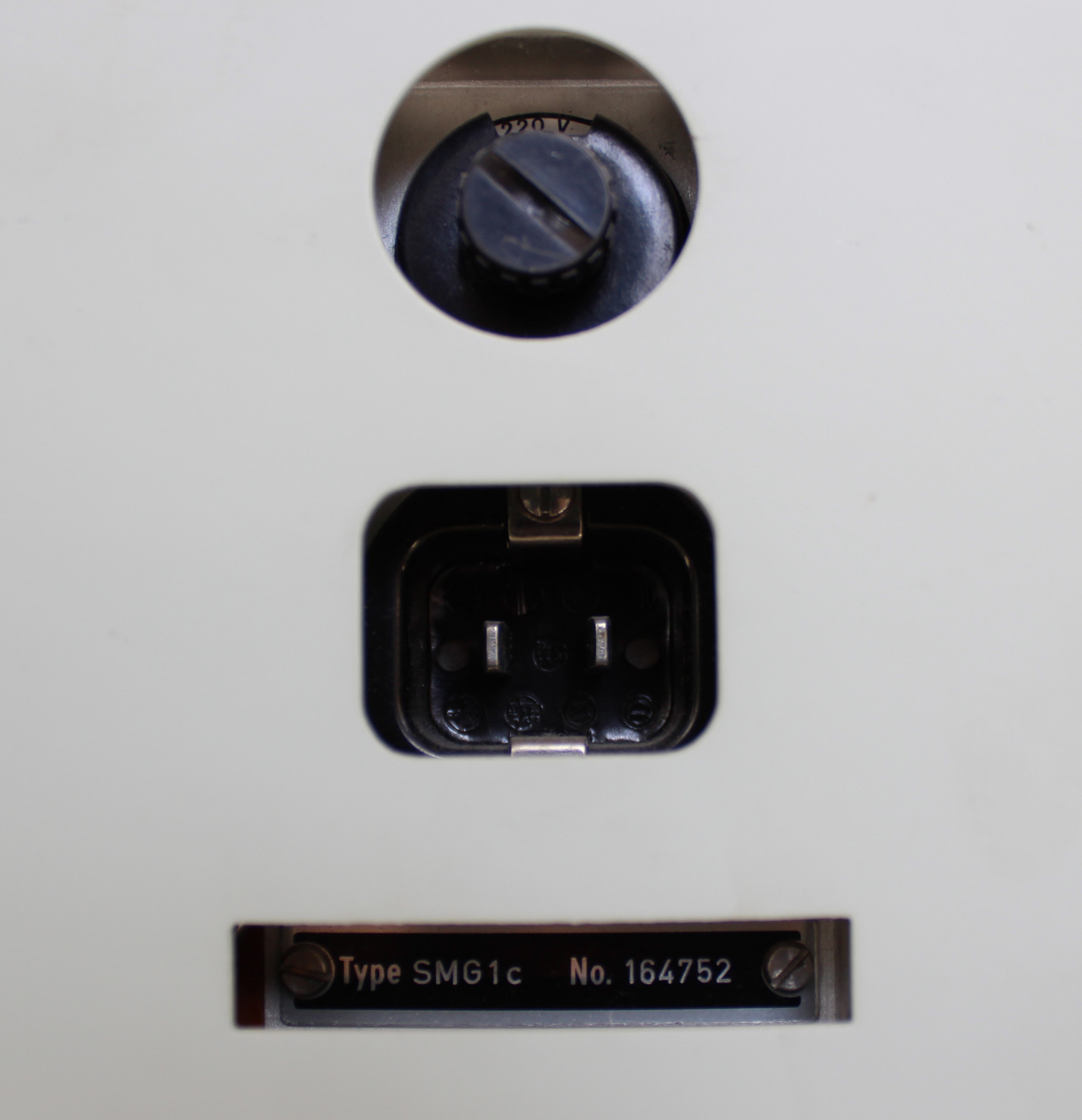 Initial connections and settings for measurements on receivers
1) Push the RF-oscillator switch (knob of the AMPLITUDE control).
2) Set RF-LEVEL to an appropriate value.
3) Push PILOT button.
4) Push appropriate PRE-EMPHASIS button (European standard: 50 μsec, American standard: 75 μsec), if desired.
5) Push 1 kHz MODULATION FREQUENCY button.
6) Connect RF-OUTPUT terminals to the antenna terminals of the receiver, and tune the receiver to the output frequency of the stereo generator (approx. 100 MHz)
The stereo generator is now ready for the measurements on receivers described in the following paragraphs.
LR SEPARATION (LR-SEPARATION IS EQUAL to MS-IDENTITY)
1) Push button L.
2) Measure the voltages at the left and right output terminals of the adapter or receiver. The ratio of these voltages is the L to R separation (L to R crosstalk).
3) Push button R.
4) Measure the voltages at the right and left output terminals of the adapter or receiver. The ratio of these voltages is the R to L separation (R to L crosstalk).
5) If desired, repeat the measurements for other modulation frequencies.
Note:
In case the output signal of the adapter or receiver contains hum, or 19 or 38 kHz residual signals, make sure that these signals do not compromise the measurements. Use a selective vacuum tube voltmeter (wave analyzer), appropriate filters in front of a VTVM, or an oscilloscope synchronized from the MODULATION FREQUENCY SYNC. LR BALANCE EXPRESSED BY MEANS OF THE IDENTITY FACTOR (LR-IDENTITY IS EQUAL TO MS-SEPARATION)
The identity factor is an expression of the differences in amplification of L- and R-channels.
Let the ratio of the amplification of L-channel to that of R-channel be denoted by “f”, then the Identity Factor is equal to
20 log10 (1+f)/(1-f) dB.
Measuring the Identity Factor
1) Connect the ungrounded side of the L and R output terminals of your adapter or receiver through two identical resistors in series. The value of the resistors must be high as compared with the output impedance of your adapter or receiver.
2) Press button R = L (M)
3) Measure the voltage between the point of junction of the two resistors and ground (V1) by means of a frequency analyzer (or a VTVM and a low-pass filter which removes any residual signals that may be present at 19 kHz and 38 kHz).
4) Press button R = -L (S).
5) Measure the resultant voltage (V2).
The LR identity factor can now be determined as
20 log V1/V2 dB.
FIDELITY
If a check of the fidelitypat the three built-in modulation frequencies is sufficient:
1) Push button L.
2) Measure the voltage on the left output terminals of the adapter or receiver for modulation frequencies 1 kHz, 80 Hz and 5 kHz. (80 Hz, 1 kHz or 10 kHz for SMG1S2.)
If the de-emphasis of the adapter or receiver agrees with the pre-emphasis of the Stereo Generator, the voltage will be the same for all three modulation frequencies, when the tone controls are in neutral position.
3) Repeat the measurement for the right channel by pushing R ONLY button and measuring on the right output terminals of the adapter or receiver.
If a detailed frequency response is to be measured:
1) Push L & R button (EXTERNAL MODULATION).
2) Connect an external audio signal generator to L INPUT terminals, and adjust its output voltage to full deflection on the meter for the highest modulation frequency to be used.
3) Measure the voltage on the left output terminals of the adapter or receiver as a function of frequency. If the de-emphasis of the adapter agrees with the pre-emphasis of the Stereo Generator, the voltage will be frequency-independent in the audio frequency range, when the tone controls are in neutral position.
4) Connect the audio signal generator to R INPUT terminals and repeat the measurement of the right channel.
Measuring the frequency response for the monophonic (M) channel and the stereophonic (S) sub-channel
1) Push button R = L (M) (INTERNAL or EXTERNAL MODULATION, as required).
2) Measure the voltage on the left or right output terminals of the adapter or receiver as a function of frequency.
3) Push button R = -L (S), and repeat the measurement.
DISTORTION
In most practical cases it is sufficient to check the distortion at a low, a medium and a high modulation frequency. The built-in modulating oscillator is designed with due regard to this particular application. Its distortion is very low, its low modulation frequency has been chosen so as not to interfere with the line frequency, and its high modulation frequency has been selected as the maximum frequency, whose second and third harmonics will pass through the AF amplifier of the receiver under test.
If other test-frequencies are required, a low-distortion, audio frequency signal generator should be used.
Measuring the distortion
1) Push one of the modulation buttons of FUNCTION SELECTOR, depending on the type of multiplex-signal for which the distortion is to be measured.
2) Measure the distortion with a wave analyzer or a distortion meter connected to that adapter – or receiver – output that corresponds to the type of multiplex-signal under measurement.
3) If desired, repeat the measurement for modulation frequencies of 80 Hz and 5 kHz, (10 kHz for SMG1S2), and for other types of multiplex-signals.
Note:
If a distortion meter is used, make sure that the measurements are not disturbed by 19 or 38 kHz spurious signals. If that is the case, insert a low-pass filter with a cut-off frequency of 15 kHz (and, perhaps, traps at 19 and 38 kHz) in front of the distortion meter.
MEASURING INTERMODULATION BETWEEN THE HARMONICS OF THE L OR R SIGNAL AND SIGNALS AT 19 kHz AND 38 kHz (THE PILOT SIGNAL AND THE REGENERATED CARRIER SIGNAL)
Components produced by intermodulation of this kind in the stereo generator are typically 90-100 dB below the level of the L or R signal.
Measuring intermodulation with an R or L signal frequency, fA:
1) Connect a low-distortion generator to the L or R input (the built-in modulation generator can be used, too).
2) Push button R & L.
3) Set the frequency of the signal generator to fA, and adjust the amplitude, so that the built-in meter reads 100%.
4) Measure the intermodulation components at the output of either channel by means of a frequency analyzer. The frequency of the intermodulation components will be
±n1 × fA ± n2 × 19 kHz,
where n1 and n2 are integers.
M AND S CHANNEL IDENTITY OF TUNER, IF AMPLIFIER AND DISCRIMINATOR IN A RECEIVER (MS- IDENTITY IS EQUAL TO LR -SEPARATION)
Measured with an oscilloscope
1) Connect an oscilloscope to the discriminator output. Make sure that the capacitive load gives a cut-off frequency that is larger than 500 kHz. Do not use a probe, as this will cause amplitude- and phase-distortion, it not adjusted very carefully.
Trigger the oscilloscope from MODULATION FREQUENCY SYNC. terminal.
Use an oscilloscope with a flat amplitude and a linear phase characteristic from 30 Hz to at least 75 kHz.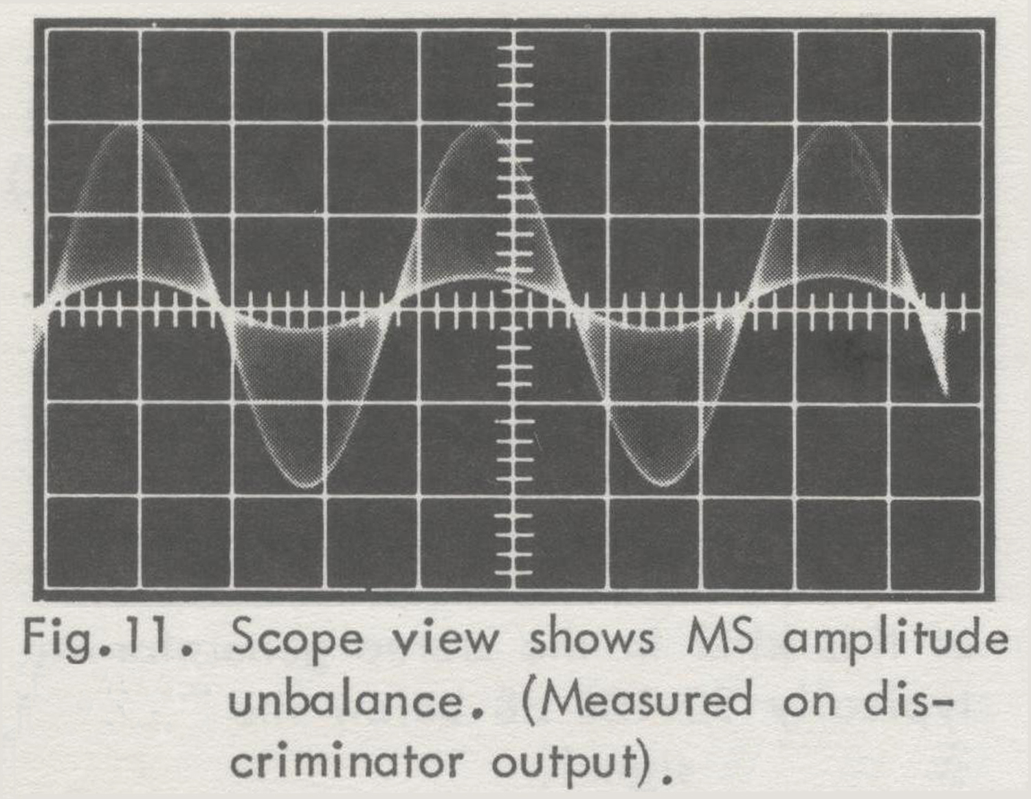
 2) Push L or R button.
3) Release PILOT button.
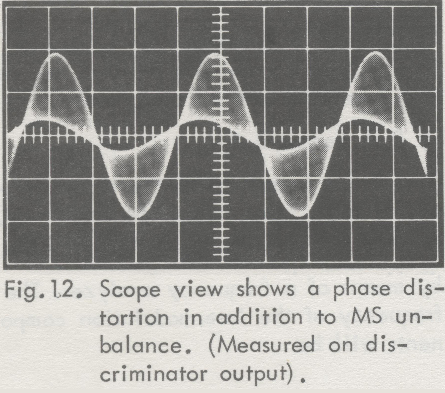
4) The scope will now show a picture as in Fig. 11 or 12.
Fig. 13 shows the ideal case with perfect M and S channel identity. In practice, however, scope views as in Fig. 11 and 12 will be obtained.
Fig. 11 shows MS amplitude unbalance (the S channel amplitude is too low).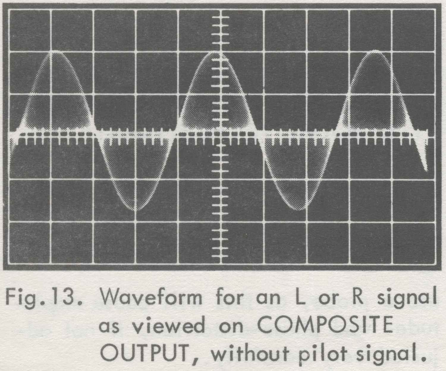
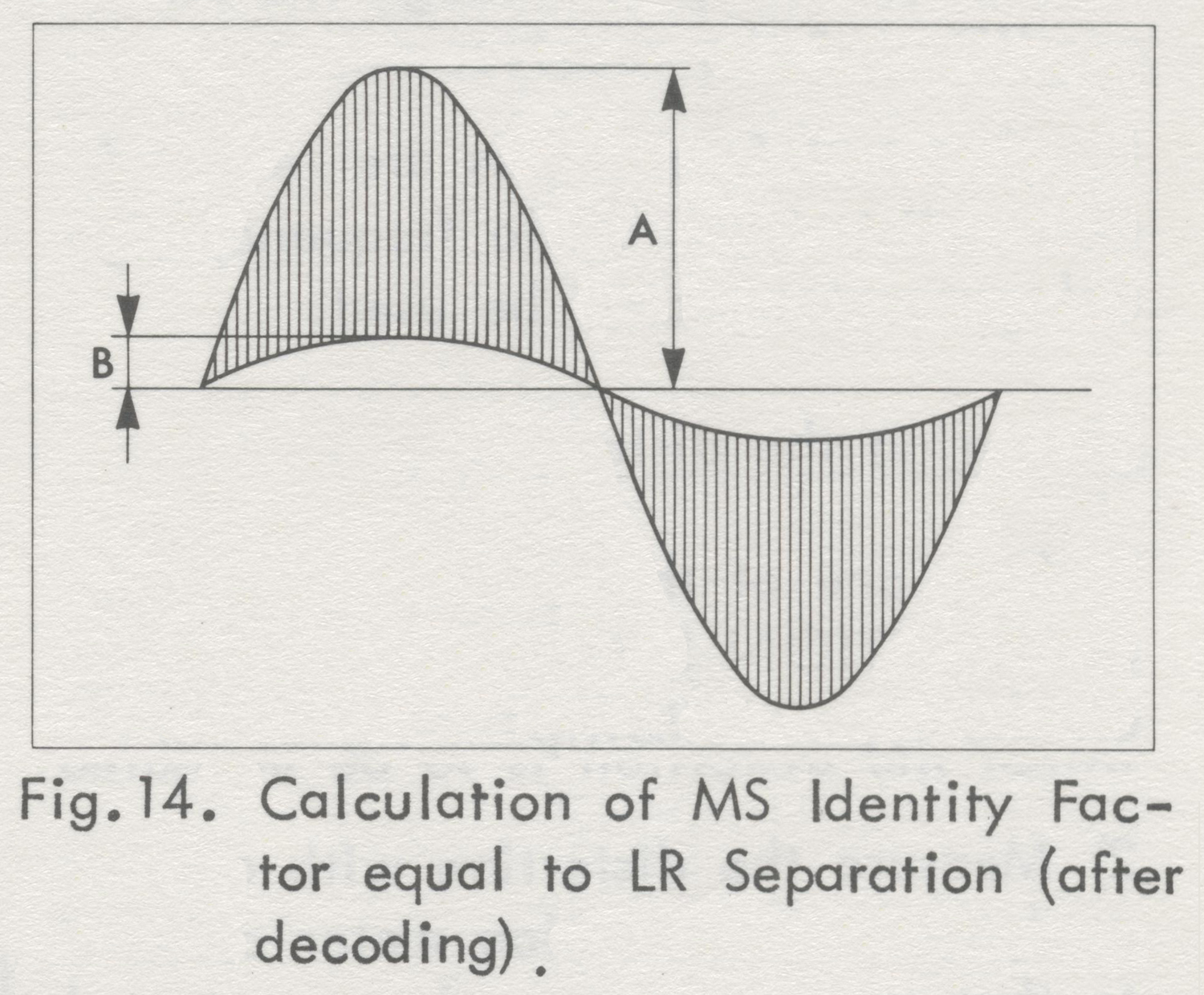 From this picture the MS Identity Factor equal to the LR Separation (after demodulation in an ideal multiplex decoder) can be calculated as shown in Fig. 14.
Fig. 12 shows a phase distortion in addition to MS amplitude unbalance (indicated by a non-coincidence of corresponding tops of the two sinusoidal envelopes).
5) Repeat the measurement for other modulation frequencies; if convenient, also for a very high frequency (10 to 15 kHz, using external modulation), where MS unbalance and especially phase distortion
often are very pronounced.
Measured with a wave analyzer (for frequencies up to 53 kHz)
(This method gives no information aboutphase distortion).
1) Connect a wave analyzer to the discriminator output. Make sure that the capacitive load gives a cut-off frequency that is larger than 500 kHz.
2) Push L or R button
3) Measure the discriminator output signal components at the modulation frequency (monophonic channel), and at 38 kHz plus and minus the modulation frequency (stereophonic sub-channel sidebands) .
For perfect MS identity the amplitude of the two sidebands should be equal, and either should be equal to half the amplitude of the monophonic channel signal.
If phase distortion is disregarded, the MS Identity Factor will be:
20 log10 (1+f)/(1-f) dB,
f = m/(s1 + s2)
where m is the monophonic channel signal voltage, and s1 and s2 are the voltages of the stereophonic sub-channel side-bands.
M AND S CHANNEL SEPARATION OF TUNER, IF AMPLIFIER AND DISCRIMINATOR OF A RECEIVER (MS-SEPARATION IS EQUAL TO LR-IDENTITY)
M to S Separation (Crosstalk)
1) Connect a wave analyzer (frequency range: 40 Hz to 53 kHz) to the discriminator output.
2) Push button R = – L (M)
3) Measure the discriminator output signal components at the modulation frequency (monophonic channel), and at 38 kHz plus and minus the modulation frequency (stereophonic sub-channel sidebands) .
The M to S separation is:
20 log10 m/(s1 + s2) dB,
where m is the monophonic channel signal voltage, and s and s are the voltages, and s1 and s2 are the voltages of the (unwanted) stereophonic sub-channel sidebands.
S to M Separation (Crosstalk)
1) Connect a wave analyzer (frequency range: 40 Hz to 53 kHz) to the discriminator output.
2) Push button R = -L (S).
3) Measure the discriminator output signal components at the modulation frequency (monophonic channel), and at 38 kHz plus and minus the modulation frequency (stereophonic sub-channel sidebands).
The S to M separation is:
20 log10 (s1 + s2)/m dB,
where m is the voltage of the (unwanted) monophonic channel signal, and s1 and s2 are the voltages of the stereophonic sub-channel sidebands.
PILOT RESERVE
A stereophonic FM-receiver should in all circumstances be able to function correctly, even if the pilot sub-carrier were to depart from its normal level.
A deviation from the optimal value of amplification in tuners, etc., may very likely be caused by aging.
Measuring Pilot Reserve
1) Push button L (the R-channel could be used as well).
2) Reduce the level of the pilot signal until minimum allowable L to R separation, or maximum allowable distortion of the L channel, is reached.
Measuring the separation and measuring the distortion are described above.
The level of the pilot signal is changed by turning screwdriver adjustment LEVEL below button PILOT.
3) Push button MOD. OFF.
4) Read the level of the pilot signal on the meter. Press button METER to get an accurate reading.
5) Push button L.
6) Increase the level of the pilot signal until minimum allowable L to R separation or maximum allowable distortion is reached. However, the pilot signal should not exceed the level corresponding to 20% modulation.
7) Push button MOD. OFF.
8) Read the level of the pilot signal on the meter.
9) The readings in (4) and (8) give the allowable range of the pilot signal amplitude.
Note:
The measurements at increased pilot signal level assume that the FM- receiver has a bandwidth large enough not to cause distortion for a 10% increase of the frequency deviation.
MEASURING FM DISCRIMINATOR CHARACTERISTICS
In multiplex stereo development work it often may be necessary to measure the harmonic distortion of the FM discriminator versus the modulation frequency. The modulation frequency range is 40 Hz to 53 kHz. If an FM signal generator capable of handling this modulation frequency range is not available, the Stereo Generator can be used.
See OPERATING INSTRUCTIONS for further instructions.
For the distortion measurements use a wave analyzer, accepting high frequencies (up to third harmonic of the highest modulation frequency), or use a VLF receiver (20 – 200 kHz) or appropriate filters together with a wide-band VTVM.
LISTENING TESTS
1) Connect a gramophone or tape recorder to the AUDIO INPUT.
2) Push buttons AUDIO, PILOT and PRE-EMPHASIS (European Standard: 50 µsec, American Standard: 75 µsec).
3) Turn SENSITIVITY knob, so that the meter reads 50-70% during loud passages in the music.
Note:
During interruptions or soft passages in the sound, the tone of the built-in oscillator may be heard. To eliminate this tone, the oscillations of the built-in oscillator should be stopped by releasing all three frequency buttons of the oscillator. All three buttons are released by gently pushing one of the buttons just so far that the other two buttons are released, and then letting go of the button».
§§§
Per consultare la prima parte scrivere ”SGM1” su Cerca.
Foto di Claudio Profumieri; elaborazioni, ricerche e testo a cura di Fabio Panfili.