
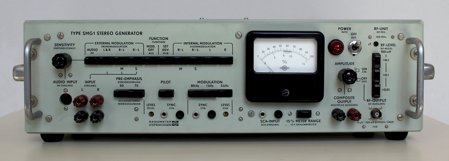
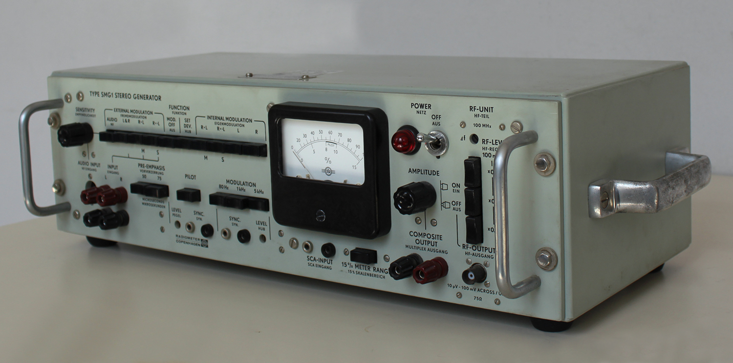
 Type SMG1 Stereo Generator Radiometer Copenhagen No. 164752. Prima parte.
Per ingrandire le immagini cliccare su di esse col tasto destro del mouse e scegliere tra le opzioni.
Mentre scriviamo queste note non disponiamo dell’inventario dell’epoca nel quale lo strumento si trova al n° D 4932.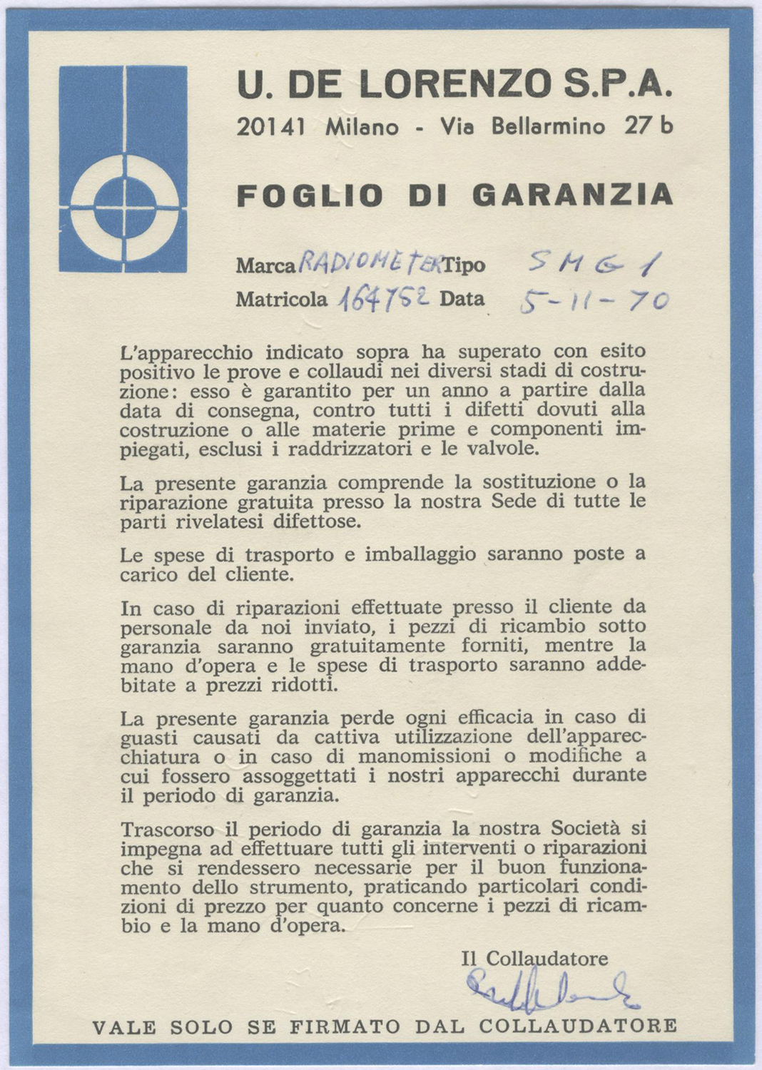 Dal foglio di garanzia risulta la data di acquisto: 5 novembre 1970. Inoltre vi si legge che l’importatore è U. De Lorenzo s.p.a. – Milano.
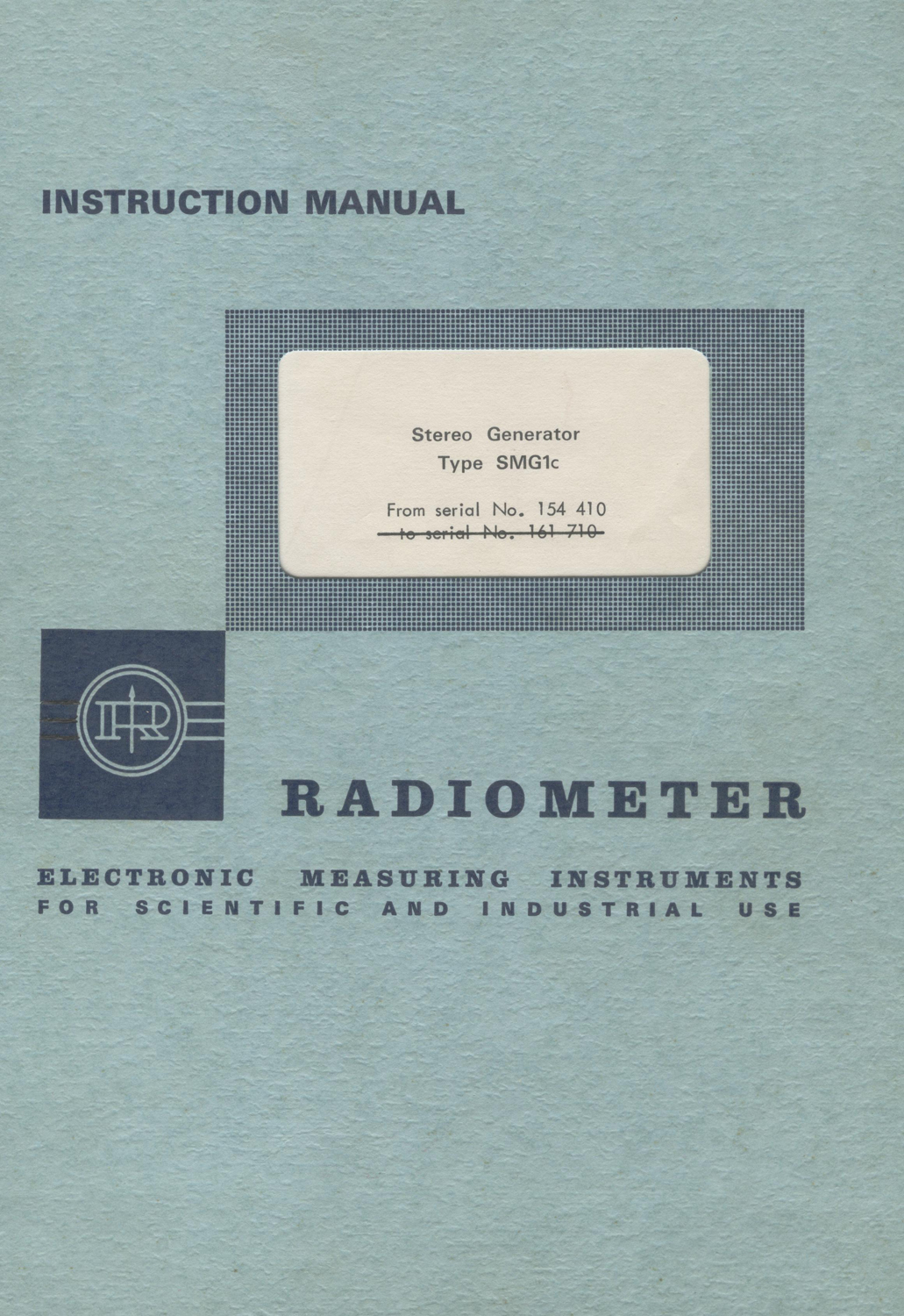
Nella Sezione Elettronica è custodito il manuale di istruzioni della ditta, del quale riportiamo alcune parti.
§§§
«Stereo Generator Type SMG1
Section A. Introduction
PRINCIPLES FOR GENERATING A MULTIPLEX STEREO-SIGNAL ACCORDING TO THE FCC SYSTEM
The frequency spectrum for a multiplex Stereo-signal of the approved FCC system is shown in Fig.1.
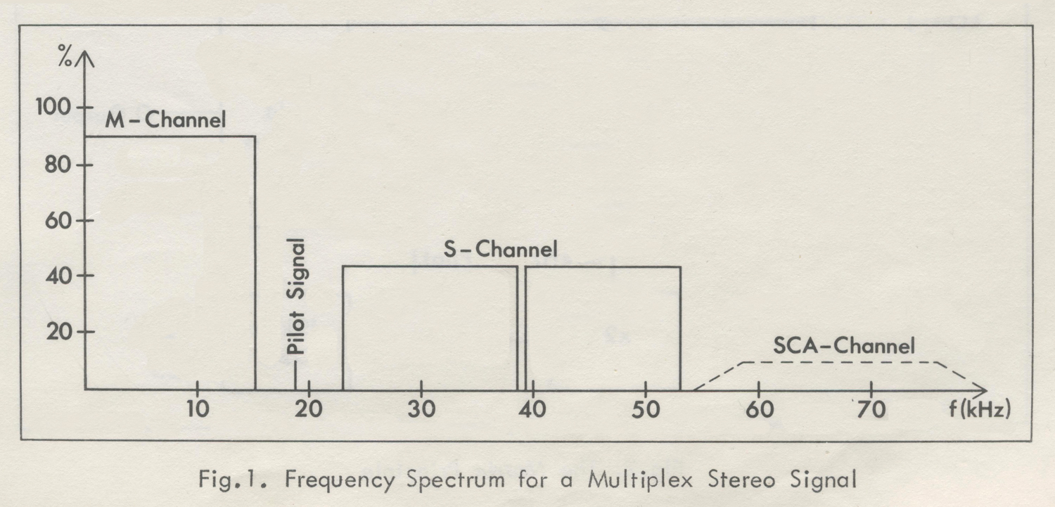
The M-channel (Main or Monophonic Channel) occupies the frequency range 50 Hz to 15 kHz. The M-signal is made up of the sum of the left and right signals (L + R). This enables a stereophonic broadcasting station to be received on a monophonic receiver (compatibility).
The difference between the left and right signals (L – R) is transmitted as a double sideband signal, amplitude-modulated on a suppressed sub-carrier of 38 kHz (S-channel or stereophonic sub-channel, covering the frequency range 23 – 53 kHz).
In the receiver, the difference signal (L – R) is obtained by regenerating the 38 kHz carrier and demodulating the S-channel.
However, this carrier must be in exact phase with the suppressed 38 kHz carrier on the transmitter side, and to accomplish this, a pilot signal of 19 kHz (half of the suppressed carrier frequency) is transmitted with a normalized amplitude and with a stated phase relationship to the suppressed carrier.
The FCC allows a third channel, the SCA-channel (Subsidiary Communications Authorization) to be transmitted as a frequency-modulated sub-carrier on 67 kHz. This channel is used for background music in department stores, etc. It must not occupy more than 10% of the maximum peak- deviation of the FM broadcast transmitter.
The multiplex stereo signal can be generated in the two ways described in the following:
Fig.2 shows the Matrix Principle. In a matrix circuit the sum (L+ R) and the difference (L – R) of the left (L) and right (R) signals are obtained. The sum- signal is passed onwards to an adder network, and the difference-signal is modulated into a 38 kHz carrier. Using a balanced modulator, the carrier is suppressed, so that the modulating process results in two sidebands, which pass on to the adder network.
The 38 kHz carrier is obtained by frequency-doubling a 19 kHz signal from a crystal-controlled oscillator. The 19 kHz signal is also fed to the adder network as a pilot signal.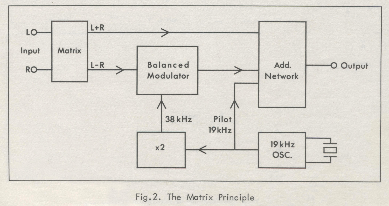 The output signal from the adder network is the composite multiplex stereo-signal, which is used to frequency-modulate the transmitter.
Fig.3 shows the Time-Multiplex or Time- Division Principle. Here an electronic switch alternates between the left (L) and right (R) signal at a frequency of 38 kHz.
The 38 kHz carrier and the 19 kHz pilot signal are formed in the same way as in the Matrix Principle.
By the switching process, sidebands to the odd harmonics of the carrier frequency will be produced. They are, however, eliminated by a filter with a 53 kHz cut-off frequency.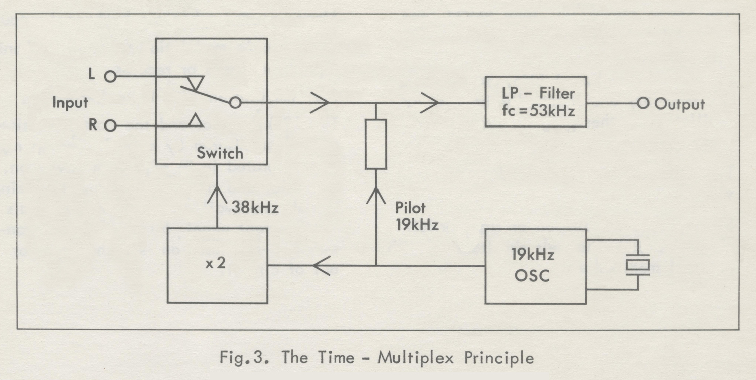 Mathematically it can be proved that the output-signal from the filter has the frequency spectrum shown in Fig.1, except that some unbalance between the main-channel and the stereophonic sub-channel is present. This unbalance would result in LR cross-talk after decoding; however,
the unbalance can be compensated for either in the switching modulator or in the filter.
THE STEREO GENERATOR, TYPE SMG1
In the Stereo Generator, type SMG1, the time-multiplex principle has been adopted, because of its obvious advantages, of which one of the most significant is the completely uniform handling of the left and right signals, which implies that minor amplitude – and phase – differences become less probable.
The Stereo Generator, type SMGT, is a transistorized, line-operated instrument that complies with the standards for stereophonic broadcasting approved by the American FCC and recommended by the
European Broadcasting Union (EBU).
The composite signal may be used testing stereo adapters or driving FM
generators to a full 75 kHz deviation.
A built-in 100 MHz oscillator, frequency-modulated by the composite
signal and provided with a step attenuator, makes the instrument self-contained by generating an FM multiplex signal for tests on receivers and tuners.
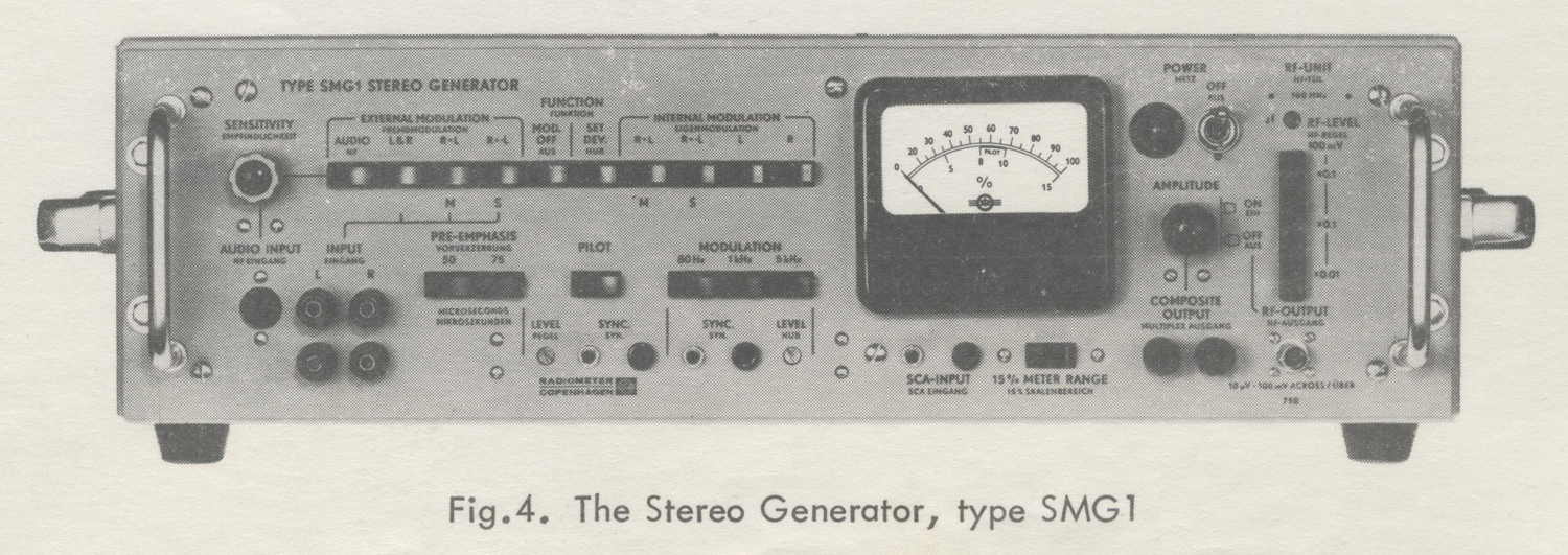
The Stereo Generator, type SMG1, can be modulated internally by a built-in oscillator with choice of 80 Hz, 1 kHz, and 5 kHz (80 Hz, 1 kHz, and 10 kHz for SMG1S2) and externally from an AF oscillator or other program source.
The following operating modes are provided:
Stereophonic modulation of right or left channels. Both channels simultaneous with external modulation.
Mono-or stereophonic sub-channel output.
Stereophonic modulation with stereophonic input from tapes or records.
SCA modulation with FM sub-carriers.
The 19 kHz pilot and the composite signal are monitored by a peak-reading meter calibrated in % of system deviation.
The pilot and the oscillator synchronizing signals are available from two terminals on the front panel. 50 and 75 μsec. standard pre-emphases are switchable in or out of circuit.
Section B. Specifications
INPUTS
Left (L) and Right (R) Inputs
Frequency range: 40 Hz to 15 kHz.
Fidelity: ±0.2 dB.
Input Voltage: Approx. 250 millivolts rms for 100% modulation (inclusive of 10% pilot signal). Maximum input voltage is 10 volts.
Input Impedance: 10 to 15 KΩ depending on FUNCTION SELECTOR setting.
Audio Input (Provides for stereo inputs from tapes and records. An input filter suppresses 19 kHz spurious signals).
Frequency Range: 40 Hz to 15 kHz,
Fidelity: Approx. ±1 dB up to 12 kHz.
Input Voltage: Approx. 250 millivolts to 10 volts rms for 100% modulation (inclusive of 10% pilot signal), depending on SENSITIVITY setting.
Input Impedance: Approx. 15 kΩ .
SCA Input (Subsidiary Communications Authorization.
Frequency Range: 10 to 75 kHz,
Fidelity: ±0.5 dB.
Input Voltage: Approx. 250 millivolts rms for 10% modulation.
Input Impedance: 22 kΩ .
MODULATING OSCILLATOR
Frequencies 80 Hz, 1 kHz and 5 kHz.
Accuracy ± 5%,
Distortion Less than 0.1%.
PRE-EMPHASIS Standard 50 μsec pre-emphasis ± 1 dB.
Standard 75 μsec pre-emphasis ± 2 dB.
Switchable in or out of circuit.
OPERATING MODES
External Modulation
AUDIO Provides for stereo inputs from tapes and records tor listening tests.
L & R Normal two-channel multiplex signal output (also left only or right only signals).
R = L Monophonic channel output.
R = -L Stereophonic sub-channel output.
Internal Modulation
R = L Monophonic channel output.
R = -L Stereophonic sub-channel output.
L Left channel multiplex signal output.
R Right channel multiplex signal output.
Modulation OFF No modulating signal supplied, only 19 kHz
pilot supplied by pressing PILOT push-button.Set Deviation Pure sine-wave output supplied from COMPOSITE OUTPUT for setting deviation of external RF FM signal generator, it used.
OUTPUTS
Composite Output
Level: 0 to 7 volts peak.
Load Impedance: Minimum 1500 Ω shunted by maximum 300 pF
Overdrive Limit: Approx. 10 volts peak for load impedances greater than 10 kΩ.
Output Impedance: 40 to 250 Ω, depending on AMPLITUDE setting.
Distortion: Less than 0.2%.
Residual Hum and Noise: Less than 0.03%.
Residual 38 kHz Carrier: less than 1%, typically 0.5%.
Residual Spurious Signals above 53 kHz: Approx. 1%.
Pilot Signal: Switchable in and out.
Pilot Frequency: 19 kHz ± 2 Hz,
Pilot Level: Adjustable from 0 to 20%.
LR Separation: Better than 40 dB. Typically 45 dB modulation frequencies below 10 kHz.
MS Separation:
(Except AUDIO INPUT)
Pre-emphasis out: better than 45 dB.
Pre-emphasis in: better than 40 dB.
Modulating Oscillator Sync. Output
Frequencies: 80 Hz, 1 kHz and 5 kHz. (80 Hz, 1 kHz and 10 kHz for SMG1S2).
Level: Approx. 2 volts rms.
Source Impedance: Approx. 22 kΩ.
Pilot Sync. Output
Frequency: 19 kHz.
Level: Approx. 0.4 volts rms.
Source Impedance: Approx. 22 kΩ.
RF FM Output
Frequency: 100 MHz, adjustable within ± 0.5 MHz.
Output Voltage: 10 μvolts to 100 millivolts across a 75 Ω load. The voltage is adjustable in steps of 20 dB by means of a 20 + 20 + 40 dB attenuator.
Accuracy of output Voltage: from 100 μvolts to 100 millivolts: ±2 dB. At 10 μvolts: ± 6 dB.
Peak Deviation: ±75 kHz for 100% deflection on meter.
Accuracy of Deviation: ±5% at ± 75 kHz deviation.
Nominal Output Impedance: 75 Ω (60 Ω for SMG1S4), unbalanced.
VSWR: 1.2 to 1.6.
Distortion: Less than 1% at 75 kHz deviation, typically 0.5%.
LR Separation: Better than 40 dB. Typically 45 dB for modulation
frequencies below 10 kHz.
MS Separation: Pre-emphasis out: better than 45 dB.
Pre-emphasis in: better than 40 dB.
METER
Ranges 0 to 100% with peak value indication.
0 to 15% for pilot only.
Accuracy ± 3% of full scale deflection.
TERMINALS
L and R Input and Composite Output Binding posts that accept 4 mm banana plugs.
Spacing 19 mm (3/4″).
SCA Input, Pilot Sync. and Modulating Oscillator Sync. Standard 4 mm banana jacks.
Audio Input 5-pole sockets, type Preh 8-7505 (5 DIN 41524 M).
RF – Output Coaxial BNC socket, type UG-290/U.
POWER SUPPLY
Voltages: 110, 115, 127, 200, 220 or 240 volts.
Line Frequencies: 50 to 60 Hz.
Consumption: 11 watts,
SEMICONDUCTORS COMPLEMENT 26 transistors and 10 diodes.
MOUNTING AND FINISH Steel cabinet finished in grey enamel.
DIMENSIONS AND WEIGHT
Height: 160 mm (6 ¼ inches).
Width: 565 mm (22 ½inches)
Depth: 235 mm (9 ¼ inches).
Weight: 9.1 kilos net (20 lbs.).
ACCESSORIES SUPPLIED 1 Coaxial Cable (75 Ω), type 6D6, with
BNC plugs, type UG-88/U.
1 Power Cord, type 12G19-1.5.
1 Plug, type Preh 8-7506, for Audio Input.
ACCESSORIES AVAILABLE 20 dB Pad, type FDL2, 75 Ω
(Small 20 dB attenuator terminated in male and female type BNC connectors).
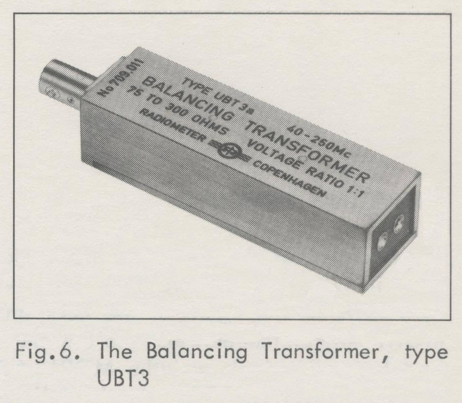
Balancing Transformer, type UBT3
(Provides for balanced output voltages from 40 MHZ to 250 MHZ. Impedance Ratio 75 to 300 Ω. Voltage ratio 1 to 1. Input socket
BNC type UG-290/U).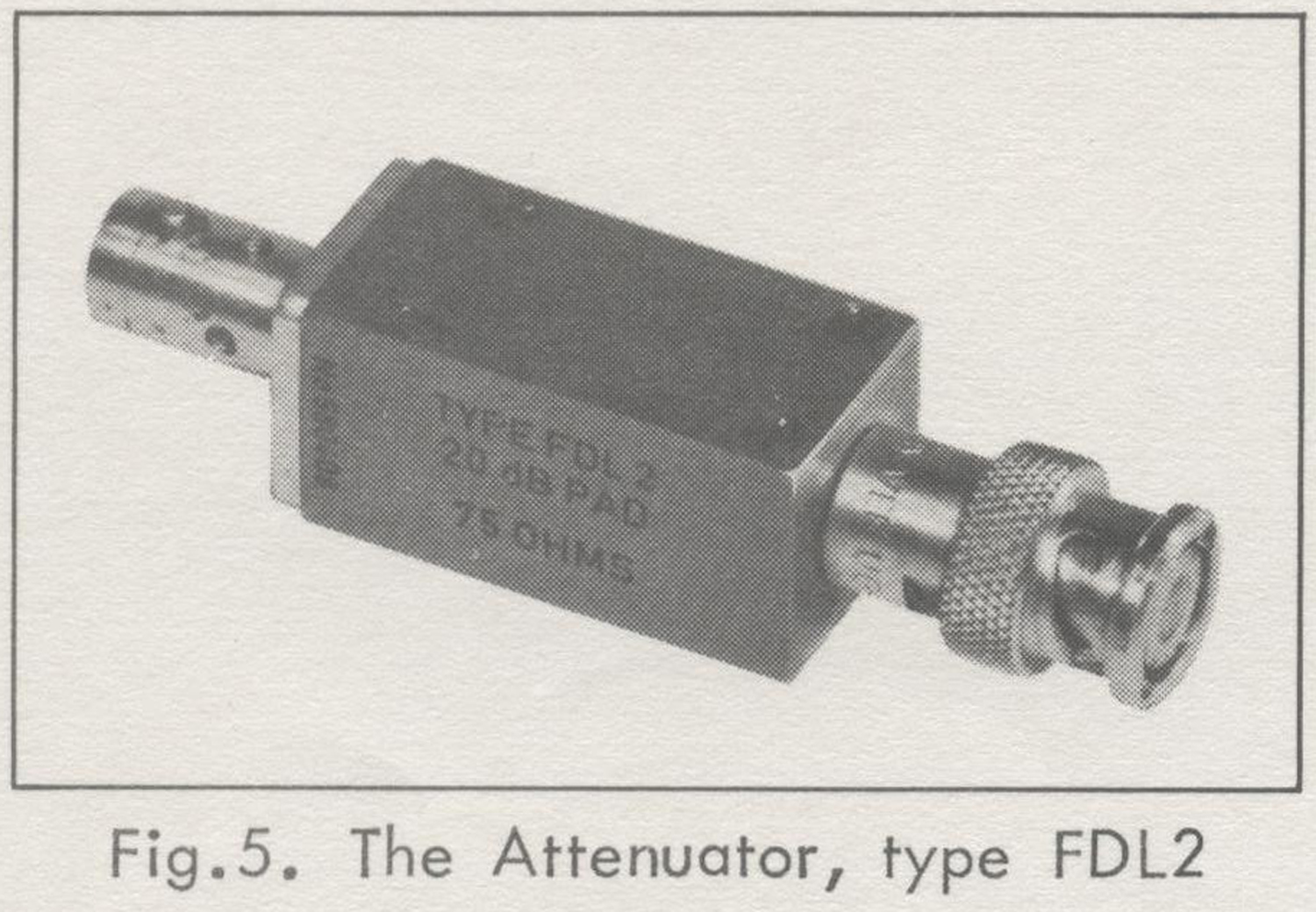 Section C. Accessories
General
The Attenuator, type FDL2, is an attenuator to be used from dc to about 300 MHz, with 75 Ω nominal impedance.
The attenuator is constructed as a single-section pi-type resistive network. It contains high-stability carbon resistors of the film-type, selected to close tolerances.
The attenuator is completely shielded by a metal casing; no undesired electrical coupling to the internal elements is possible.
Specifications
Attenuation: 20 dB
Impedance: 75 Ω
Accuracy: Within ± 0.2 dB at dc.
Within ± 0.5 dB to 250 MHZ.
Maximum Power
Input: 0.1 watt.
Dimensions:
Height: 18 mm (¾inch)
Width: 18 mm (¾inch)
Depth: 76 mm (3 inches)
Weight: 70 grams (2 ½ oz.)
Terminals:
BNC-type coaxial connectors, male and female.
BALANCING TRANSFORMER, TYPE UBT3
General
The Balancing Transformer, type UBT3, has been designed to produce a balanced output voltage from a signal generator.
It has a voltage ratio of 1:1 ; i.e. the calibration of the signal generator can be used directly.
When the Balancing Transformer is connected to a 75 Ω source the output impedance is 300 Ω. The balance of the output voltage is within a few per cent up to 200 MHz and within 5% to 250 MHz.
The unit contains a specially designed transformer and a resistive matching network. It has a BNC input socket and output from a socket which matches a commercially available 2-pin plug for twin-lead cable. One plug is supplied with the type UBT3.
Specifications
Frequency Response:
Within 1 dB from 40 MHz to 250 MHz with 300 Ω load.
Voltage Ratio: 1:1 ,
Accuracy of Output Voltage:
Within ± 1 dB of nominal value.
Output Impedance:
300 Ω when connected to a 75 Ω source.
Terminals:
Input: BNC socket, type UG290/U.
Output: Socket for 2-pin plug. The correct pin diameter is 3.2 mm (⅛ inch) and the spacing is 7.9 mm (5/16 inch).
Dimensions:
Height: 25 mm (1 inch)
Width: 18 mm (¾ inch)
Depth: 100 mm (4 inches)
Weight: 150 grams (5 ½ oz.)
Section D. General Description
OPERATING PRINCIPLE
In principle, as shown on the block diagram in Fig.7, the FUNCTION SELECTOR switches the inputs of the LEFT and RIGHT AMPLIFIER between the external modulation terminals and the MODULATING OSCILLATOR to obtain the following operating modes:
External Modulation
AUDIO:
Left and right amplifier connected to AUDIO INPUT.
Stereophonic music from tapes and records
L & R:
Left amplifier connected to L INPUT and right amplifier to R INPUT.
Normal two-channel multiplex output signal.
R = L:
Both amplifiers parallel-connected to L
INPUT.
Monophonic or Main-Channel output signal.
R = -L:
Left amplifier connected to L INPUT.
Right amplifier input signal a fraction (equal to the reciprocal amplification) of the left amplifier output voltage. Both amplifiers giving a 180 degrees’ phase shift, the output voltages of the left and right amplifier will be equal, but in opposite phase.
Stereophonic sub-channel output signal.
MOD . OFF:
Modulating circuits disconnected.
SET. DEV.:
The modulating oscillator connected directly to the output amplifier.
Internal Modulation
R = L:
Both amplifiers parallel-connected to the modulating oscillator.
Monophonic or Main-Channel output signal.
R = -L:
Left amplifier connected to the modulating oscillator. Right amplifier input signal a fraction of the left amplifier output voltage.
Stereophonic sub-channel output.
L
Left amplifier connected to the modulating oscillator.
Left channel multiplex signal output.
Right amplifier connected to the modulating oscillator.
Right channel multiplex signal output.
The switch modulator alternates between the left and right amplifier outputs at a frequency of 38 kHz. The switching voltage is a 38 kHz square wave signal obtained from a flip-flop. This flip-flop is triggered by a crystal-controlled 76 kHz oscillator and feeds another flip-flop, which divides the frequency into 19 kHz (square wave). A filter smoothens this signal into a sine wave, which serves as the pilot signal and is added to the output of the switch modulator.
The switch output signal and the pilot signal pass through a phase-linear low-pass filter to the output amplifier. The amplified signal is then measured with a peak-reading meter and fed to the RF-UNIT and to the Composite Output terminals via a potentiometer. The RF-UNIT is a frequency-modulated oscillator operating on 100 MHz and is modulated by the composite output signal from the output amplifier. Before the RF signal reaches the RF-OUTPUT terminal it may be attenuated as much as 80 dB in steps of 20 dB. CONTROL, METER and TERMINALS.
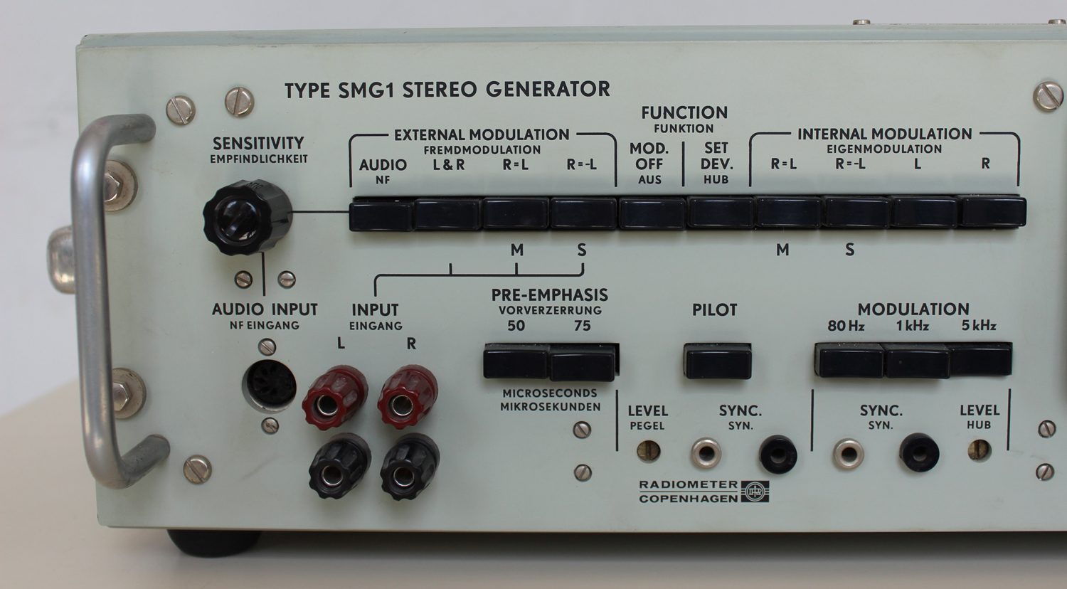
As can be seen on Fig. 8, all controls are located on the front panel.
(1) Power Switch and Pilot Lamp
Located near the upper right-hand corner of the meter.
Pilot lamp: Neon, 220 volts.
(2) FUNCTION SELECTOR
Selects the wanted operating mode as explained above.
(3) SENSITIVITY and AUDIO INPUT socket
The knob controls the modulation level, when an external modulation source (gramophone or tape recorder) is connected to the AUDIO INPUT five-pole socket.
(4) PRE-EMPHASIS
With both push-buttons out, the audio frequency response is straight from 40 Hz to 15 kHz (no pre-emphasis). With one of the buttons pushed in, the pre-emphasis is 50 μsec (European standard) or 75 μsec (American standard) respectively.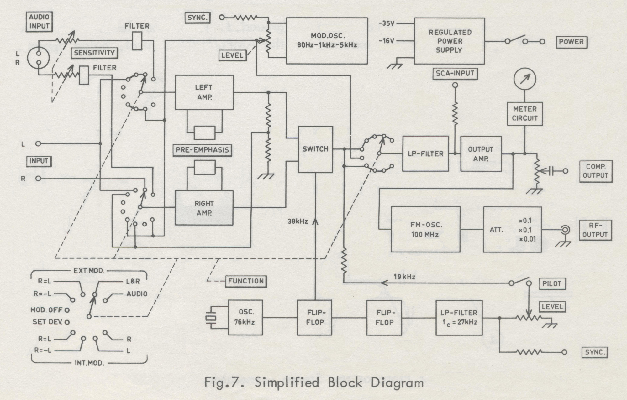 (5) PILOT, pilot LEVEL and SYNC.
Pushing the pilot button switches on the 19 kHz pilot signal. The level is set with the screw-driver adjustment marked LEVEL and can be indicated on the meter (see under METER). The pilot signal is available at the SYNC. banana-plug-type terminals for synchronization purposes
(approx. 0.4 volts rms), both with the button in and out.
(6) MODULATION FREQUENCY, LEVEL and SYNC.
Selects the desired modulation frequency when internal modulation is used. The screw-driver adjustment marked LEVEL sets the modulation level for internal modulation (see under METER).
The modulation signal is available from the SYNC. banana-plug-type terminals (approx. 2 volts rms).
(7) L and R INPUT terminals
When other than the built-in modulation frequencies are required, or when different left and right signals are wanted, external audio signal generators have to be connected to the left (L) and right (R) INPUT banana-plug-type terminals. The lower binding posts are grounded.
(8) METER and METER switch
The meter indicates the peak value of the composite signal. Normally, the upper scale, graduated from 0-100% of the system deviation, is used. By pressing the METER push-button below the meter, the range is changed to 0-15%. This range is mainly intended for setting the pilot signal level (normalized level being 8-10%). If, however, it is used to measure a complex signal – when a weak modulation signal is applied – the accuracy is approx. 5% only.
(9) SCA-INPUT terminals
To these banana-plug-type terminals an SCA (Subsidiary Communications Authorization) signal generator can be connected
(10) COMPOSITE OUTPUT and AMPLITUDE control.
The composite signal is available at the two binding posts marked COMPOSITE OUTPUT, of which the left one is grounded. The output level is set with the AMPLITUDE control, being approx. 7 volts peak when the control is turned fully clockwise, and the meter reads 100%
(11) RF-LEVEL and RF-OUTPUT terminal and RF-oscillator switch
A 100 MHz signal modulated with the signal on the COMPOSITE OUTPUT terminal is available on the BNC connector RF-OUTPUT. By means of the RF-LEVEL push-button switch, the level of the FM- signal can be changed from 100 mV to 10 μV in steps of 20 dB.
The peak-deviation is 75 kHz when the meter reads 100%.
The RF-oscillator can be switched off by pulling the knob of the AMPLITUDE control.
(12) Δf
To avoid interference from a local broadcasting station operating on a frequency close to 100 MHz, the carrier frequency of the FM-signal can be changed approximately ± 0.5 MHz with this screw-drive adjustment.
Line Voltage Receptacle, Fuse, and Voltage Selector
Are all located on the rear of the cabinet.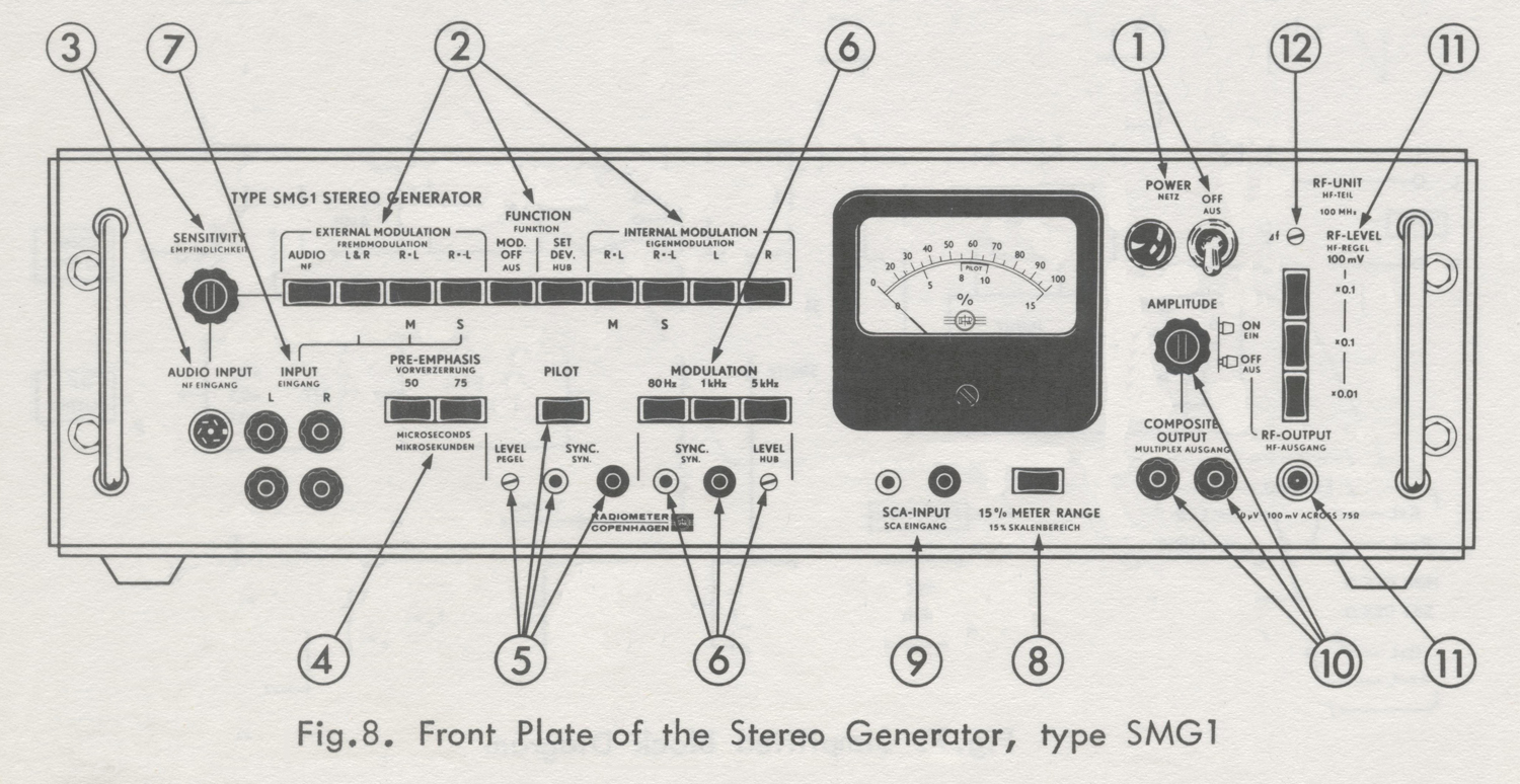 Section E. Operating Instructions
CONNECTION
Power
Before connecting the instrument to the power line, make sure that the line voltage selector is set to the voltage of the power line. The voltage selector is always set to 220 volts when the instrument leaves the factory.
To change to another voltage, loosen the centre screw on the voltage selector, and set the selector to the desired voltage.
The selector is accessible from the back of the cabinet. If the voltage is changed, it may also be necessary to exchange the fuse located in the selector.
The fuse type should be 80 mA, slow-blow, for 200, 220 and 240 volts, and 160 mA, slow-blow, for 110, 115 and 127 volts.
The generator is ready for use a few seconds after being connected to the power line. The first time some of the push-buttons are operated after connecting up, the meter-pointer will jump to full deflection, because the electrolytic capacitors are being charged. However, this will not damage the instrument.
External Modulating Sources
Gramophone or Tape Recorder.
The gramophone or tape recorder should be provided with amplifiers able to give at least 350 millivolts peak. The amplifiers should give the de-emphasis required for the employed playback system.
A plug, type Preh 8-7506, or the like should be used to connect the gramophone or tape recorder to the AUDIO INPUT.
The order of the connections, which complies with the DIN 41524 recommendations, appears from the circuit diagram appended to this manual.
The B & O types 610 VF, 41 VF and 42 VF stereo gramophones with built-in amplifiers can be used direct (Manufacturer: Bang and Olufsen, Struer, Denmark).
External Audio Signal Generators.
External modulation sources used for measurements should always be connected to the L and R terminals (binding posts).
Normally, unshielded leads will suffice, but in case of hum, shielded cables should be used.
When an M (R = L) output signal or an S (R = -L) output signal is wanted, the audio signal generator must be connected to the L-terminal. In other cases, the generator is connected to the L- or R- terminal, as required.
If different left and right signals are wanted, use either two external generators connected to the L and R terminals, or connect the L terminal to an external audio generator, and the R terminal (or vice versa) to the MODULATION FREQUENCY SYNC. terminal with a variable resistor shunting the terminals to ground.
Then choose the R signal modulation frequency with the MODULATION FREQUENCY switch, and set the level with the variable resistor.
SCA Sub-Carrier.
To add a normalized SCA sub-channel signal to the composite stereo signal, a frequency-modulated oscillator should be connected to the SCA INPUT terminals.
The carrier frequency should be approx. 67 kHz, the peak-deviation 7 kHz, and the output voltage approx. 250 millivolts.
COMPOSITE OUTPUT to a stereo adapter
Connect COMPOSITE OUTPUT to the adapter. To avoid distortion, make sure that the load impedance is at least 1500 Ω. lf a shielded cable is used, check also that the capacitive load does not exceed 300 pF.
RF-OUTPUT to Antenna Input of a receiver
For approx. 75 Ω input impedance of the receiver antenna terminals, connect a 75 Ω coaxial cable from the RF-OUTPUT terminal direct to the receiver antenna terminals. It the input impedance is 300 Ω, use a 75/300 Ω Balancing Transformer, type UBT3, in front of the receiver.
If other output voltages or a better standing wave ratio than those specified for the Stereo Generator are required, insert an appropriate 75 Ω pad between the Stereo Generator and the cable.
Modulating an external FM Signal Generator
When making measurements on other frequencies than 100 MHz or with continuously variable output voltages, an external FM signal generator should be used.
This signal generator should be able to handle modulation frequencies up to 75 kHz with negligible amplitude – and phase – distortion.
Proceed as follows:
1) Connect COMPOSITE OUTPUT terminals to the External Modulation terminals of the signal generator. If necessary, use a shielded cable. Make sure that the load does not exceed the limiting values (see above).
2) Set the signal generator to External FM and to the required carrier frequency.
3) Push MODULATION FREQUENCY button 1 kHz and FUNCTION SELECTOR button SET. DEV. of the Stereo Generator. With the modulation LEVEL adjustment in correct setting, the meter will now read 100%.
4) Turn AMPLITUDE knob of the Stereo Generator and/or the modulation level knob of the signal generator, until the modulation meter of the signal generator reads 75 kHz peak-deviation.
5) When now modulating with the complex stereo signal, the peak-deviation will be 75 kHz, when the meter of the Stereo Generator reads 100%, and of proportional values for lower readings. For a complex stereo signal, the modulation meter of the signal generator will not always read the peak deviation of the stereo FM-signal, as the Stereo Generator meter does.
OPERATING MODES
Modulation from gramophone or tape recorder for listening tests
1) Connect the gramophone or tape recorder as described above.
2) Push buttons AUDIO, PRE-EMPHASIS (50 μsec European standard, or 75 μsec American standard) and PILOT.
3) Turn SENSITIVITY knob, so that the meter reads 50-70% during loud passages in the music.
Internal Modulation
1) Push buttons PILOT and PRE-EMPHASIS (50 μsec or 75 μsec, European and American standard, respectively), if pilot signal or pre-emphasis is desired for the measurements in progress.
2) Push the desired MODULATION FREQUENCY button: 80 Hz, 1 kHz or 5 kHz. 80 Hz, 1 kHz or 10 kHz for SMG1S2.
3) For the following operating modes, push the appropriate FUNCTION SELECTOR buttons located below the inscription INTERNAL MODULATION:
Monophonic channel output:
R = L (M)
Stereophonic sub-channel output:
R = – L (S)
Left channel multiplex signal output:
L
Right channel multiplex signal output:
R
Note:
If a modulation level different from the preset level is desired, turn the screw-driver adjustment marked LEVEL, use external modulation below, or use the arrangement described above.
When pre-emphasis is inserted, the modulation level obtained for a 5 kHz (10kHz for SMG1S2) modulation frequency is almost normal, whereas the modulation levels obtained for modulation frequencies of 1 kHz and 80 Hz are lower.
External Modulation
1) Push buttons PILOT and PRE-EMPHASIS (50 μsec or 75 μsec, European and American standard, respectively), if pilot signal or pre-emphasis is wanted for the measurements in progress.
2) For the following operating modes, connect the external audio signal generator(s) (see also above), and push the appropriate FUNCTION SELECTOR buttons, located under the inscription EXTERNAL MODULATION, as described below:
a) Monophonic channel output:
Connect the external generator to L INPUT terminals. Push button R = L (M)
b) Stereophonic sub-channel output:
Connect the external generator to L INPUT terminals. Push button R = – L (S).
c) Left channel multiplex signal output:
Connect the external generator to L INPUT terminals. Push button L & R.
d) Right channel multiplex signal output:
Connect the external generator to R INPUT terminals. Push button L & R.
e) Simultaneous left and right channel multiplex output:
Connect the external generators to L and R INPUT terminals. Push button L & R.
3) Set the external generators(s) to the desired frequency (frequencies) and to the appropriate output level(s) – read the meter of the Stereo Generator.
Note:
If different left and right signals are wanted, but only one audio signal generator is available, use the built-in modulating oscillator as the second one.
Special Operating Modes
1) Non-standard pilot amplitude or phase.
The standard pilot amplitude gives a frequency deviation that is 8-10% of the maximum deviation (75 kHz). To obtain a non-standard value, push buttons PILOT, MOD. OFF and METER, and turn the screw-driver adjustment marked LEVEL, until the meter reads the desired pilot signal amplitude. Although not specified, a pilot amplitude giving more than 20% deviation can be obtained. To measure amplitudes that correspond to deviations larger than 15%, release the METER button and read the upper scale.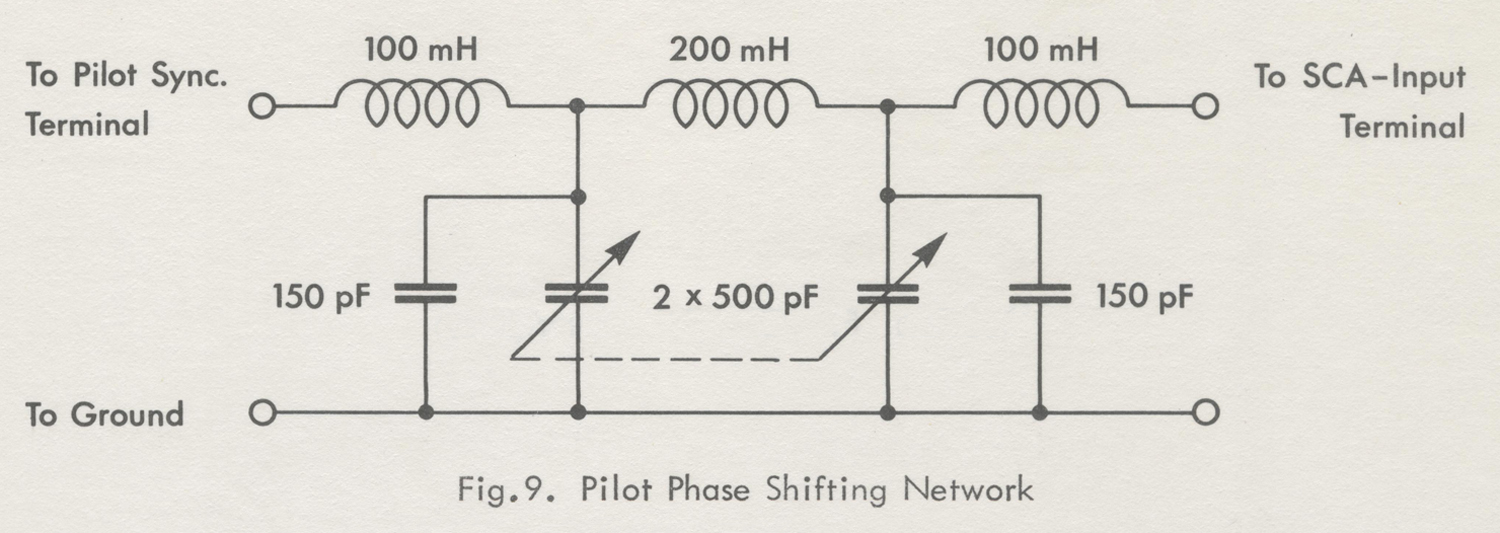 At the plant, the pilot signal phase has been internally adjusted to the standard value. If a non-standard pilot phase is required, connect the variable low-pass filter as shown in Fig.9 between the PILOT SYNC. and SCA INPUT terminals, and release the PILOT button. The pilot amplitude will have the standardized value simply by turning the variable double -capacitor of the filter. See MAINTENANCE as regards finding the setting of the capacitor which gives the correct pilot phase.
If, moreover, a smaller non-standard pilot amplitude is wanted, shunt the PILOT SYNC. terminal (to which the input of the filter still is connected) with a variable resistor to ground, and then set the amplitude with this resistor.
2) Using the Stereo Generator as a low-distortion audio signal generator.
Push FUNCTION SELECTOR button SET DEV. and one of the MODULATION FREQUENCY buttons. 80 Hz, 1 kHz or 5 kHz, . (80 Hz, 1 kHz or 10 kHz for SMG1S2.) The signal at the COMPOSITE OUTPUT terminals will now be a pure sine-wave of the chosen frequency. Voltage: 0-5 volts rms, depending on the setting of AMPLITUDE and LEVEL.
Distortion: Less than 0.2%. Load impedance: minimum 1500 Ω.
3) FM-Modulating the RF-UNIT with an external modulation signal.
a) Modulation frequencies approx. 40 Hz – 15 kHz.
Push FUNCTION SELECTOR button marked EXTERNAL MODULATION
R = L (M)
Connect the external audio signal generator to L INPUT terminals.
Set the output voltage of the audio signal generator to full deflection (100%) on the meter, if 75 kHz peak deviation is wanted, and proportionally lower for smaller peak deviations.
b) Modulation frequencies approx. 10 kHz – 75 kHz.
Push FUNCTION SELECTOR button marked MOD. OFF.
Connect the external signal generator terminals.
Set the output voltage of the signal generator to full deflection (100%) on the meter, if 75 kHz peak deviation is wanted, and proportionally lower for smaller peak deviations. 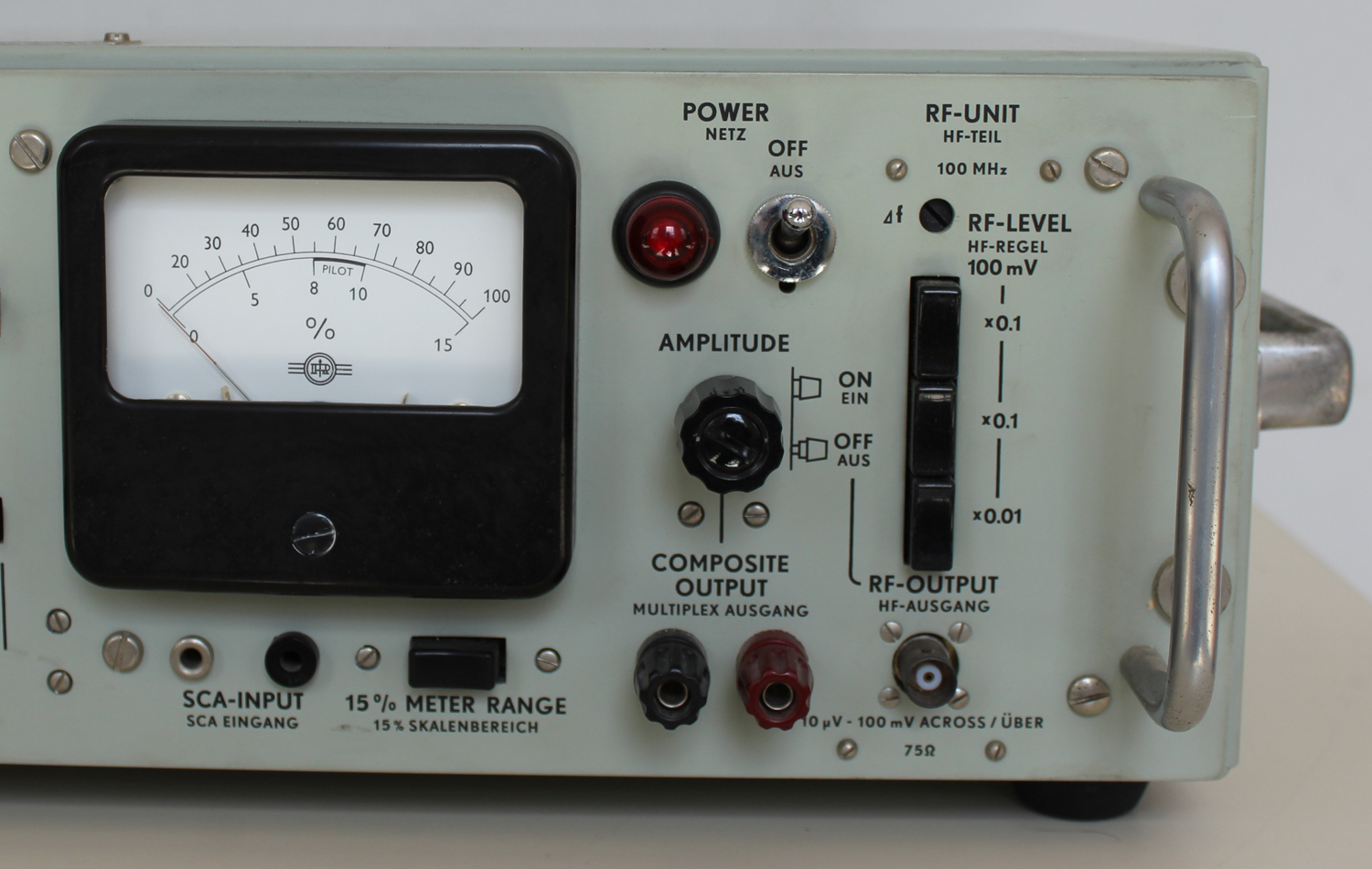
Section F. Circuit Description
INPUT CIRCUITS, FUNCTION SELECTOR and INPUT AMPLIFIERS
The input circuits are connected to the input amplifiers so as to provide the required operating modes.
Input Amplifiers
The left and right input amplifiers are two identical amplifiers equipped with three transistors each. Heavy negative feedback is used to obtain constant amplification and small phase error. 50 μsec (European standard) or 75 μsec (American standard) pre-emphasis can be switched into the feedback loop.
The outputs from these amplifiers feed the switch modulator.
Audio Input
The Audio Input provides for stereo inputs from tapes and records. A two-gang potentiometer provides for sensitivity control, and two low-pass filters with a cut-off frequency of 15 kHz suppress spurious signals, particularly at 19 kHz.
In position AUDIO), the Function Selector connects the Audio Input to the input amplifiers.
L and R Input
This input circuit is intended for measurements where external audio signal generators are used.
With Function Selector in position L & R, the L Input and R Input terminals are coupled to the left and right input amplifier respectively.
In position R = L, the L Input terminals are coupled to the parallel-connected left and right input amplifiers.
In position R = -L, the L Input terminals are connected to the left input amplifier. The input signal to the right input amplifier is nearly half the sum of the output signals from the two input amplifiers. The summation is a bit skewed to obtain exactly balanced driving signals to the switch modulator.
Operating Modes MOD. OFF and SET DEV.
With Function Selector in position MOD. OFF, the connection between the switch modulator and the low-pass filter in front of the output amplifier is open. Therefore there is either no input signal to the output
amplifier, or, if the PILOT button is pushed, the input signal is the pilot signal only.
In position SET. DEV., the Modulating Oscillator supplies a pure sine-wave signal to the output amplifier.
Internal Modulation
With Function Selector in position R = L, the left and right input amplifiers are parallel-fed from the built-in modulating oscillator.
In position R = -L, the left input amplifier is fed from the modulating oscillator, and the input signal to the right input amplifier is nearly half the sum of the output signals from the two input amplifiers.
In this way balanced driving signals to the switch modulator are obtained.
In position L ONLY, the left input amplifier is fed from the modulating oscillator, and the right input amplifier is short-circuited to ground. Vice versa in position R ONLY.
MODULATING OSCILLATOR
The modulating oscillator is a 3-transistors1 Wien-bridge RC-oscillator with a thermistor for amplitude stabilization.
Three modulation frequencies can be chosen by switching the capacitors in the Wien-bridge circuit.
The modulation level is set by means of a screw-driver adjustment. The oscillator signal is accessible from the Sync. terminals».
§§§
 Il testo prosegue nella seconda parte; per consultarla scrivere “SMG1” su Cerca.
Foto di Claudio Profumieri; elaborazioni, ricerche e testo a cura di Fabio Panfili.