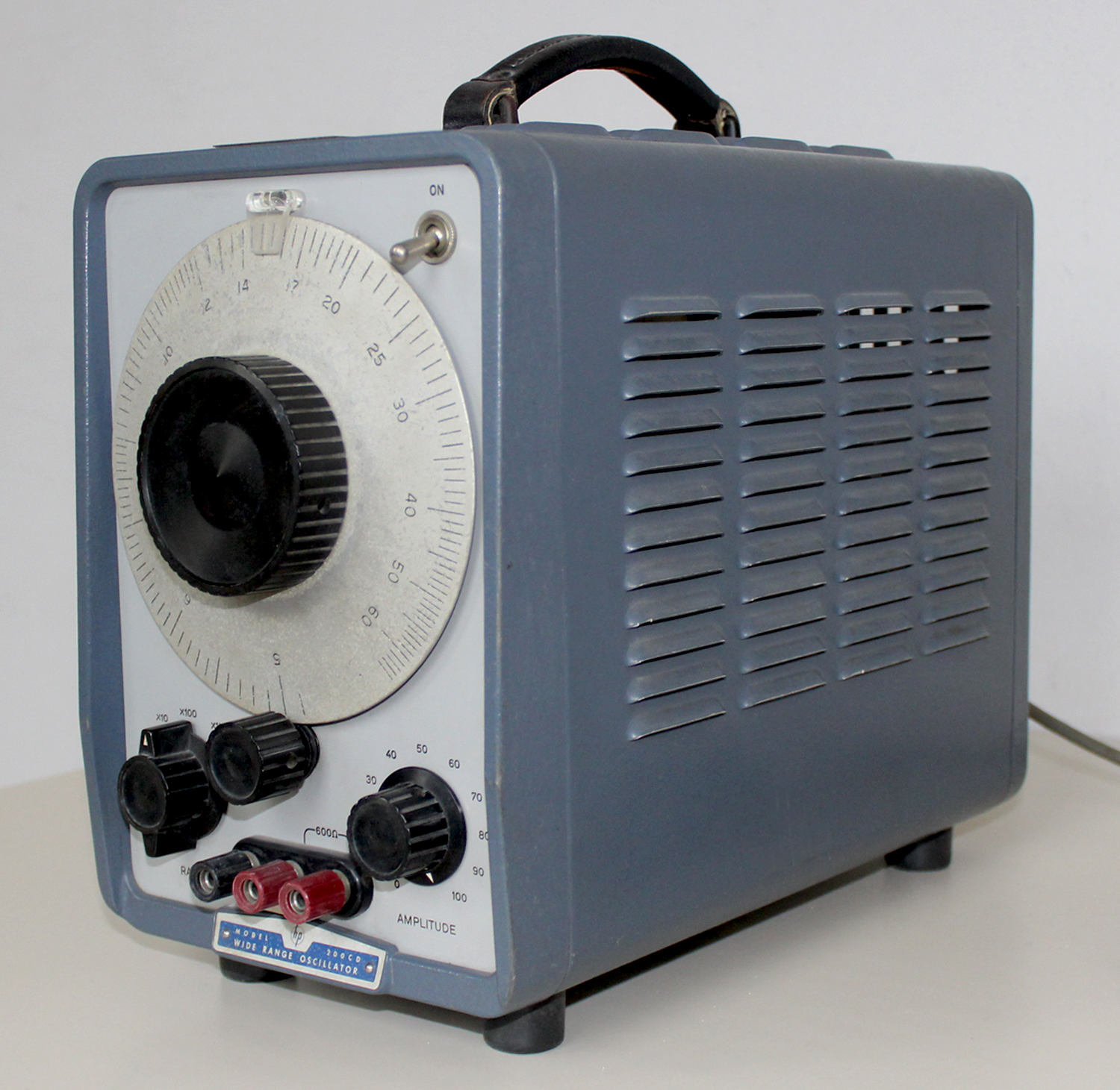
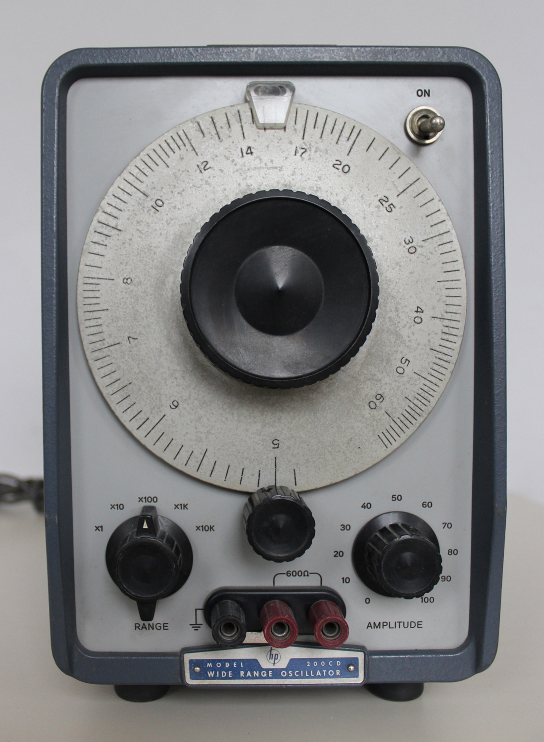
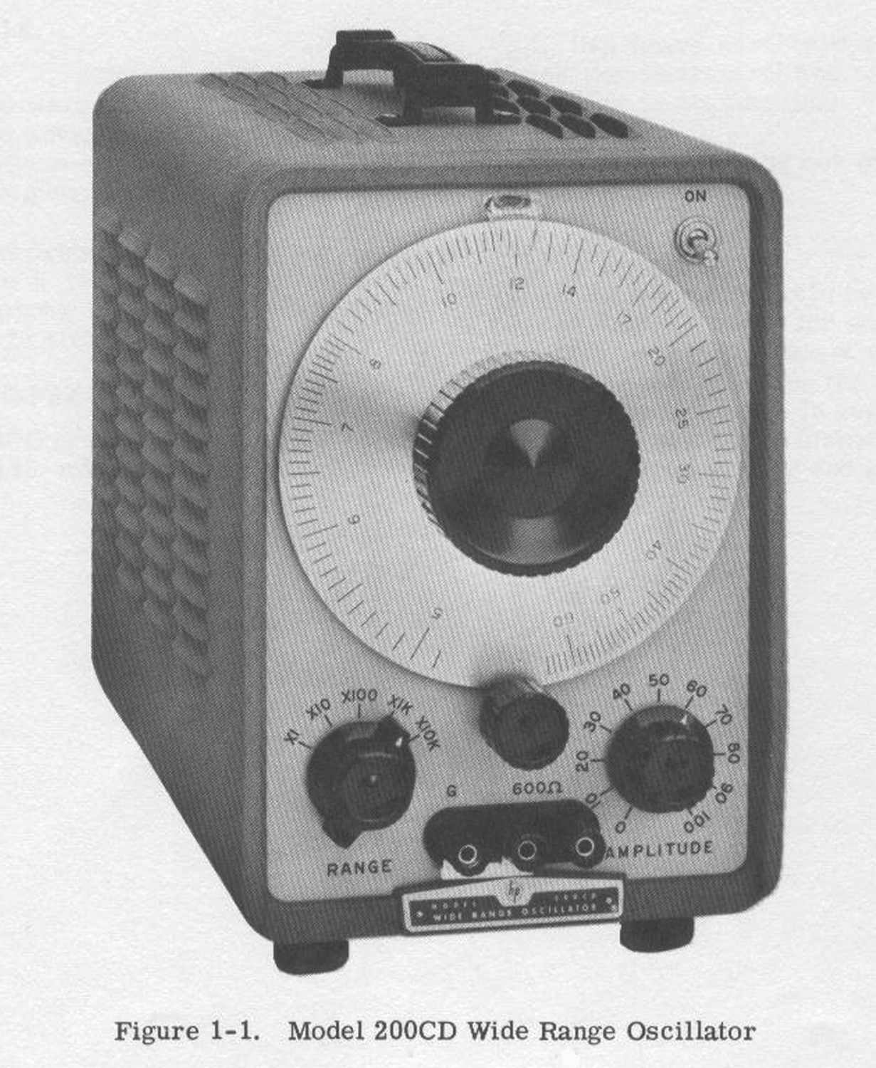
 Wide Range Oscillator Hewlett Packard, mod. 200CD, serial numberG 730-03469,W.-Germany.
Dono della Fondazione Carlo e Giuseppe Piaggio – Genova.
Nell’estratto di inventario della Sezione Elettronica, in data febbraio 1968 al n° 198 si legge: “N° D 42324-35. Oscillatore 230 V ( HP 200CD)”. Mentre scriviamo questa scheda purtroppo non disponiamo dell’inventario generale D dell’epoca per ulteriori dettagli, ma sappiamo che gli esemplari acquistati erano due.
In internet si trova molta documentazione che riguarda lo strumento; per consultare il manuale di istruzioni si può andare all’indirizzo:
http://www.hparchive.com/Manuals/HP-200CD-Manual-SNP_605.PDF
Il testo che segue con le relative figure è tratto dal manuale di istruzioni conservato presso la Sezione Elettronica.
§§§
 SECTION I
GENERAL INFORMATION
1-1. DESCRIPTION.
1-2. The Model 200CD Wide Range Oscillator generates frequencies of excellent waveform in the subsonic, audio, and ultrasonic ranges (5 cycles to 600 kc, in five overlapping decade bands). The Mode1200CD includes new design features which result in still finer performance than previous Hewlett-Packard instruments. Special circuitry ensures an output voltage of low distortion and high stability with any output load impedance from zero ohms to open circuit. Usefulness of the oscillator has been extended by designing the 200CD output circuit so that the instrument may be operated balanced as well as unbalanced and by providing a 600-ohm impedance match.
1-3. The Model 200CD is easy to operate: frequency and amplitude of the output voltage are set merely by operating dials on the control panel. The easily- read, 6-inch diameter frequency dial is calibrated over 300° of arc, and has an effective scale length of approximately 80 inches.
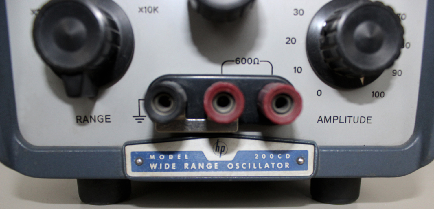
1-4. The Model 200CD furnishes up to 10 volts into a 600-ohm load (20 volts open circuit) at any frequency from 5 cps to 600 kc. A bridged tee variable attenuator in the output circuit controls the output power.
1- 5. The Model 200CD provides an ideal signal source for testing servo and vibrating systems, medical and geophysical equipment, audio amplifier circuits and transducers, sonar and supersonic apparatus , carrier telephone systems, video frequency circuits, and low radio-frequency equipment.
1-6. DIFFERENCES BETWEEN INSTRUMENTS.
1-7. Hewlett-Packard uses a two-section eight-digit serial number (000-00000). If the first three digits of the serial number on your instrument do not agree with those on the title page of this manual, change sheets supplied with the manual will define differences between your instrument and the Model 200CD described in this manual.
1-8. BACKDATING SHEET.
1-9. A backdating sheet that makes this manual applicable for instruments with serial prefixes to 103, is provided in The Appendix of this manual.
SECTION II
PREPARATION OF USE
[Omissis…]
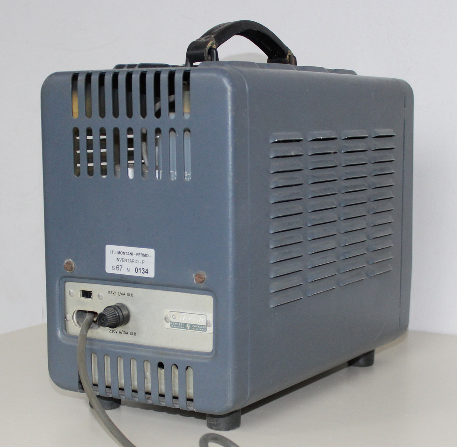
2-6. POWER REQUIREMENTS.
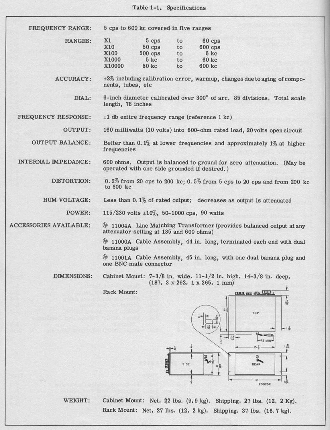
2-7, The Model 200CD requires a power source of 115/230 volts +10%, 50/1000 cps, 75 watts.
[Omissis…]
2-11. 230-VOLT OPERATION.
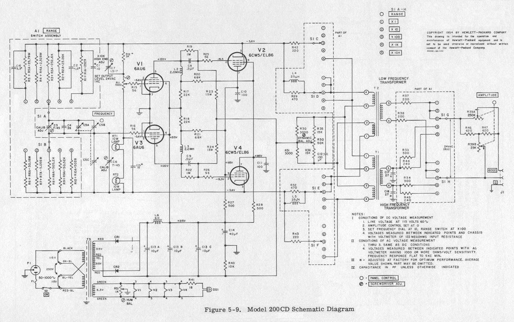
2-12. The Model 200CD is normally wired for operation from a nominal 115-volt supply. Operation from a 230-volt source is easily accomplished by reconnecting the dual 115-volt primary windings of the power transformer from a parallel configuration to a series configuration. (See figure 5-9). At the time of the change, replace the 1. 25 amp, slow-blow line fuse with a 0.6 amp, slow-blow line fuse.
 SECTION III
OPERATING INSTRUCTIONS
3-1 . INTRODUCTION.
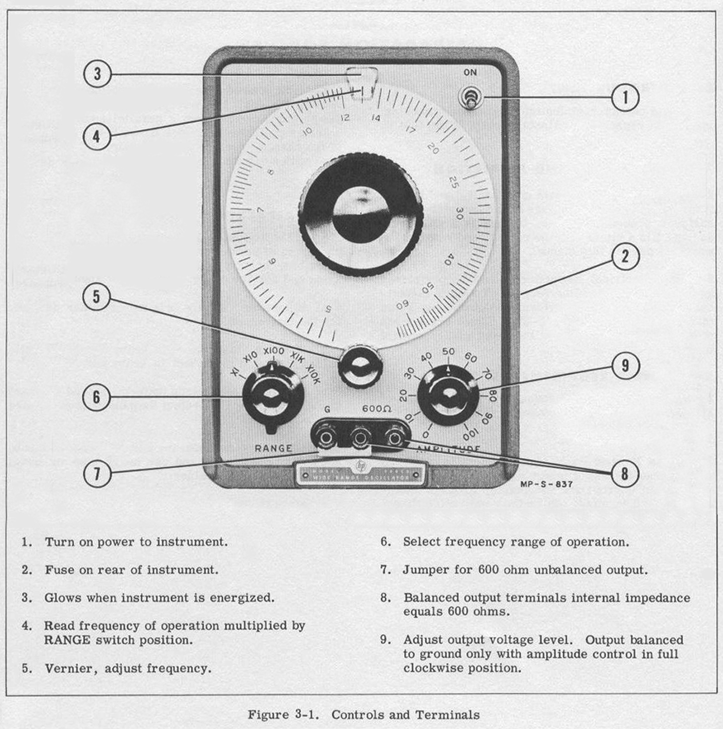
3-2. This section contains operating instructions for the Model 200CD Wide Range Oscillator. Figure 3- 1 gives basic operating instructions. The remainder of this section supplements these instructions.
3-3. OPERATION.
3-4. ON. The oscillator is ready for use as received from the factory and will give specified performance after a short warmup period. Turn oscillator on and allow approximately five minutes to warm up. Where maximum accuracy is desired, this warm-up period should be extended to at least thirty minutes.
3-5. RANGE. The RANGE is selected with the five position RANGE switch_ The position of this switch indicates the multiplying factor for the frequency dial calibration.
3-6. FREQUENCY dial. The frequency dial varies the frequency between the RANGE switch steps. The dial is calibrated from 5 to 60 and its indication multiplied by the factor indicated by the RANGE switch will give the actual output frequency of the oscillator. The small knob below the frequency dial is a vernier control for the dial.
3-7. OUTPUT CIRCUIT OPTIONS. The output circuit of the Model 200CD may be arranged for balanced or unbalanced operation. Typical connections for each are indicated in figure 3-2.
a. Unbalanced Operation. To operate with sidegrounded, a strap is placed between the G terminal,as indicated in figure 3-2A,
b. Balanced Operation. Connections for balanced operation are indicated in figure 3-2B. (The broken line from the ground terminal indicates the output circuit is balanced to ground, within the tolerances given below.
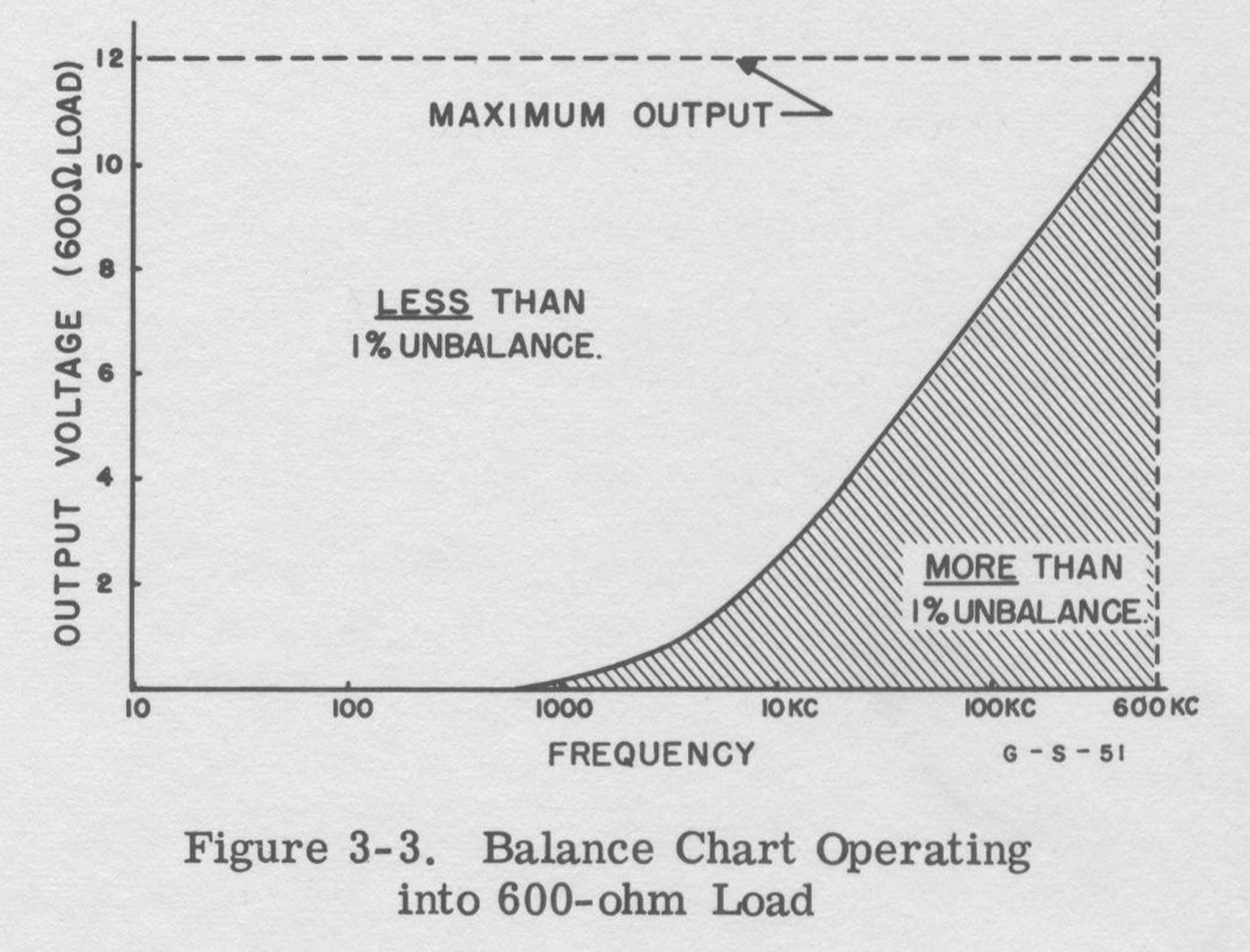
3-8. The AMPLITUDE control in the output circuit is a bridged-T attenuator and at any setting except minimum attenuation unbalances the circuit. Therefore, for balanced operation the AMPLITUDE control must be set for maximum output (full clockwise). Output balance also is a function of frequency because of capacitive feed-through at higher frequencies. Up to 10 kc, however, unbalance is less than 0.1%, and at B00 kc is approximately 1%. If small outputs are desired, or if balance at higher frequencies is critical, turn the AMPLITUDE control maximum clockwise, and connect an external attenuator, designed for the frequencies involved, between the Model 200CD and the load.
3-9. A balanced output may also be obtained over the full range of the AMPLITUDE control by using an hp AC-60A/B Line Matching Transformer at the output terminals of the oscillator.
3-10. The following chart indicates the area where within 1% of balance may be obtained. This chart indicates balance obtainable at various settings of the AMPLITUDE control when operating into a 600-ohm load. Where other values of load are used, the chart does not apply directly but does apply for settings of the AMPLITUDE control that would produce the indicated voltage across at 600-ohm load.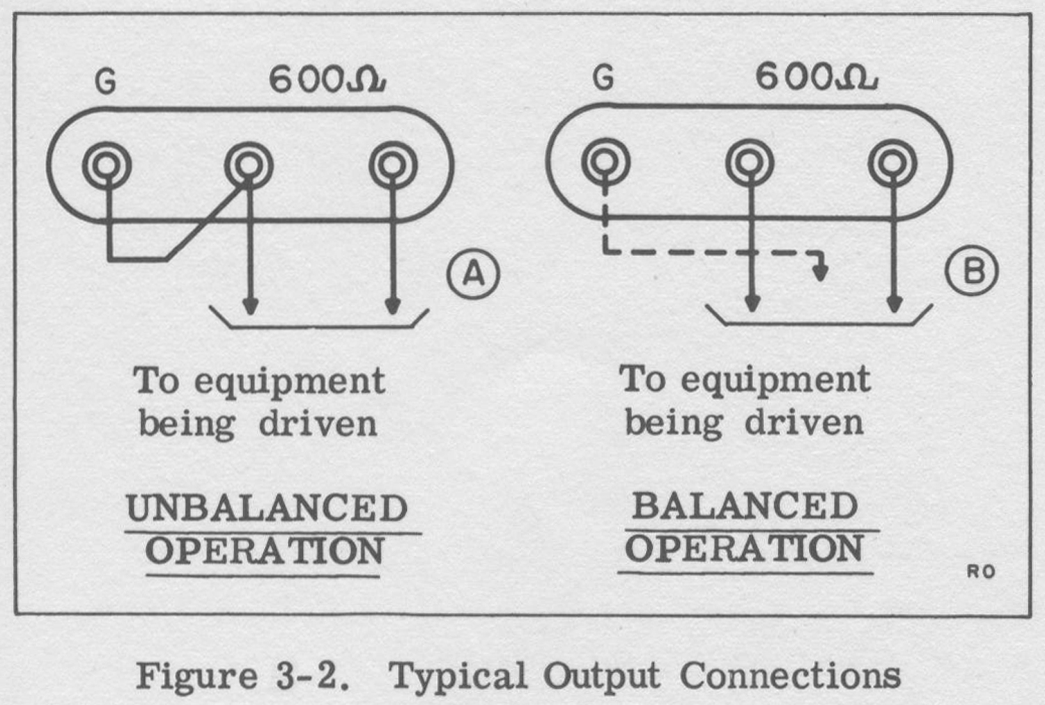
 SECTION IV
THEORY OF OPERATION
4-1 . GENERAL.
4-2. The Model 200CD Wide Range Oscillator uses a balanced (push-pull) oscillator circuit from which the output is taken directly, avoiding the complication and possible distortion of an isolating amplifier. Reaction of the load on the oscillator is avoided by the use of a zero source impedance output stage. This arrangement results in a simple, trouble-free circuit having low distortion and high stability over the entire frequency range.
4-3. Functionally, the circuits of the Model 200CD include a frequency-controlling bridge and balanced push—pull amplifier which constitute the oscillator circuit, an output circuit which may be arranged either for balanced or unbalanced operation, and a power-supply circuit. These are shown in block diagram form in figure 4-1 and in detail in the schematic diagram.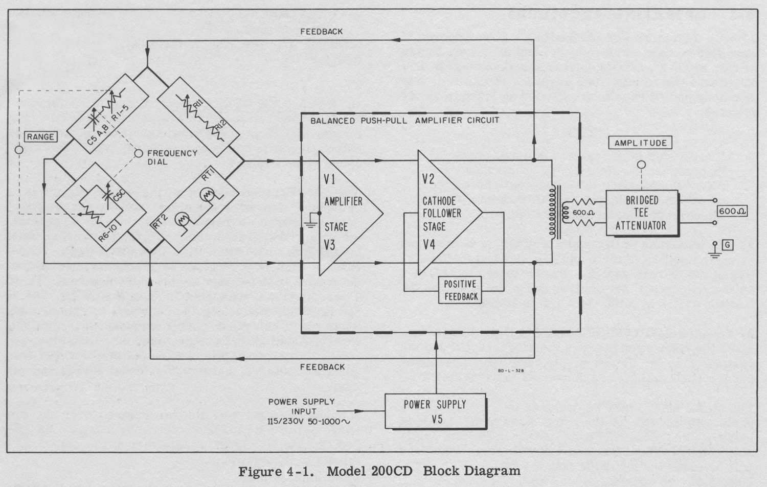
4-4. FREQUENCY-CONTROLLING BRIDGE.
4-5. The frequency-controlling circuit is arranged as a floating bridge, symmetrical with respect to ground. With no connection to ground on any terminal of the bridge, stability of calibration is assured since any stray capacity or leakage to ground present at the bridge output terminals does not shunt either the frequency-controlling or amplitude-stabilizing arms of the bridge. The frequency- controlling components (RC networks which are varied by operation of the RANGE switch and frequency dial) comprise two arms of the bridge, while the amplitude-stabilizing components (a voltage divider which includes a thermally- sensitive resistance) comprise the other two arms. The amplitude is stabilized at such a level that the amplifier tubes are operated in the substantially linear portion of their characteristics, which, together with the large negative feedback at harmonic frequencies, results in a very pure sine wave oscillation.
4-6. The bridge is fed by the balanced voltage developed at the cathodes of V2 and V4 in the output of the balanced amplifier. The output of the frequency-controlling branch of the bridge is applied to the grid of V3 and the output of the amplitude-stabilizing branch is applied to the grid of V1. The manner in which the voltage-versus-frequency and phase-versus-frequency characteristics of an RC network can be utilized with an amplifier of proper design to achieve an oscillator which delivers a voltage of excellent stability and wave-form is well covered in texts such as Terman & Pettit’s Electronic Measurements.
4-7. Variable resistor R11 is provided for adjustment of the amplitude-stabilizing branch of the bridge should it be found alter replacement of lamp RT1 or RT2 that less or more than rated voltage is being delivered to the output terminals.
4-8. Variable capacitors C3, C6, andC7 are adjusted at the factory for optimum calibration and amplitude constancy with frequency. They should not require adjustment unless the RANGE switch is replaced.
4-9. AMPLIFIER.
4-10, The oscillator amplifier is a balanced push-pull circuit including a voltage -amplifier stage (V1, V3) and a special cathode-follower stage (V2, V4). Criss-cross positive feedback is used in the cathode-follower stage to provide an essentially zero output impedance as seen by the cathode-to-cathode load. The feedback paths are from the plate of V2 to the control grid and screen of V4, and from the plate of V4 to the control grid and screen of V2. The degree of the positive feedback is a function of the load and increases as the load impedance decreases, thus tending to maintain the output constant regardless of load. Self-oscillation in the amplifier circuit is prevented by proper choice of resistance in the feedback circuits and by controlling plate and cathode impedances over the entire frequency range of the oscillator. The output stage is protected against a cathode-to-cathode short circuit by the resistors in series with the transformer secondaries. These resistors also make the oscillator present a 600-ohm impedance to the attenuator.
4-11. OUTPUT CIRCUIT.
4-12. Transformer coupling provides isolation between the oscillator circuit and the output circuit, and allows the output to be obtained either balanced or unbalanced. Since a single transformer will operate suitably over only a part of the frequency range covered 200CD, two transformers are provided. Connections between cathode-followers V2 and V4 and the proper transformer for the band in use are set up by the RANGE switch. The Secondary windings of the coupling transformers supply a conventional bridged tee attenuator, the setting of which is adjusted by operation of the AMPLITUDE control on the front panel. As the control is turned counterclockwise, the loss inserted by the attenuator is increased. The source impedance at the output terminals is 600 ohms.
4-13. With attenuator set for minimum loss, the output circuit is arranged for balanced operation, and is so designed that for frequencies up to 10 kc, stray capacity and leakage resistance will cause less than 0.1% unbalance. Unbalance at 600 kc is approximately 1%.
4-14. When it is desired to operate unbalanced, ground should be connected to the center output terminal, the termination for the connection brought out from terminal 6 of output transformers T1 and T2. Proper operation cannot be obtained if the ground is connected to the Bide of the circuit which includes the attenuator».
§§§
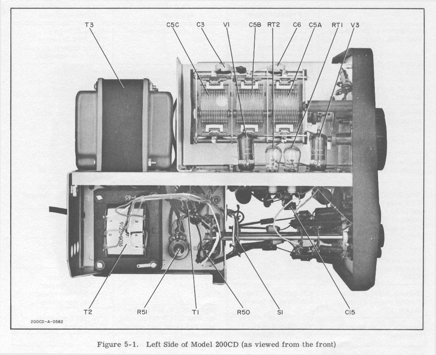
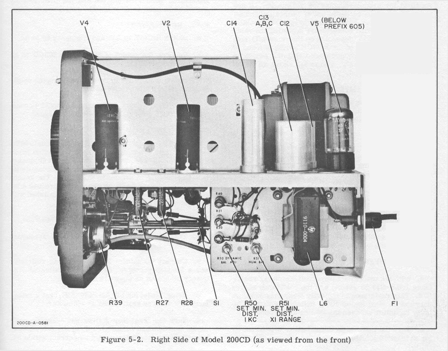
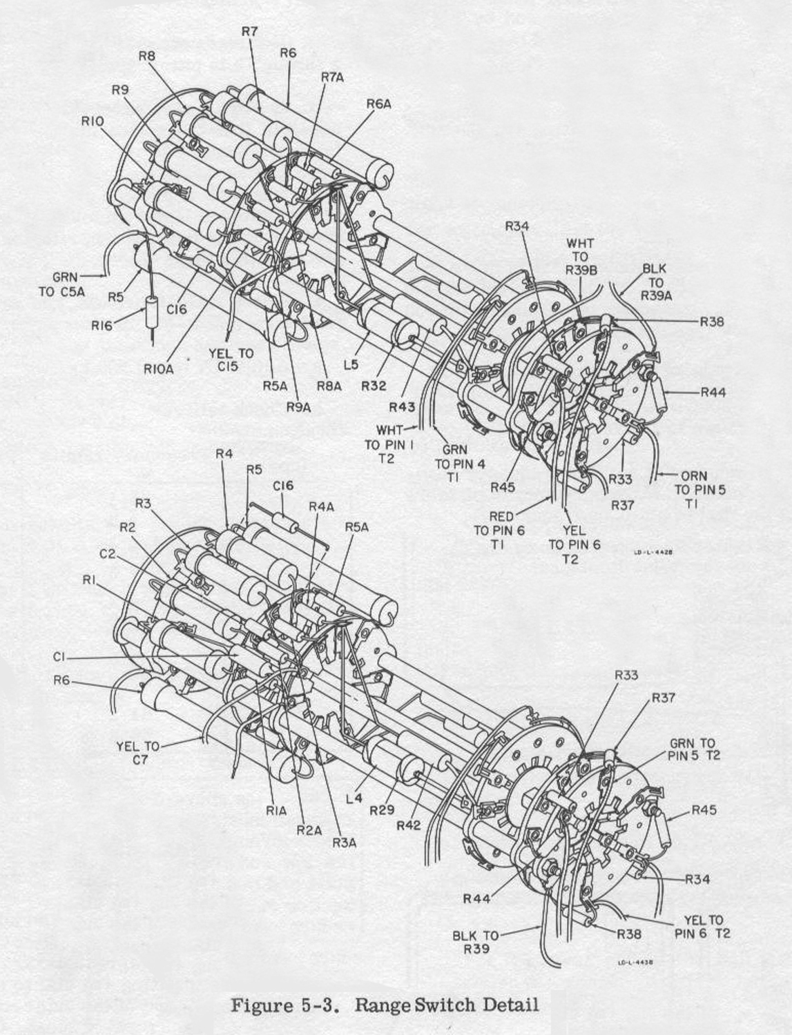
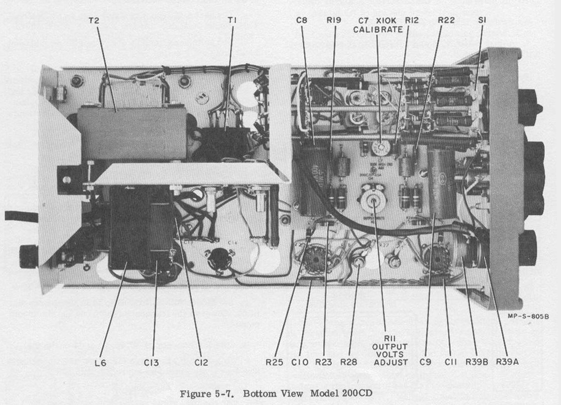
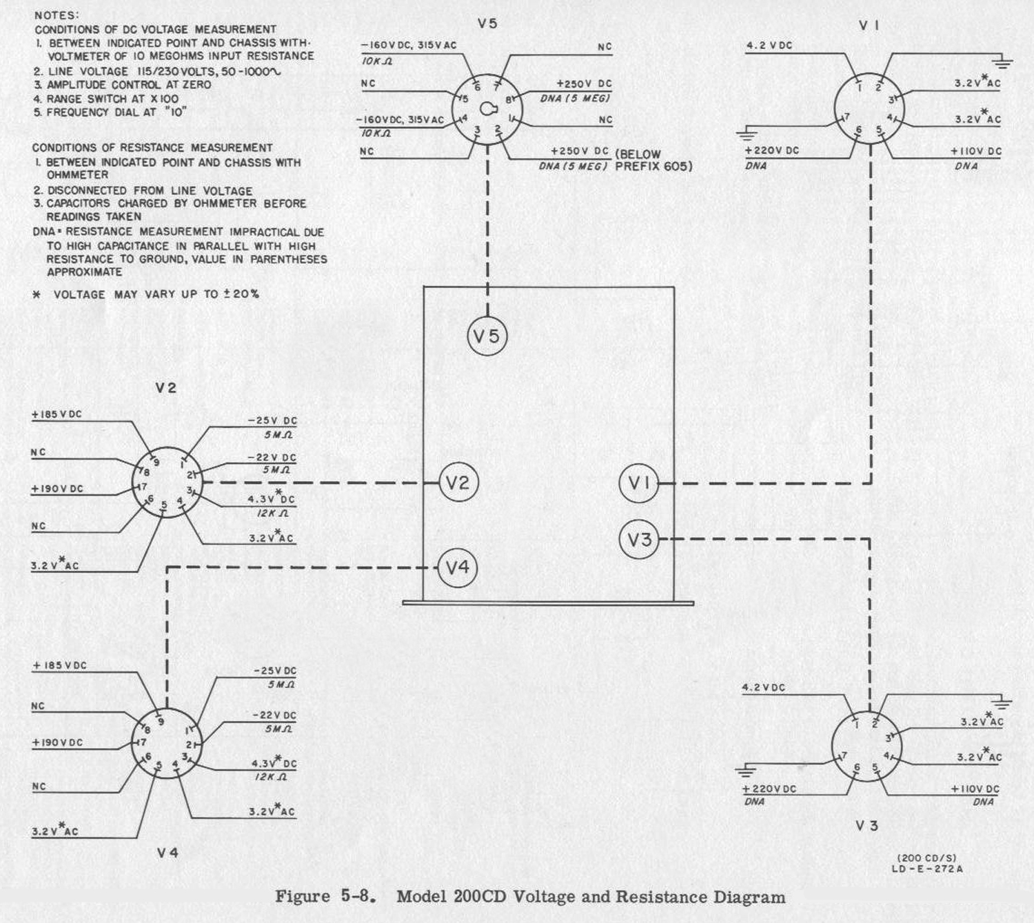
La sezione Maintenance è stata omessa insieme ad altre parti. Di queste abbiamo riportato alcune figure che riteniamo interessanti.
Per consultare la versione in italiano scrivere “200CD” su Cerca.
Foto di Claudio Profumieri, elaborazioni e ricerche di Fabio Panfili.
Per ingrandire le immagini cliccare su di esse col tasto destro del mouse e scegliere tra le opzioni.