 Wide Range R-C Oscillator TF 1370A, Serial N° 53336/08. Marconi Instruments Ltd. England.
Per ragioni indipendenti dalla nostra volontà per ora non possiamo accedere all’inventario dell’epoca, pur sapendo che si trova al n° 4002 ed è stato acquistato poco dopo il 17 gennaio 1966 (osservare il timbro in alto a destra). Riportiamo qui una prima parte del manuale di istruzioni custodito nell’archivio della Sezione Elettronica.
Una parte successiva del manuale è riportata nella scheda relativa al Wide Range R-C Oscillator TF 1370°, Serial N° 54110/053. Marconi Instruments Ltd. England. Per consultarla scrivere: “54110/053” su Cerca.
In rete il manuale di istruzioni è rinvenibile ai seguenti indirizzi:
https://ia800202.us.archive.org/35/items/marconi_tf1370a/tf1370a.pdf
http://bee.mif.pg.gda.pl/ciasteczkowypotwor/Marconi/tf1370a.pdf
Mentre una rivista nella quale vi è una interessante presentazione dello strumento si trova all’indirizzo: https://www.americanradiohistory.com/Archive-Marconi-Instrumentation/Marconi-1961-03.pdf
§§§
 «1 GENERAL INFORMATION
1.1 FEATURES
The TF 1370A is a general-purpose sine wave generator covering the frequency range 10 c/s to 10 Mc/s. It also delivers a high-quality square wave output at frequencies between 10 c/s and 100 kc/s.
The instrument is primarily a signal source for measurements and tests on audio and video amplifiers and networks. With its four output impedances – 600, 130, 100, and 75 Ω – it is suitable for use with transmission lines, filters, attenuators, etc.
Among other applications as a sine wave generator is that of providing the excitation voltage for a. f. and r. f. bridges. And the quality of the square wave output also renders the instrument particularly effective for such purposes as rapid testing of audio amplifier bandwidth.
The signal originates in a Wien bridge oscillator covering 10 c/s to 10 Mc/s in six decade bands, the top band extending from 1 to 10 Mc/s. A single scale is used for the four lower bands and separate scales for the two upper bands; this gives a total scale length of 105 inches and makes a 1% change in frequency easily discernible. Speed and precision of tuning are reconciled by a dual-ratio control, 3:1 for rapid adjustment and 18:1 for fine tuning.
TF 1370AR is a rack-mounting version of the TF 1370A and is supplied, complete with dust cover, for mounting in a standard 19 inch rack.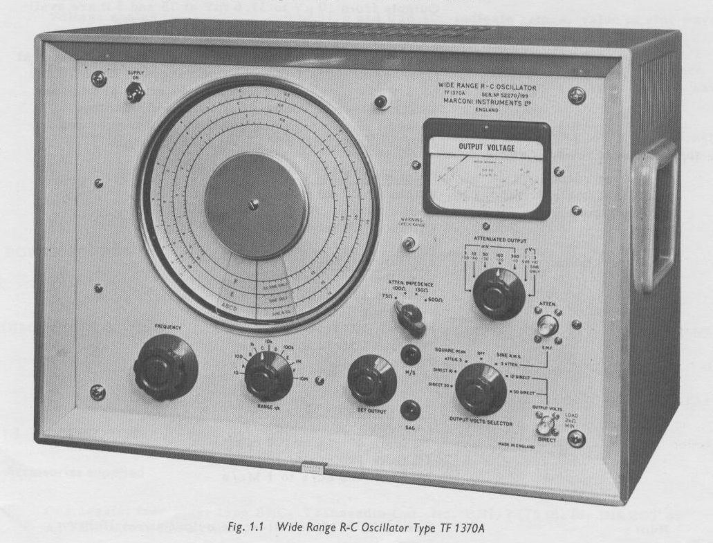 1.2 DATA SUMMARY
FREQUENCY
Range : Sine waves : 10 c/s to 10 Mc/s in six decade bands. Square waves; 10 c/s to 100 kc/s in four decade bands.
Accuracy : Within ±2% ±1 c/s.
Stability: Drift does not exceed :0. 1% Over a 15 minute period after 1 hour warm-up.
SINE WAVE OUTPUT
Range (via attenuator): 1 mV to 3.16 V e.m.f. at switch selected source impedances of 75, 100, 130 and 600 Ω unbalanced. Controlled by attenuator with six 10 dB steps and potentiometer in conjunction with level monitor.
Attenuator accuracy is ±1 dB overall on resistive load.
Outputs from 10 µV to 31.6 mV at 75 and 5 Q are available by using ×100 Attenuator Pad TM 6454.
Range (direct): Up to 31.6 V p.d. across loads of 2.2 KΩ or greater, at frequencies up to 1 Mc/s. Two ranges of up to 10 and 31.6 V are provided by switched potential divider and potentiometer in conjunction with level monitor.
Nominal impedances are 650 Ω on 10 V range, and 25 Ω in series with 500 µF on 31.6 V range.
Frequency response (via attenuator and without adjusting meter):
Relative to 1 kc/s
Within ±0.25 B from 100 c/ to 1Mc/s.
Within ±0.5 dB from 10 c/s to 100 c/s.
Within ±1 dB from 1 Mc/s to 10 Mc/s.
Distortion factor :
3 V output level
Less than :
2% from 20 c/s to 100 c/s
0.5% from 100 c/s to 100 kc/s
1% from 100 kc/s to 1 Mc/s
2% from 1 Mc/s to 4 Mc/s
5% from 4 Mc/s to 10 Mc/s
30 V output level
Less than:
2% from 20 c/s to 100 c/s
1% from 100 c/s to 100 kc/s
2% from 100 kc/s to 1Mc/s
Hum: Less than 0. 1% of ful1—scale output above 10 mV.
SQUARE WAVE OUTPUT
Range: 1 mV to 3.16 V peak via attenuator, and up to 31.6 V peak direct.
Other details as for sine wave output except that source impedance is increased by 250 Ω at maximum output step of attenuator.
Frequency response (without adjusting meter):
Relative to 1kc/s
Within:0. 3 dB from 10 c/s to 100 kc/s.
Rise time:
0.75 µsec or less at ful1-sca1e output.
0.4 µsec or less at 1/3 full-scale output.
Sag: Approximately 5% in a. 2.2 kΩ load at 20 c/s.
Adjustable by panel preset.
Mark/space ratio: 50/50 ±5%. Adjustable by panel preset.
LEVEL MONITOR
Voltage scales : 0 to 31. 6 and 0 to 10; indicate r.m.s. value of sine wave and peak value of square wave with respect to zero.
Decibel scales : 0 to -20 with respect to full-scale; also 0 dB reference point indicating 1 V peak to peak sine wave or square wave across a 75 Ω load.
Accuracy: ±3% of full-scale for sine waves up to 1 Mc/s; additional ±2% of reading for square waves, and for sine waves up to 10 Mc/s.
POWER SUPPLY: 200 to 250 V and 100 to 150 V, 45 to 65 c/s, 150 W.
DIMENSIONS & WEIGHT :
Height 14 in (36 cm) Width 20 in (51 cm) Depth 11 in (Z8 cm) Weight as lb (17 kg)
1.3 ACCESSORIES
Accessories supplied
One coaxial free plug, type BNC, Transradio Cat. No. BN1/7 (75 Ω); for DIRECT or ATTEN output connections.
Accessories available 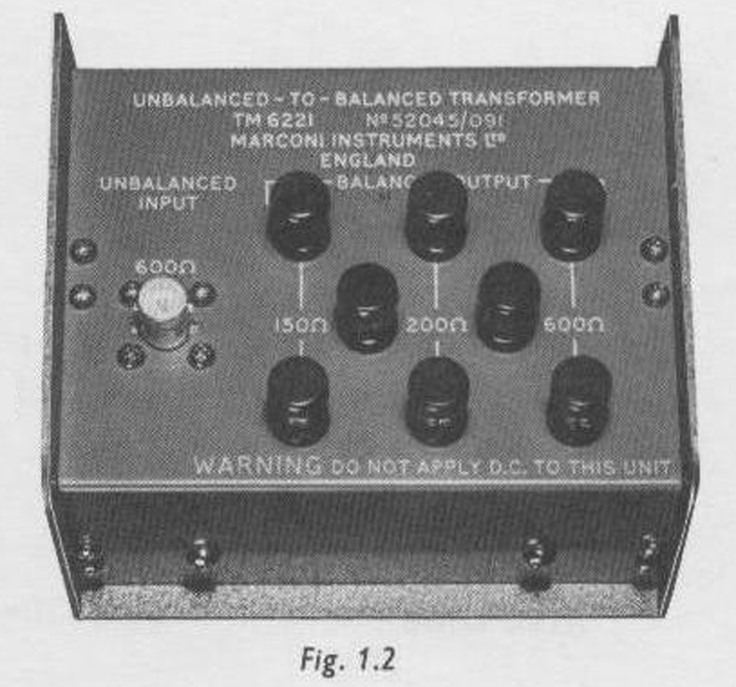
(1) UNBALANCED—TO—BALANCED TRANSFORMER
TYPE TM 6221
This transformer provides balanced signals at 600, 200, or 150 Ω source impedance, and is for use with sine wave outputs in a frequency range 10 c/s to 100 kc/s.
Connections: BNC socket for input; terminals for outputs, centre-tap, and earth.
Impedance ratios: 600 Ω to 600, 200, and 150 Ω.
Insertion loss (at 1 kc/s] : 0.5 dB approximately.
Out-of-balance: Not exceeding 0.2 dB from 150 c/s to 50 kc/s; not exceeding 1 dB at 20 c/s or 100 kc/s.
Response at secondary (with respect to 1 kc/s): ±0. 2 dB from 150 c/s to 50 kc/s; not below -1 dB at 2.0 c/s or 100 kc/s.
Distortion factor: ( loaded and fed by a pure sine wave at 3 V e.m.f.): 100 c/s to 50 kc/s, not exceeding 0.2%; 70 c/s to 100 c/s and 50 kc/s to 100 kc/s, not exceeding 0.4%.
Dimensions & weight : Height 3 ¼ in (8.5 cm) Width 4 ⅞ in (12.5 cm) Depth 4 in (10.5 cm) Weight 2 ¼ lb (1.1 kg)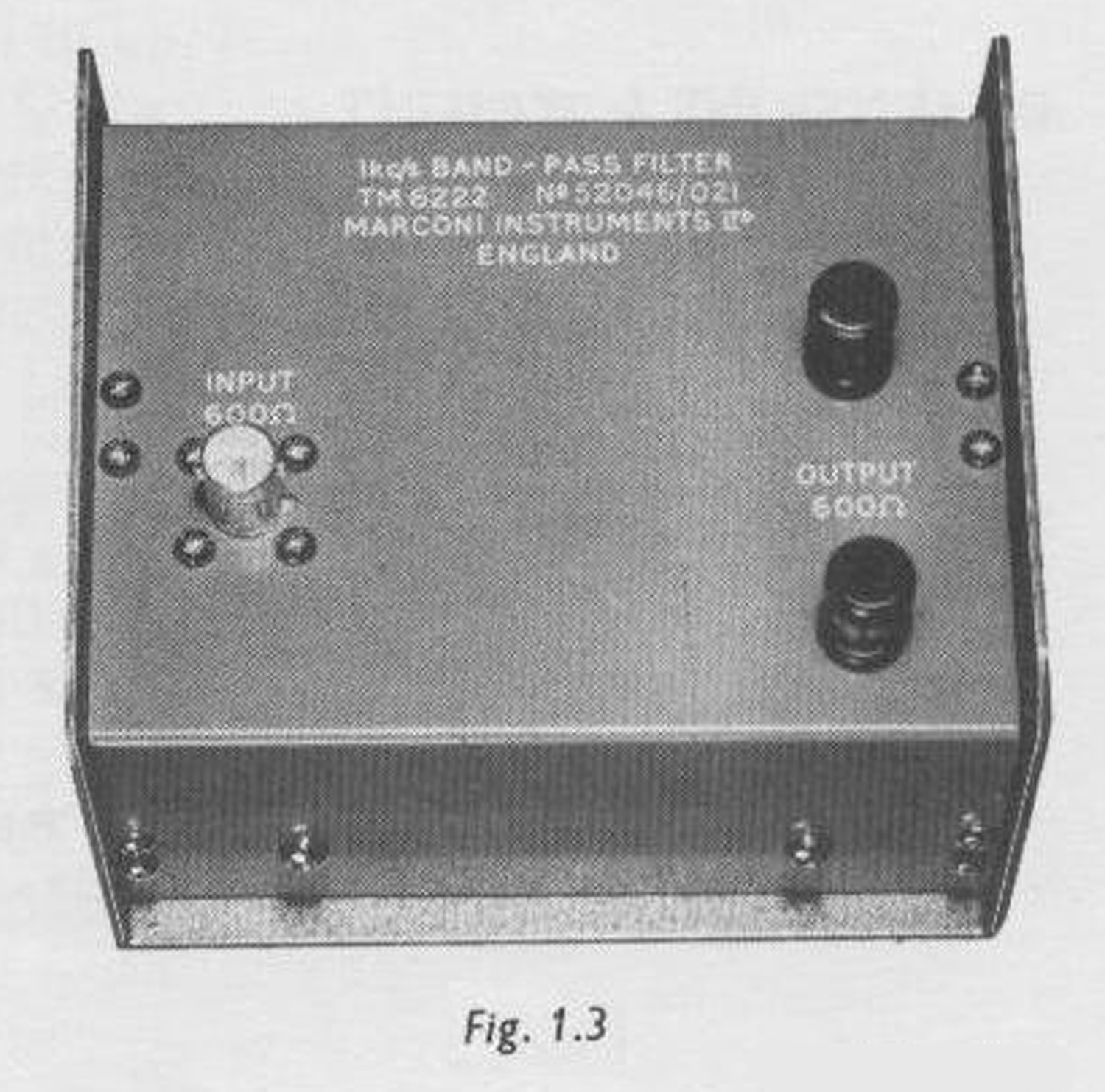 (2) 1 kc/s BAND-PASS FILTER TYPE TM 6222
This device. in series with the instrument, passes a pure 1 kc/s signal for applications requiring a very pure waveform.
Connections : Input, BNC socket; output, terminals
Impedance : 600 Ω ±10% when terminated by 600 Ω.
Insertion loss (at optimum pass frequency) : Not exceeding 1 dB. 3 dB Pass band: ±90 c/s approximately.
Distortion factor (loaded and fed by TF 1370A): Not exceeding 0.02%, feeding 250 mV to load; not exceeding 0.1% feeding 1 V to load.
Dimensions & weight: Height 3 ¼ in (8.5 cm) Width 4 ⅞ in (12.5 cm) Depth 4in (10.5 cm) Weight 2 ¼ lb (1.1 kg)
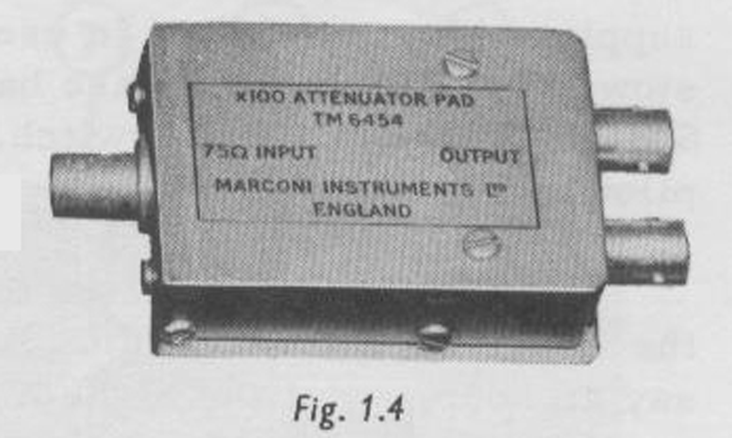
(3) ×100 ATTENUATOR PAD TYPE TM 6454
This device enables reduced outputs to be obtained down to 10 µV at a source impedance of 5 Ω or 75 Ω, and is for use with sine wave or square wave signals at all operating frequencies of the R—C Oscillator.
Connections : Three BNC sockets.
Loss : 40 dB ±1 dB.
Impedance : Input, 75 Ω; outputs, 75 and 5 Ω.
Maximum input : 6 V.
Dimensions & weight : Height 1 in (3 cm) Width 3 ¾ in (9.5 cm) Depth 1 ⅞ in (5 cm) Weight 4 oz (120 gm)
(4) COAXIAL LEAD TYPE TM 4726/136
Primarily intended for connecting (1), (2) or (3) above to the output sockets of the Oscillator.
Connections: BNC plug at each end.
Impedance: T5 Ω.
Length: 36 inches.
2 OPERATION
2.1 INSTALLATION
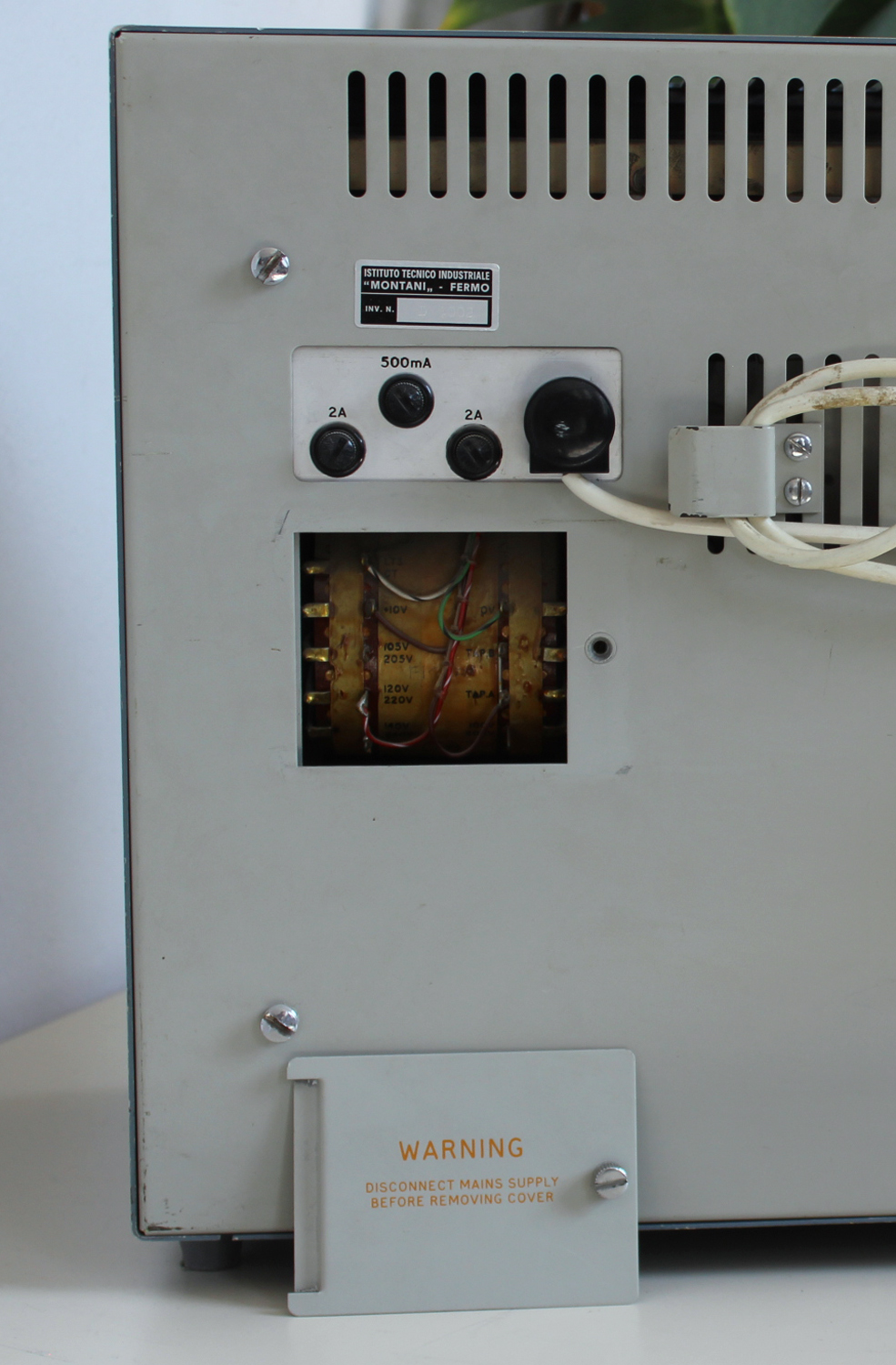
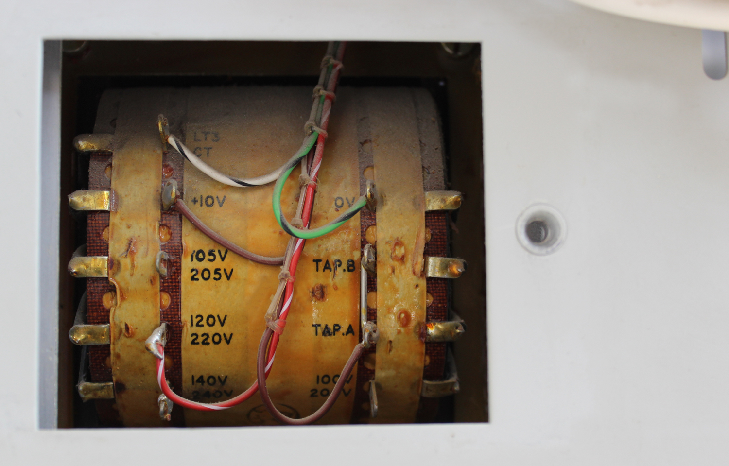
The instrument is normally dispatched ready for a 240 V supply unless otherwise ordered. Before switching on be sure that the connections on the mains transformer are correct for the supply voltage to be used – see Section 4.3. If the instrument is supplied in a plastic cover, completely remove this to ensure adequate ventilation.
2.2 SWITCHING ON
Connect the power lead to the a. c. supply socket; when not in use this lead is stowed in the left-hand case handle recess. Switch ON the SUPPLY switch. The red pilot lamp should glow.
Allow several minutes to elapse for the instrument to warm up. But allow longer, say an hour, when the highest stability is required.
2.3 SINE AND SQUARE WAVE OUTPUTS
Sine wave
Outputs from 1 mV to 3.16 V are available via a switched attenuator covering 60 dB in 10 dB steps. The signal level applied to the input of the attenuator is continuously variable and is monitored by a meter calibrated in open circuit voltage and decibels.
The output impedance can be set to 75, 100, 130, or 600 Ω , as required.
Low outputs down to 10 µV at 75 or 5 Ω can be obtained by using the ×100 Attenuator Pad available as an optional accessory.
High outputs up to 31.6 V, at frequencies up to 1 Mc/s, are delivered at a separate outlet; this outlet is controlled by a switched potential divider with a continuously variable input, and the meter indicates the voltage across the load. Switching to a higher frequency band during high output operation automatically lights a warning lamp to show that this is not an operative condition.
Square wave
Square Wave outputs up to 31.6 V peak are available at frequencies up to 100 kc/s. The warning lamp facility provided for high output sine wave operation also applies for square waves if a higher frequency band is selected. Output arrangements are similar to those for sine waves except that the meter indicates the peak amplitude with respect to zero, i. e. , half the peak-to-peak voltage.
Both sag and mark/space ratio are adjustable by front panel presets. Below 50 c/s, the sag can be adjusted to zero for any particular load; above 50 c/s, one zero setting is valid for all loads. The mark/space preset enables the ratio to be brought exactly to 50/50.
2.4 CONTROLS AND CONNECTORS
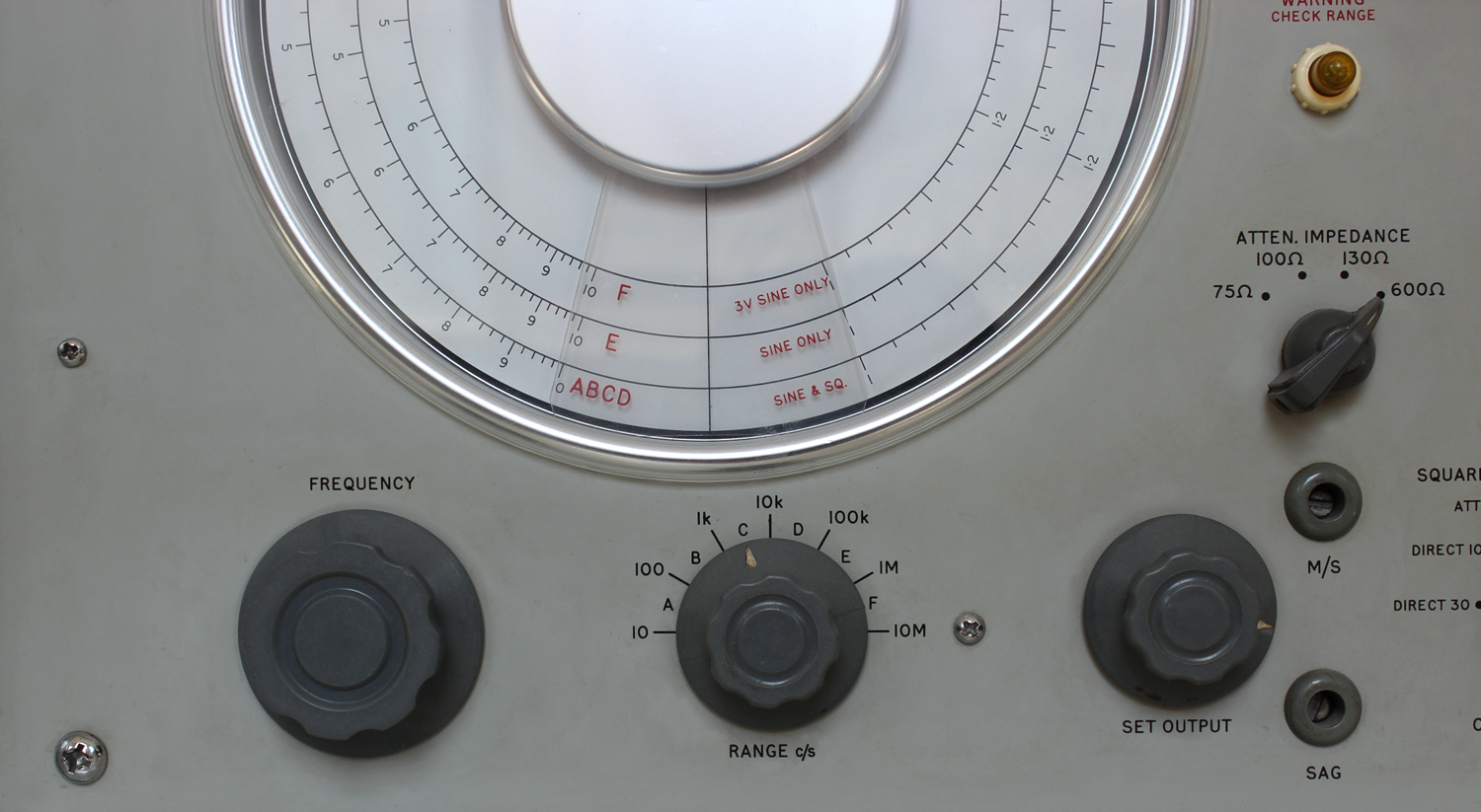
1.SUPPLY switch and indicator lamp.
2.RANGE selector. Letters refer to scales on the dial, and numbers indicate the scale extremes. Illustration shows setting for 1 kc/s.
3.FREQUENCY control. Combined two-ratio drive allowing quick coarse adjustment, then fine tuning over one turn of the knob.
4.FREQUENCY dial. Use scale indicated by setting of RANGE selector.
5.OUTPUT VOLTS selector. Selects sine wave or square wave operation, and output range at ATTEN or DIRECT output sockets. OFF position disconnects output without interrupting supplies.
6.SET OUTPUT control. Adjusts output voltage at ATTEN or DIRECT output sockets.
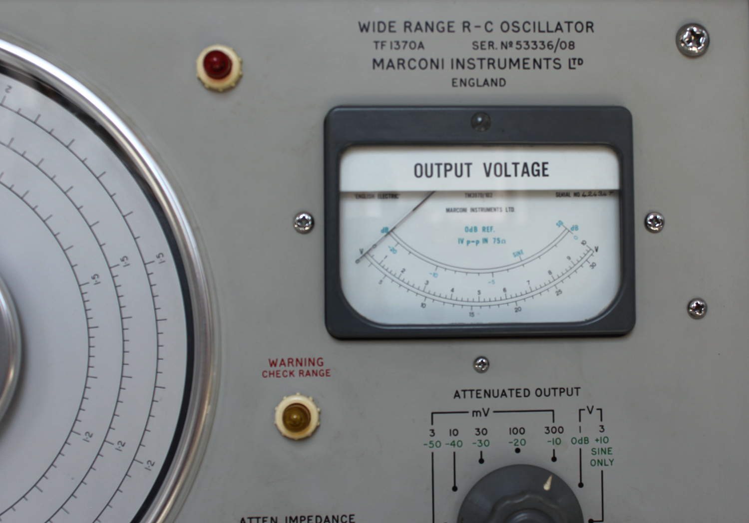
7.METER. Shows output at either ATTEN or DIRECT socket depending on settings of OUTPUT VOLTS SELECTOR and AT TENUATED OUTPUT switch. Indicates peak value of square waves and r. m. s. value of sine waves. SQ and SINE marks correspond to 1 V peak-to-pea.k in a. 75 Ω load.
8.ATTENUATED OUTPUT switch. Setting indicates full-scale meter deflection.
9.ATTEN IMPEDANCE switch. Indicates source impedance at ATTEN outputsocket on ‘mV’ settings of ATTENUATED OUTPUT switch. OFF position disconnects output without interrupting supplies.
10.ATTEN E.M.F. socket. Type ENC. For outputs up to 3.16 V. 11.DIRECT OUTPUT socket. Type BNC. For outputs up to 31.6 V. 12.WARNING CHECK RANGE lamp. Glows when an inadmissible combination of output range and frequency has been selected.
13.M/S preset. For fine adjustment of square wave mark] space ratio.
14.SAG preset. For zeroing square wave sag.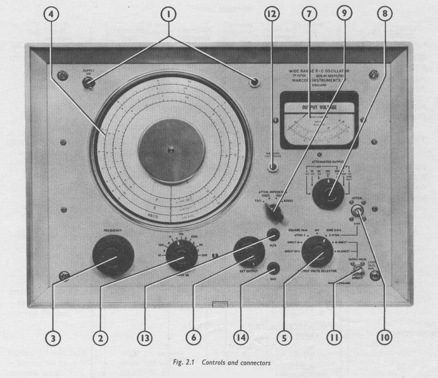
 2.5 ADJUSTING FREQUENCY
Turn the RANGE switch to select the frequency band and adjust the FREQUENCY tuning control for the required frequency.
The FREQUENCY tuning control has a combined two-ratio drive, allowing quick adjustment to approximately the required frequency, then fine tuning (over one turn of the knob) through the region of the required frequency.
2.6 SETTING OUTPUT VOLTAGE
Turn the OUTPUT VOLTS SELECTOR switch to the appropriate position for the output required. The settings of this switch for the various output conditions available are shown in Table 2.1.
Notes:
(i) If the OUTPUT VOLTS SELECTOR is set to any of the DIRECT positions and the RANGE selector is switched to above 1 Mc/s for sine waves, or above 100 kc/s for square waves, no output can be obtained. In this condition the WARNING CHECK RANGE lamp will glow.
(ii) The OFF position enables you to remove the output without switching off the supply or disconnecting the load.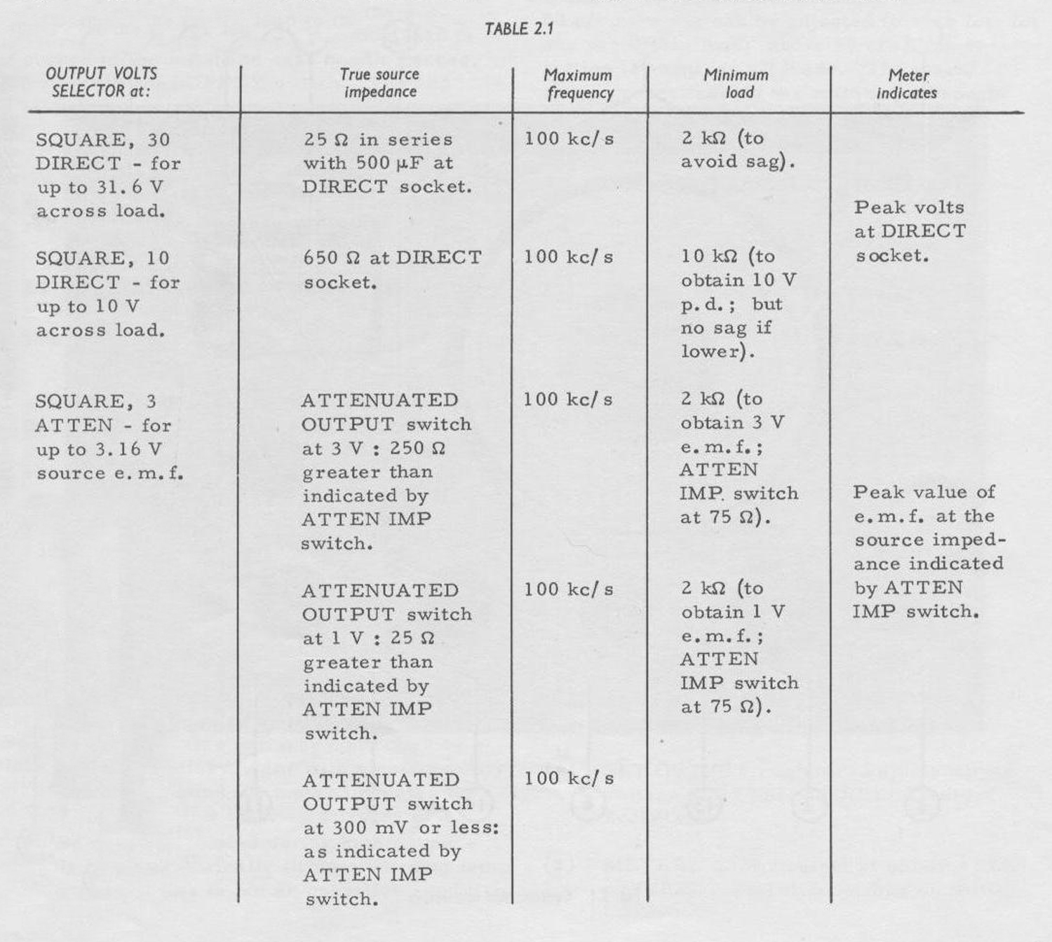 CAUTION
D.C. content in output. The output coupling capacitor in the R-C Oscillator is, of necessity, a high capacitance electrolytic type. This allows some cl.c leakage which may affect equipment connected to either outlet. The leakage voltage may amount to some 2% of the a. c. output, both at the DIRECT outlet when loaded with 2 kΩ, and at the ATTEN outlet when matched with 75 Ω .
Surges in output. When switching the SUPPLY on or off, and when turning the OUTPUT VOLTS SELECTOR, d.c. surges lasting several seconds arise at the outlets. Depending on the switching operation, the surge open circuit voltage may be up to about twenty times the a. c. output provided by the settings of the SELECTOR and ATTENUATED OUTPUT switches.
The output of the R-C Oscillator should be open or short circuited temporarily when the load is sensitive and might be damaged.
Direct output, up to 30 V
From the DIRECT output socket a sine wave or square wave of up to 10 V or up to 31.6 V can be obtained, depending on the position of the OUTPUT VOLTS SELECTOR and the SET OUTPUT control.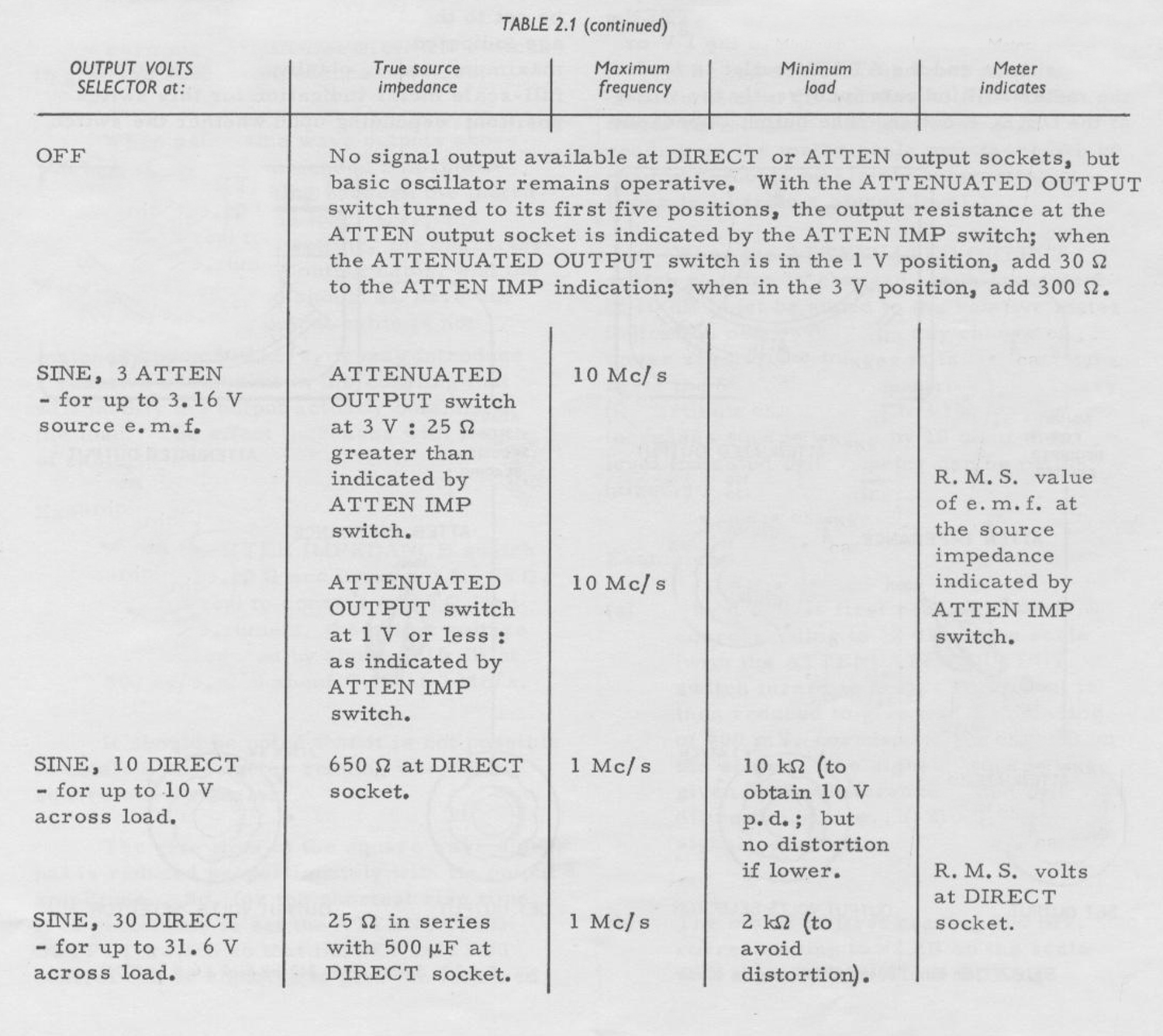 The meter, calibrated in peak values for square wave and r.m.s. for sine wave signals, indicates the voltage across the load at the DIRECT outlet; this voltage is adjusted by the SET OUTPUT control. The source impedance on the 10 V range is 650 Ω, and on the 30 V range it is 2.5 Ω in series with 500 µF. The permissible external loads are shown in Table 2.1.
As a rule, when a. square wave is taken from the DIRECT outlet, a short output cable should be used; a long cable may cause rounding of the square wave owing to loss of higher frequency components.
While the SELECTOR is at a DIRECT position output can be taken simultaneously from the ATTEN socket. But if the ATTENUATED OUTPUT switch is set to the 1 V or 3 V positions and the ATTEN outlet is loaded, the meter will indicate incorrectly the voltage at the DIRECT outlet. The output impedance at the ATTEN socket will be as for SQUARE ATTEN (see Table 2.1) for both sine and square waves.
Attenuated output, 0 to 3 V
When the OUTPUT VOLTS SELECTOR switch is turned to the SQUARE, 3 ATTEN or SINE, 3 ATTEN positions, the meter and the ATTENUATED OUTPUT switch together indicate the source e.m.f. , i. e. the open circuit voltage at the AT TEN output socket.
The seven position ATTENUATED OUTPUT switch provides one +10 dB and five -10 dB steps, relative to the 0 dB position. According to the voltage required, the ATTENUATED OUTPUT switch should be set to the appropriate position. The voltage indicated by each switch position is the maximum e.m.f. obtainable and also the full-scale meter indication for this switch position; depending upon whether the switch position figure commences with 1 or 3, the 10 V or 30 V scale of the meter should be referred to and the appropriate multiplying factor applied.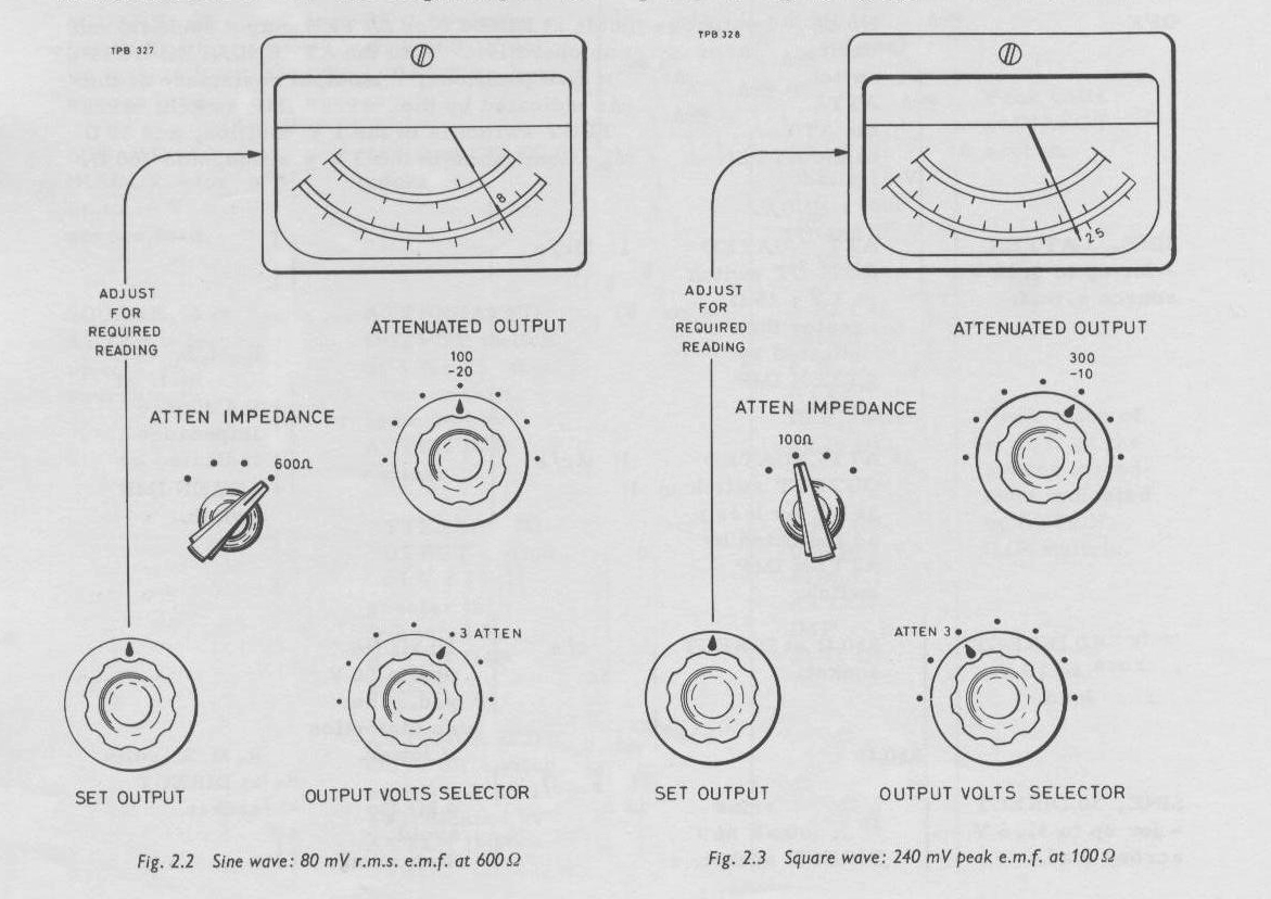 Examples:
(i) If 80 mV is required, turn the ATTENUATED OUTPUT switch to 100 mV, and adjust the SET OUTPUT control to obtain a reading of B on the 10 V meter scale.
(ii) If 240 mV is required, turn the ATTENUATED OUTPUT switch to 300 mV, and adjust the SET OUTPUT control to obtain a reading of 24 on the 30 V meter scale.
Turn the ATTEN IMPEDANCE switch to give the source impedance required.
When using sine wave outputs above 500 kc/s, it is recommended that there should be good matching between the instrument, output lead, and load, i. e., the ATTEN IMPEDANCE setting, the characteristic impedance of the output cable, and the impedance of the load should all have the same value. If the output cable is not matched above 500 kc/s, it may introduce a reactive component in the coupling that will modify the output actually obtained at the load. The effect increases with length of cable.
Example :
With the ATTEN IMPEDANCE switch turned to 600 Ω and using a 3 ft, 75 Ω, coaxial lead to connect a 600 Ω load to the instrument, the output voltage will be reduced by above 0.15 dB at 500 kc/s, and about 3 dB at 7 Mc/s.
It should be noted that it is not possible to obtain a zero meter reading when using square wave signals.
The rise time of the square wave signal is reduced proportionately with its output amplitude. So, for the shortest rise time, it is preferable to set the ATTENUATED OUTPUT switch so that the SET OUTPUT control can be adjusted to give the required output at a low meter reading. Further, to retain the shape of the square wave, try to obtain good matching between the instrument, output cable and load as recommended above for sine waves over 500 kc/s. (Note that the true source impedance is increased if the ATTENUATED OUTPUT switch is set to 1 V or 3 V — see Table 2.1.) If it is not convenient to obtain good matching, the output cable should be kept short; say 3 feet or less. Failure to match a longer cable may cause loss in the higher frequency components of the square wave and result in rounding of its shape. 2.7 dB READINGS
Reading relative dB levels
The top scale of the front panel meter is calibrated in dB relative to full-scale meter deflection. Changes of voltage reading on the meter scale may therefore be read in decibels by simply subtracting a lower level from a higher level.
When the ATTENUAT ED OUT PUT switch position is changed, each increment of 10 dB must be added to the relative meter indication obtained. Note any change of meter reading as the switch is turned, and reset the SET OUTPUT control if necessary (in particular, switching to +10 dB only increases square waves by 10 dB if the level indicated by the meter can be maintained.)
Examples:
(a) The meter is first reading 800 mV, corresponding to -2. dB on the scale (with the ATTENUATED OUTPUT switch turned to 1 V). The output is then reduced to give a meter reading of 400 mV, corresponding to -8 dB on the scale. The signal reduction is given by the difference between the two dB readings, i.e., (-2) – (-8) = 6 dB signal reduction.
(b) The meter is first reading 800 mV, corresponding to -2 dB on the scale with the ATTENUATED OUTPUT switch turned to 1 V. 0 dB. The output is then reduced to give a meter reading of 40 mV, corresponding to -8 dB on the scale, with the switch turned (through 20 dB) to 100 mV, – 20 dB. The signal reduction is given by the difference between the two dB indications, e. g. , (-2) – [(-20) + (-8)] = 26 dB.
Using standard video ref level
Included on the top scale of the front panel meter are two calibration marks, SQ and SINE, indicating the standard level of 1 V peak-to-peak in a. 75 Ω load (corresponding to 1 V peak e.m.f. at 75 Ω source impedance).
To obtain this level, set the ATTEN IMPEDANCE switch to 75 Ω, set the ATTENUATED OUTPUT switch to 0 dB (1 V), and adjust the SET OUTPUT control to obtain a meter deflection to the SQ or SINE mark on scale according to whether a square or a sine wave output is required from the ATTEN output socket. The standard level will then appear across the 75 Ω load.
If, for example, a signal 7 dB below the standard level is required, adjust the SET OUTPUT control to reduce the meter deflection by 7 dB as read on the meter dB scale (i. e. , down to -7 dB for a square wave output, or to -10 dB for a sine wave output).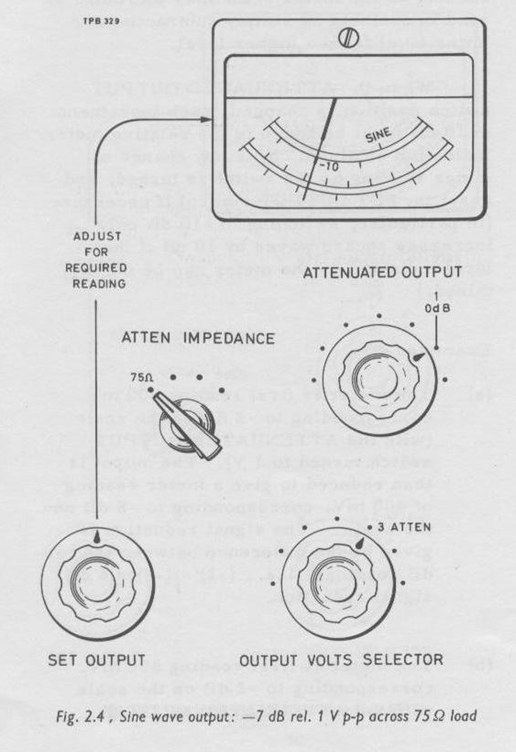
2.8 SETTING UP AUDIO STANDARD OUTPUT
If a sine wave source is required at the audio standard of 1 mW in 600 Ω, or levels at 10 dB or 20 dB above the standard, proceed as follows:
1 mW (0 dBm) in 600 Ω
(i) Connect the external equipment to the ATTEN output socket.
(ii) Turn the OUTPUT VOLTS SELECTOR switch to SINE, 3 ATTEN.
(iii) Turn the ATTEN IMPEDANCE switch to 600 Ω.
(iv) Turn the ATTENUATED OUTPUT switch to 3 V.
(v) Adjust the SET OUTPUT control to give a meter reading of 1. 55 V. (The meter indicates the e.m.f. at 600 Ω source impedance.)
10 mW (+10 dBm) in 600 Ω
(i) Connect the external equipment, via a 600 Ω resistor, to the DIRECT output socket.
(ii) Turn the OUTPUT VOLTS SELECTOR switch to SINE, so DIRECT.
(iii) Adjust the SET OUTPUT control to give a meter reading of 4.9 V. (The meter indicates the e.m.f. at 600 Ω source impedance.)
100 mW (+10 dBm) in 600 Ω
(i) Connect the external equipment, via a 600 Ω resistor, to the DIRECT output socket.
(ii) Turn the OUTPUT VOLTS SELECTOR switch to SINE, 30 DIRECT .
(iii) Adjust the SET OUTPUT control to give a meter reading of 15.5 V. (The meter indicates the e.m.f. at 600 Ω source impedance.)
Note : As the instrument load under these conditions is 1200 Ω, it is not advisable to obtain a meter reading greater than about 20 V, otherwise distortion will occur. The normal minimum load is 2 kΩ (see Table 2.1).
2.9 ADJUSTING SQUARE WAVE SAG AND MARK/SPACE RATIO
The SAG preset control on the front panel enables you to make readjustments, below about 100 c/s, to minimize the sag on the horizontal top and bottom of the square wave at any particular signal level and load conditions that comply with Table 2. l.
To make an adjustment proceed as follows:
(1) Connect the load to the instrument and set the controls to give the required signal output.
(2) Connect an oscilloscope, having a flat response down to d. c. and an input impedance that is large compared with the load, so as to monitor the square wave signal.
(3) Adjust the SAG preset control to give zero sag of the waveform viewed on the oscilloscope.
Note: At other conditions of load, frequency, and signal amplitude to those used above, there will be a. variation in performance, and the SAG control should be reset as described in section 4. 7. 2 in order to restore the instrument to the standard condition.
Mark/space ratio
The M/S preset control on the front panel enables you to readjust the mark/space ratio of the square wave signal to exactly 50/50 at a particular frequency.
To make an adjustment, proceed as follows:
(1) Set the controls of the instrument to give the required frequency.
(2) Connect an oscilloscope, having a response that is flat from d. c. to 1 Mc/s, so as to monitor the output signal.
(3) Adjust the M/S preset control to give exactly the required mark space ratio of the square wave, viewed on the oscilloscope.
Note : To restore the instrument to the standard condition, see section 4. 7. 1. 2.10 USE OF ACCESSORIES
Unbalanced-to-Balanced Transformer Type TM 6221
The transformer is for use with sine wave signals between 10 c/s and 100 kc/s, fed from a 600 Ω source. It provides balanced outputs at an impedance of 150, 200, and 600 Ω and has a centre-tapped secondary winding.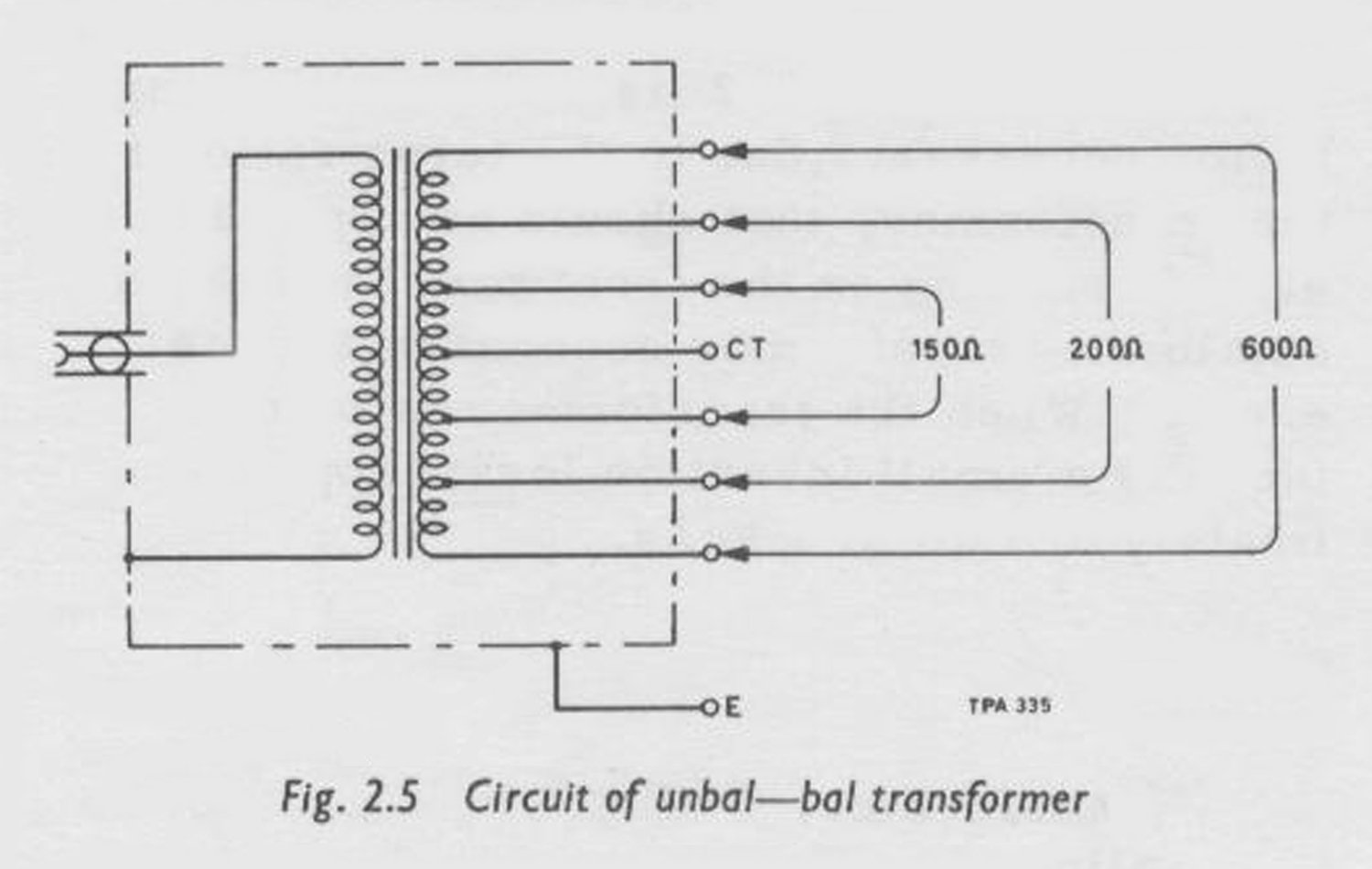 An output may be taken from one half of the various secondary windings, i. e. , from one terminal of a pair and the centre tap. In these cases, the output impedance will be one quarter of the impedance marked at a particular terminal. The high frequency response may be slightly worsened.
Example :
If an output is taken from one 200 Ω terminal and the C. T. terminal, the
output impedance will be 50 Ω – or if taken from one 150 Ω terminal and the C. T. terminal, the output impedance will be 37.5 Ω.
Connect the transformer input socket to the TF 1370A ATTEN output socket, by means of a coaxial lead fitted with BNC type plugs (e.g. , TM 4726/136), and connect the external load to the appropriate terminals on the transformer. Turn the ATTEN IMPEDANCE switch to 600 Ω, the OUTPUT VOLTS SELECTOR switch to SINE, 3 ATTEN, and adjust the oscillator and the output voltage as described in sections 2.5 and 2.6.
The centre tap of the secondary winding on the transformer may be connected to its earthed terminal to obtain an output that is balanced with respect to earth, or, if this connection is not made, an output may be obtained that is floating or at some d. c. potential with respect to earth; the maximum d. c. potential allowable between the primary and the secondary windings is 200 V.
The secondary source e.m.f. between the 600 Ω terminals is the same as the e.m.f. indicated by the TF 1370A. For other output impedances Table 2. 2 lists the multiplying factor necessary, due to the turns ratio of the transformer, that should he applied to the e.m.f. reading on the front panel meter to obtain the transformer secondary source e.m.f. When the transformer is loaded there is a small insertion loss; approximately 0.5 dB at 1 kc/s.
CAUTION
It is important that d. c. should not be allowed to flow in the windings of the transformer.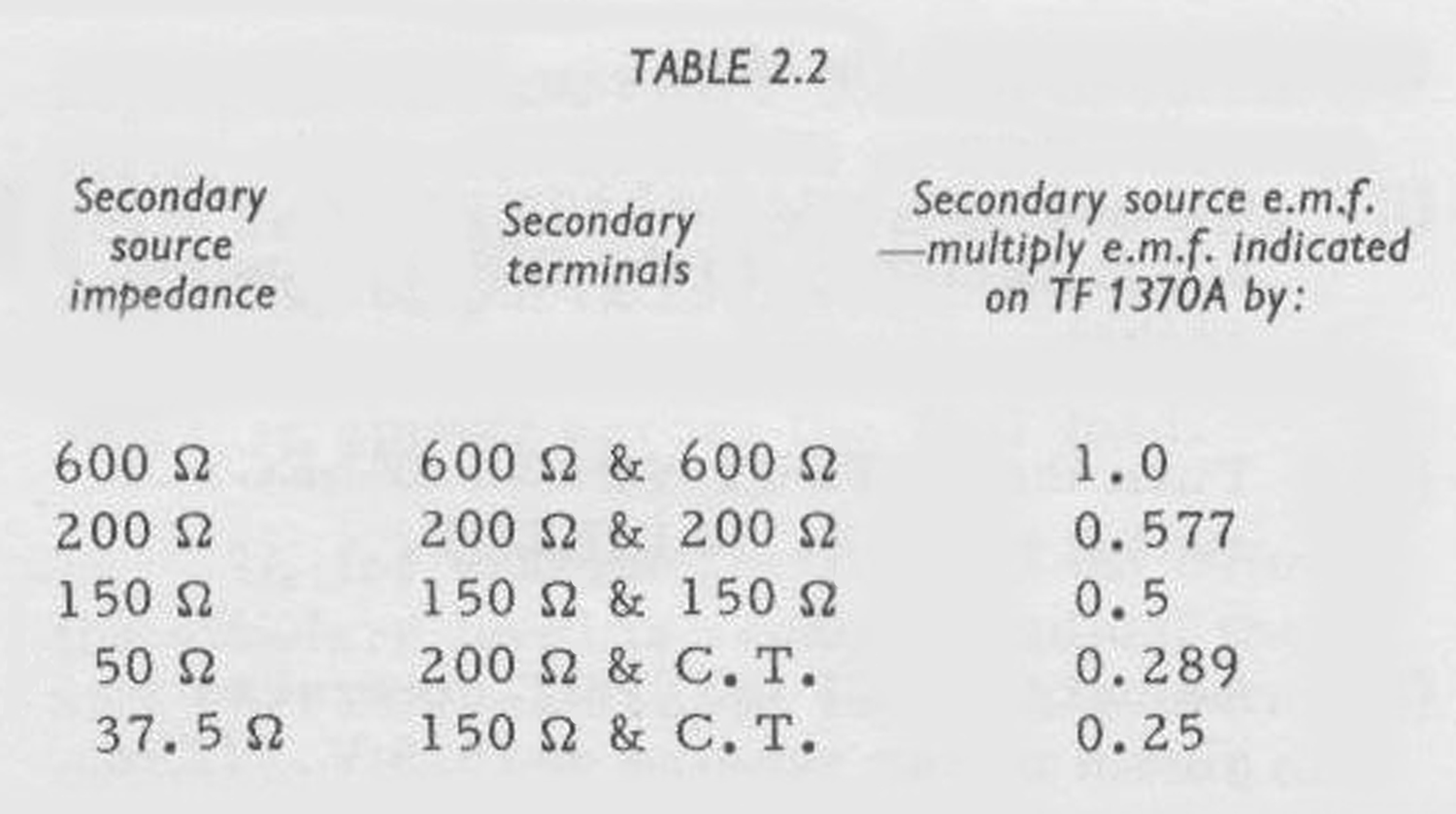
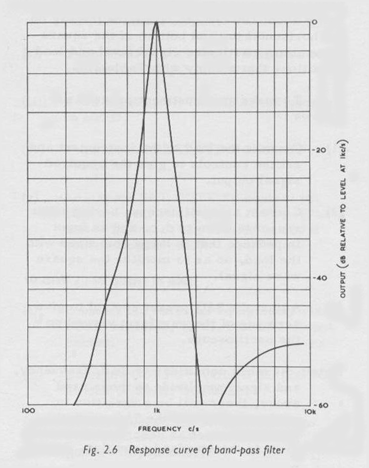 1 kc/s Band-Pass Filter Type TM 6222
The 1 kc/s Band-Pass Filter is for use with the TF 1370A to give very pure outputs of 1 kc/s sine wave signals at a source impedance of 600 Ω.
Connect the Band-Pass Filter input socket to the TF 1370A ATTEN output socket by means of a. coaxial lead fitted with BNC type plugs, and the two terminals on the Band-Pass Filter to the external load. Turn the ATTEN IMPEDANCE switch to 600 Ω, and the OUTPUT VOLTS SELECTOR switch to SINE, 3 ATTEN. Adjust the oscillator frequency to 1 kc/s and the output voltage to the required amplitude as described in sections 2, 5 and 2. 6 respectively. If a valve voltmeter is available, this should he connected across the load and the oscillator frequency adjusted for maximum valve voltmeter reading.
Assuming that the load is 600 Ω, a signal voltage measured across the load will be about 10% below half the e.m.f. indicated by the front panel meter. To ascertain the exact signal voltage across the load, proceed as follows:
(i) Turn the ATTENUATED OUTPUT switch to 3 V .
(ii) Adjust the SET OUTPUT control to give 3 V meter deflection.
(iii) Connect a valve voltmeter, set to read 1. 5 V, across the load and read the exact voltage.
(iv) The difference between the TF 1370A e.m.f. reading and the valve voltmeter reading, expressed as a ratio, may then be used to determine accurately the voltage across the same load at other, lower, levels.
The filter can be used with the ATTEN IMPEDANCE switch turned to 75 Ω, 100 Ω or 130 Ω, if some worsening of the second harmonic content and a larger insertion loss is acceptable.
Note: The filter should never be used without a terminating load.
×100 Attenuator Pad Type TM 6454
The ×100 Attenuator Pad matches the 75 Ω source impedance of the ATTEN output socket on the TF 1370A, and it is suitable for use with sine wave and square wave signals at all frequencies within the operating range of the instrument.
The Attenuator Pad has a BNC INPUT socket and two BNC OUTPUT sockets both giving 100 times e.m.f. attenuation. The input impedance is 75 Ω; the source impedance at one output socket is 75 Ω and at the other it is 5 Ω.
If, for any particular application, a 5 Ω source impedance is required with less attenuation, then the signal from the TF 1370A may be fed into the 75 Ω OUTPUT socket of the Attenuator Pad and the external load connected to the 5 Ω OUTPUT socket.
Under these circumstances the e.m.f. attenuation will be 30 times.
Note: The TF 1370A is not a fully screened signal generator and consequently errors in the signal level, due to
leakage, may occur at µV signal levels at the highest frequencies».
§§§
Il testo prosegue, come si legge all’inizio, nella scheda dedicata al Wide Range R-C Oscillator TF 1370°, Serial N° 54110/053. Marconi Instruments Ltd. England.
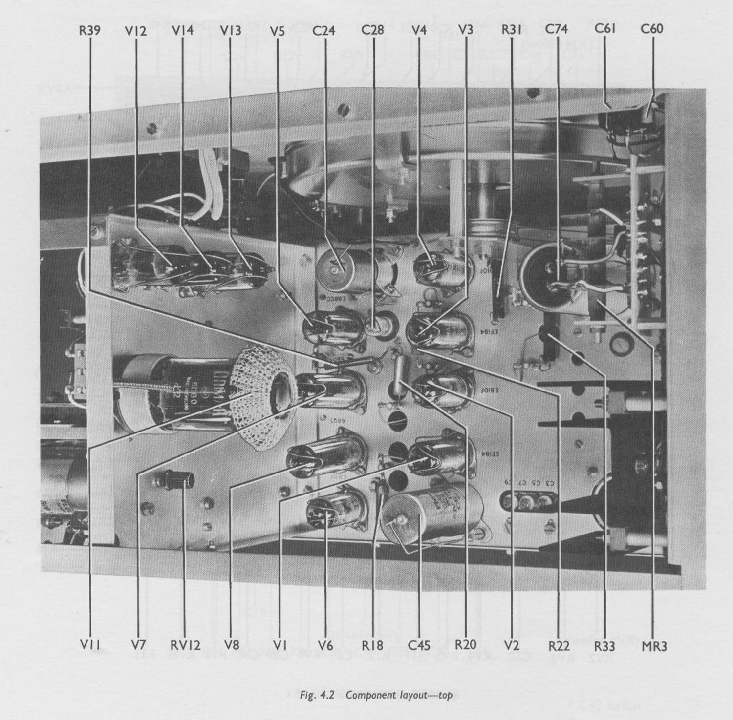
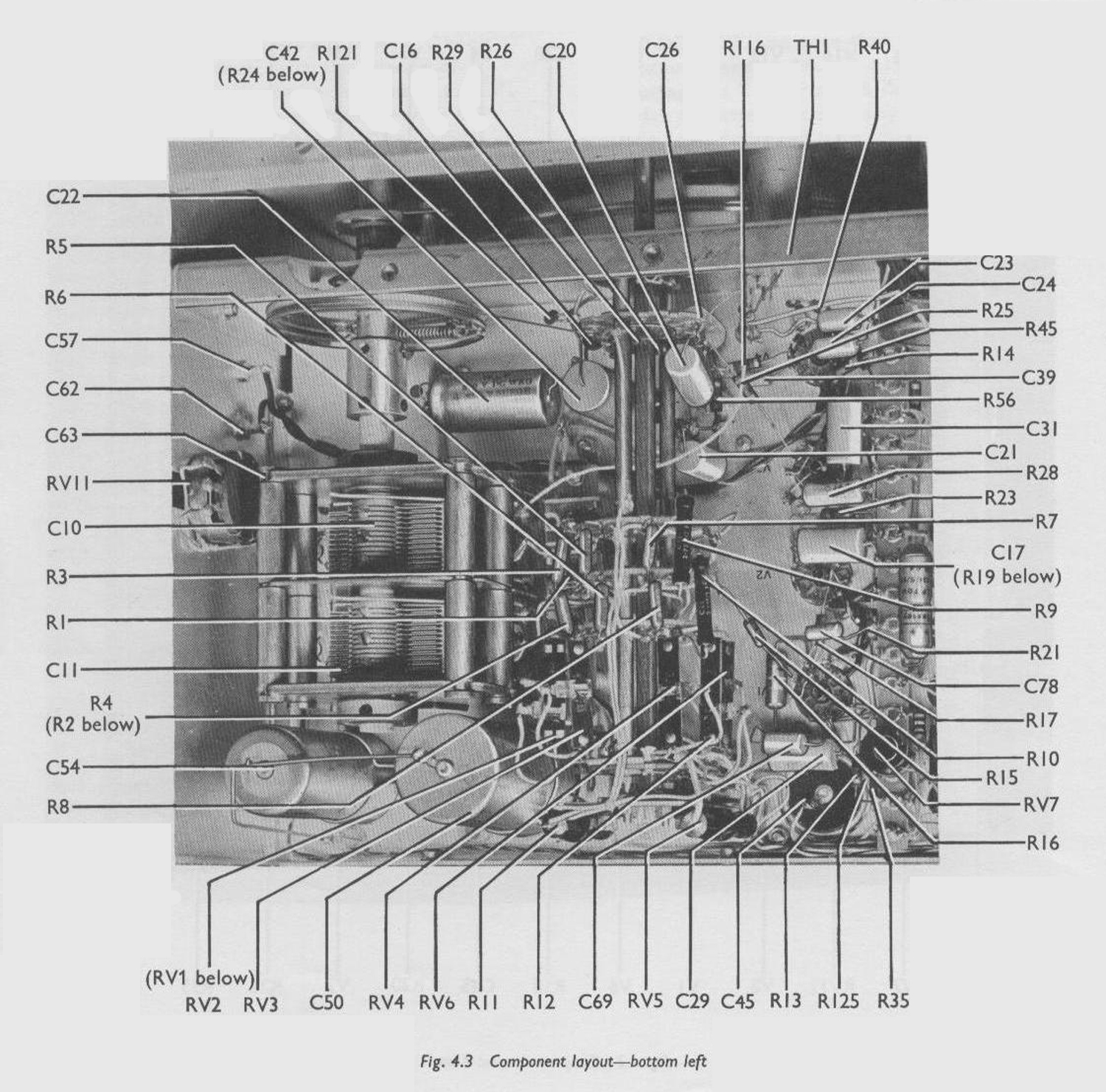
Abbiamo omesso il capitolo “Maintenance” del quale abbiamo scelto alcune figure.
Foto di Claudio Profumieri, elaborazioni e ricerche di Fabio Panfili. Testo a cura di Fabio Panfili.
Per ingrandire le immagini cliccare su di esse col tasto destro del mouse e scegliere tra le opzioni.