Oscilloscopio Tektronix Type 565. Ottava parte.
Nell’inventario D del 1956 si trova al n° 3747 e risulta acquistato nell’agosto del 1964; vi si legge: “Silvestar ltd. Milano. Oscilloscopio Tektronix mod. 565 matr 689. Dest. Elettronica ₤ 1·678·600”. Insieme alla fotocamera che è al n° 3746, dove si legge: “Silvestar ltd. Milano. Macchina fotografica Tektronix mod. C-12 completa di Bezel-Tektronix. Dest. Elettronica. ₤ 557·700”.
Il testo continua dalla settima parte.
§§§
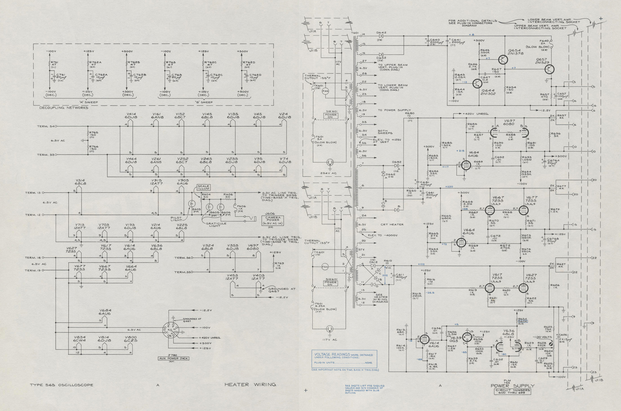
«LOW VOLTAGE POWER SUPPLIES
General
The Low Voltage Power Supplies consist of four
interdependent, regulated voltage sources. Each supply is
capable of maintaining an accurate dc output voltage
having a low percentage of ripple, even though the
input line voltage and the output load may vary considerably.
-100 Volt Supply
When the design-center voltage is applied to the primary
of T601, the voltage across secondary terminals 6 and 11 is
about 145 volts rms. This voltage is applied to a conventional full-wave bridge rectifier, D612, producing about 200 volts dc across filter capacitor C611. This voltage is then divided between the load and the series regulator tubes.
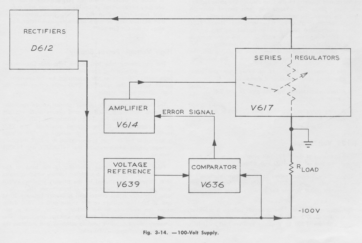
The block diagram Fig. 3-14 shows the basic elements of the circuit which accomplish this division.
The regulator tubes function as a variable resistor in
series with the load. In order to maintain a stable voltage
across the load, their plate resistance must be changed as
required to offset the effect of a change in line voltage or
load current. To accomplish this, the output voltage is
constantly compared to a fixed reference voltage by the
comparator V636. Any error thus detected is amplified and
applied to the series regulators. Their plate resistance is
thereby changed and the proper output voltage is restored.
Refer to the Power Supply schematic in the back of this
manual. The voltage reference tube V639 applies a stable
-85 volts to the ‘A’ grid of a long-tailed difference amplifier
V636. This establishes an essentially constant voltage at the
common cathodes of both V636A and V636B. A sample of
the supply output voltage is obtained from the -100 VOLTS
control, R624. (This sample will always be about -85 volts,
since it is the voltage actually being regulated to match the
reference voltage. Since the -100 VOLTS control is set so
the sample is 85% of the total voltage across R623, R624 and R625, the total voltage will also be regulated.) If a positive-going change occurs in the output voltage, the grid voltage on V636B changes in the positive direction. The current through V636B increases and its plate voltage drops. This negative-going voltage change is applied to the control grid of amplifier V614. The current through V614 decreases and its plate voltage rises, carrying the grids of V617 and V627 positive. The regulator tubes’ plate resistance decreases, therefore increasing the current through the load.
This results in an increased voltage drop across the load, thus offsetting the error.
Negative-going changes are corrected in the same way
except for error signal polarities. Due to the high gain of the
amplifier circuits and their ability to respond quickly, the
supply in effect corrects for changing line voltage and load
conditions before a significant change can occur in the
output voltage.
The dc voltage across C611 bears a substantial amount
of ripple. A sample of this ripple is applied to the screen
grid of V614. The screen grid acts as a second signal grid
and aids in eliminating much of the ripple from the supply
output. C636 and C629 also aid in eliminating ripple since
they offer less attenuation to ac error signals than do the
resistive voltage dividers. C626 lowers the supply output
impedance.
R626 and R627 are particularly important elements in
the -100 volt supply. It would be impractical to pass all
of the current required by the load through the series
regulator tubes. Since line voltage and load current variationlimits are known, the series regulator tubes
need only carry enough current to allow for these variations. Hence, R626 carries a substantial amount of the current required by the circuits within the Type 565. R627 serves the same purpose for each of the vertical plug-in units. Depending on the amount of current required by each type of plug-in unit, the connections within the plug-in will be one of the following:
1.No connection to pin 22 of the plug-in unit
interconnecting plug (low current demand).
2.A resistor connected between pins 22 and 9 (moderate
current demand).
3.A wire connected between pins 22 and 9 (maximum
current demand).
+125 Volt Supply
The operation of the +125 volt supply is similar, in most
respects, to that of the -100 volt supply.
The -100 volt supply serves as the voltage reference for
the +125 volt supply. R673 and R674 are the principle
circuit elements that determine the accuracy of the output
voltage.
Full-wove rectification of the ac supply voltage is provided
by rectifiers D662A and D662B. These two diodes are
shared with the +300 volts supply to form half of a full-
wave bridge.
+300 Volt Supply
The only significant difference between the +125 and
+300 volt supplies is the +420 volt unregulated output
associated with the +300 volt supply. This voltage is used
in the oscillator portion of the Crt Circuit.
-12.2 Volt Supply
R643 and R644 provide the reference voltage at the base
of Q644. Any voltage error at the emitter of Q644 is
amplified, but not inverted, and applied to the base of Q654.
Q654 amplifies and inverts the error signal, providing the
necessary drive for the series regulator Q657. C647 and
R647 provide phase correction for Q654, thereby stabilizing
the regulator.
The -12.2 volt supply does not employ shunt resistors
as do the other three supplies. Instead, all load current
passes through the series regulator. Fuse F640 protects
Q657 from overload. C657 reduces the supply output
impedance.
CRT CIRCUIT
CAUTION
Always make or break voltmeter connections at
any of the high-voltage points in the Crt Circuit
(except for the HIGH VOLTAGE TEST POINT)
while the instrument is turned off. If a connection
is made or broken while the power is on, a small
arc may occur which will produce voltage and
current transients within the circuit. Such transients
can destroy one or more of the semiconductor
devices in the Crt Circuit.
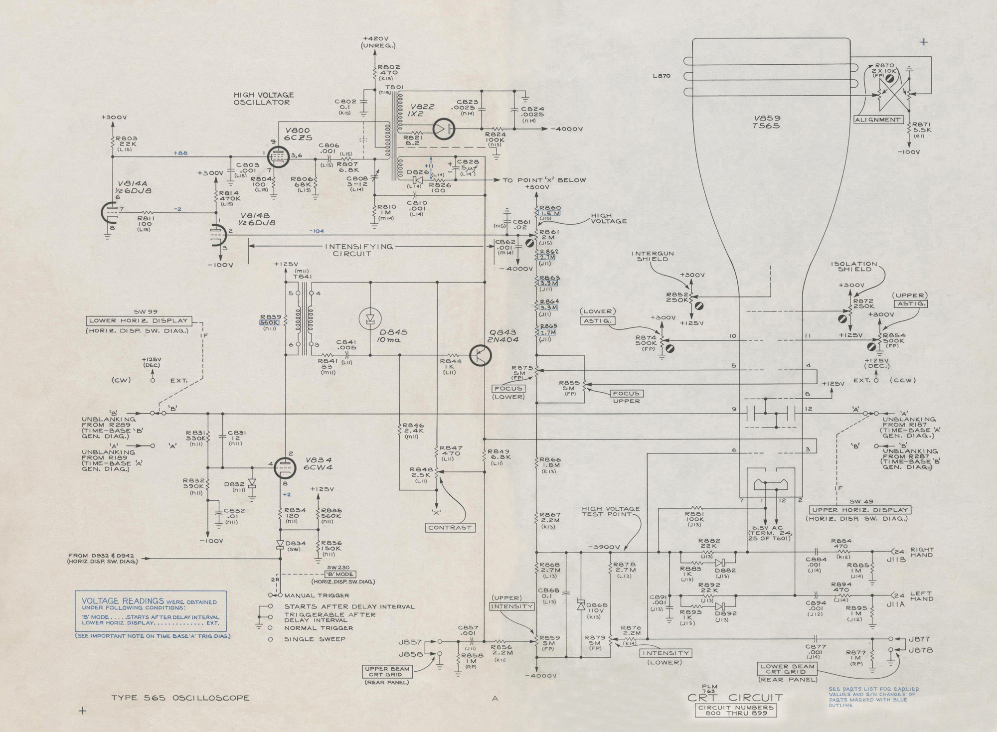
High Voltage Power Supply
The cathode-ray tube (crt) in the Type 565 Oscilloscope
requires an accelerating potential of about 4100 volts.
Approximately 200 volts of this is supplied by the low-voltage power supply. The remaining 3900 volts comes from the high-voltage power supply.
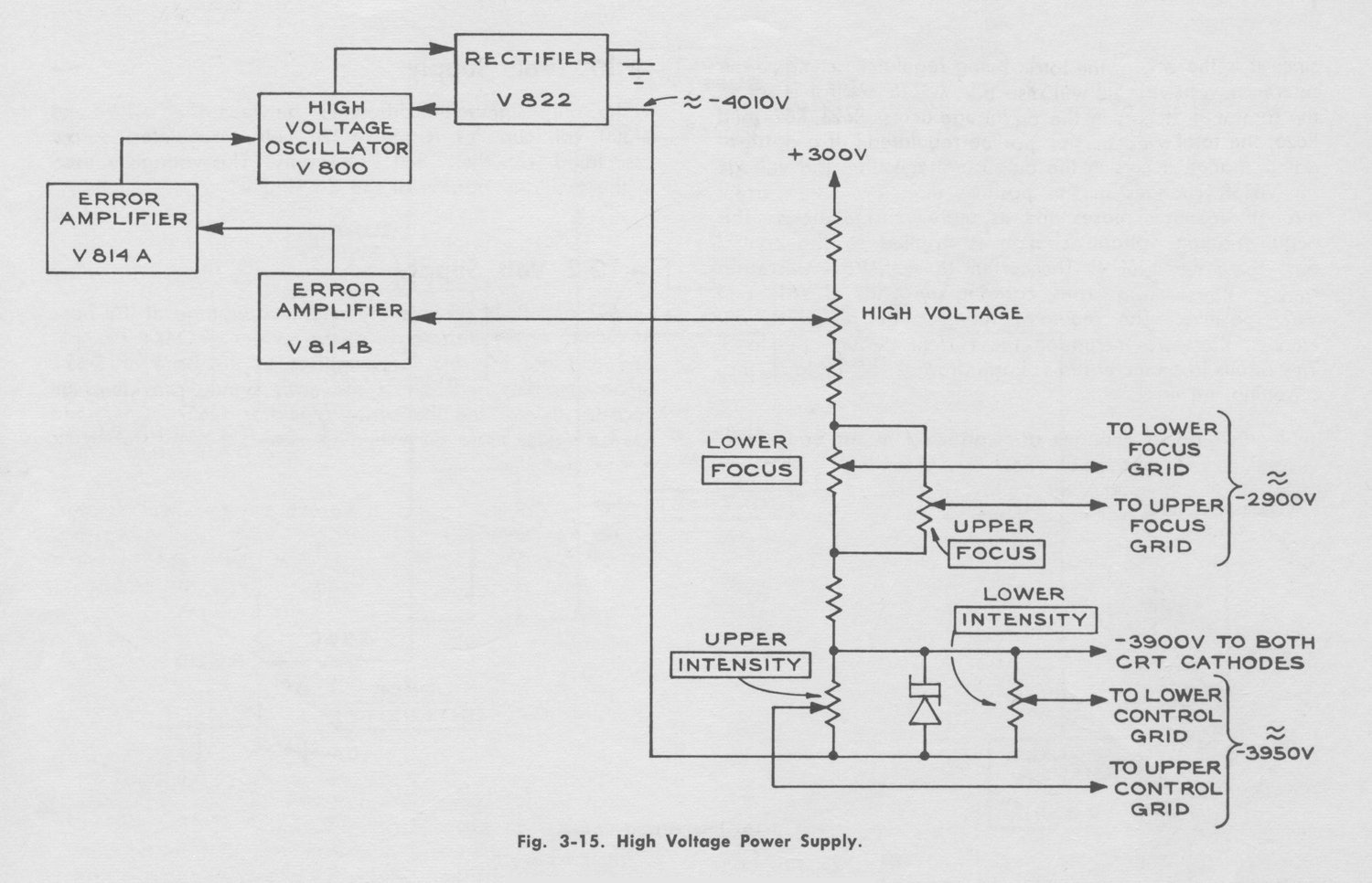
The high-voltage power supply consists of an oscillator,
a step-up transformer, rectifiers, and circuits which regulate
the high voltage (see Fig. 3-15). Transformer T801 steps up
the oscillator signal to the required amplitude, and V822
rectifies the signal, producing high voltage dc. This voltage
is applied to the crt from several points in a high resistance
voltage divider which includes the INTENSITY and FOCUS controls.
Refer to the Crt Circuit schematic in the back of this
manual. The oscillator is a modified Hartley which operates
at a frequency determined by the primary winding inductance and inter-turn capacitance of transformer T801. Oscillator frequency is not critical and is usually between 30 kc and 50 kc. The voltage on the screen grid of V800
determines the amplitude of the oscillator signal, which in turn determines the value of dc high voltage produced. This
property of the circuit is used to establish and maintain the
correct high voltage; -3900 volts.
The high voltage is applied to a high resistance voltage
divider which includes the INTENSITY, FOCUS, and HIGH VOLTAGE controls. With any particular setting of the HIGH VOLTAGE control, a certain percentage of the total voltage across the voltage divider is applied to the grid
of V814B. This grid voltage will always be about -103.5
volts, since it is the voltage actually being regulated. Since
the grid voltage is regulated and is a known fraction of the
high voltage, the high voltage will also be regulated.
When the voltage at the grid of V814B is -103.5 volts,
the voltage at the plate of V814B and the grid of V814A
will be about -2 volts. The voltage at the plate of V814A
and at the screen of V800 will be about +90 volts. If the
high voltage should change, the voltage at the grid of
V814B will also change. This change will be amplified by
V814B and V814A, thus changing the voltage on the screen
of V800. If, for example, the screen voltage is made more
positive, the oscillator signal amplitude will increase and
a greater dc high voltage will be produced.
Due to C862, the high gain of the error amplifier, and
the ability of the circuit to respond quickly, there is rarely
any significant variation in the high voltage. This is
because the correction for any change begins at nearly the
same instant as the change. Thus, a change is stopped
and corrected before it can become more significant.
Intensifying Circuit
The intensifying Circuit operates only when the TRIGGERABLE AFTER DELAY INTERVAL and STARTS AFTER DELAY INTERVAL modes of Time Base ‘B’ are used. Its only function is to dc couple a positive-going pulse to the upper beam CRT control grid. The normal voltage on this grid is about -3975 volts. The positive-going pulse at the control grid will cause a brightened segment within the upper beam trace.
(For more information about the purpose of the brightened trace segment, see “Using the ‘B’ MODE Switch” in Section 2 of this manual.)
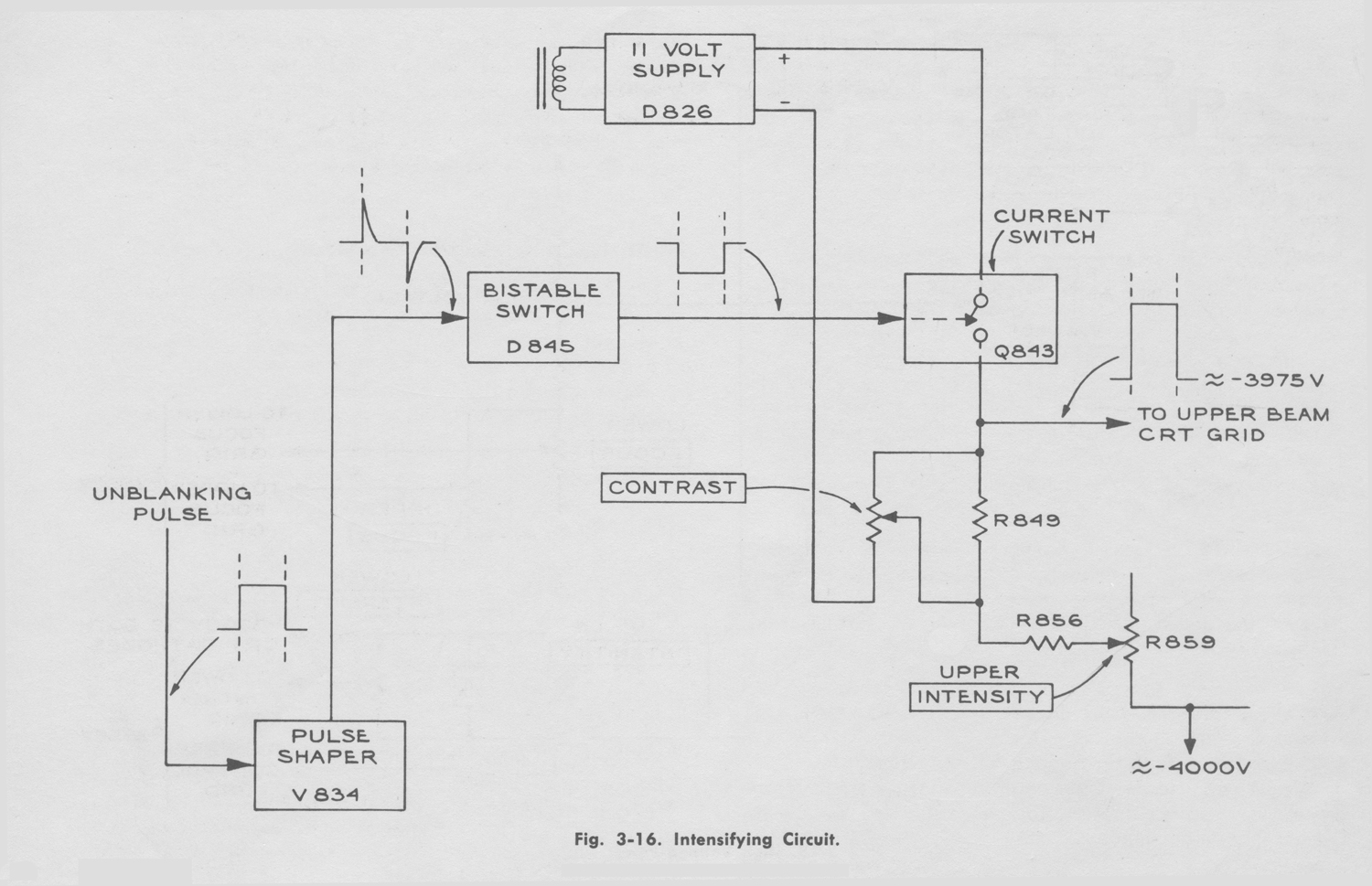
The basic elements of the intensifying Circuit are shown
in Fig. 3-16. Pulse Shaper V834 converts the applied
unblanking pulse into alternate positive and negative voltage pulses. These pulses actuate the bistable tunnel-diode switch D845 to produce a negative-going turn-on pulse for Current Switch Q843.
When the Current Switch Q843 is open, the floating 11volt
supply does not produce a voltage drop across R849.
The voltage on the upper beam crt control grid during
this time depends entirely upon the setting of the INTENSITY control. However, when the Current Switch is closed, current through R849 produces a voltage drop that drives the crt grid more positive. This causes a portion of the upper beam trace to be brightened.
For the following portion of the circuit description, refer
to the Crt Circuit schematic in the back of this manual.
The LOWER HORIZ. DISPLAY switch provides a choice
between three signal sources for unblanking the crt: ‘A’
Unblanking, ‘B’ Unblanking, or +125 volts dc. Each of
these signals can cause the intensifying Circuit to operate.
However, only the ‘B’ Unblanking signal will cause the
Intensifying Circuit to produce an intensified crt display.
Hence, the following description assumes the use of the
‘B’ Unblanking signal.
If Time Base ‘B’ is not generating a sweep, the CRT
unblanking voltage from the LOWER HORIZ. DISPLAY switch is about +25 volts and V834 is cutoff. When Time Base ‘B’ is then triggered, the unblanking voltage switches sharply to about +125 volts and V834 conducts heavily. (It is important to note that the circuit operates only with the ‘B’ MODE switch in the STARTS AFTER DELAY INTERVAL or TRIGGERABLE AFTER DELAY INTERVAL position to provide cathode current for V834.) The sudden surge of current through T841 produces a sharp pulse in the secondary circuit.
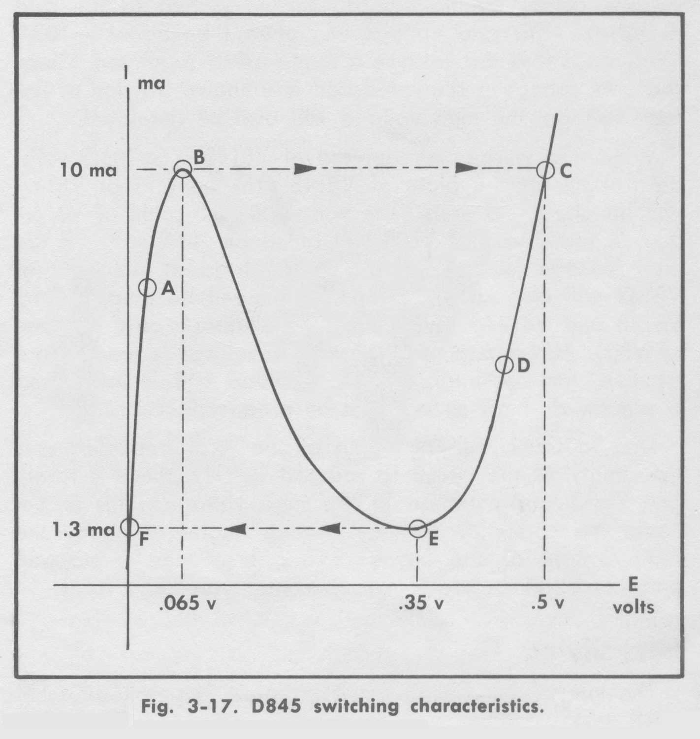
The dynamic characteristics of tunnel diode D845 are
shown in Fig. 3-17. Prior to the arrival of the pulse, the
tunnel diode maintains stable forward conduction at point
A on the curve. The voltage across the diode is then about
40 millivolts. This voltage is applied to the base-emitter
junction of Q843, but is not sufficient to cause the transistor
to conduct. Since there is no current through Q843, there
is no voltage drop across R849 and the voltage on the
upper beam crt control grid depends only on the setting
of the INTENSITY control (usually about -3975 volts at
normal trace brightness).
When the pulse is produced in the secondary circuit of
T841, the diode is driven through point B on the curve. The
diode is unstable at point B and therefore switches rapidly
to point C. As the input pulse subsides, the diode is unable
to continue operation at point C because R846 cannot satisfy the diode’s simultaneous demands for heavy current and high state voltage. Current then diminishes and the diode assumes stable operation at point D.
With the voltage across the diode now about 400
millivolts, Q843 is turned on. The current path is from the
positive end of C828, through Q843, R349, to the CONTRAST control (R848), and to the negative end of C828. The voltage drop thus produced across R849 drives the upper beam crt control grid several volts in the positive direction. This causes an increase in crt beam current and the trace becomes brighter.
When the unblanking pulse ends, V834 is suddenly cutoff,
producing a pulse in the secondary circuit with polarity
opposite that of the previous pulse. The tunnel diode is
driven from operating point D (Fig. 3-17) through point E.
The diode is unstable at point E, and therefore switches
rapidly to point F. At this point, R846 cannot satisfy the
diode’s demand for both low current and low state voltage.
Therefore, the current increases and the tunnel diode resumes stable operation at point A. The transistor reverts to cutoff, the upper beam crt control grid voltage drops to its
previous, more negative value, and the trace dims.
The CONTRAST control provides a means of controlling
the amplitude of the intensifying pulse and therefore the
amount of brightness increases during the brightened
segment of the upper beam trace. This is accomplished in the following manner.
As is true with most switches, transistor Q843 has a very
high series resistance when turned off and a very low series
resistance when turned on. Therefore, nearly all of the
11-volt supply voltage is dropped across R849 when Q843
is turned off. Hence, by controlling the total voltage
across the transistor and resistor, it is possible to control
the output pulse amplitude.
The CONTRAST control R848 and R847 form a voltage
divider across the 11-volt supply. By turning the CONTRAST control, the operator can vary the voltage across Q843 and R849 between about 2 and 11 volts.
Unblanking
A trace or spot can be obtained on the crt at all times
when an external signal is used for horizontal deflection.
However, such is not the case when horizontal deflection
is provided by one of the time base generators. When the
oscilloscope is used in the latter manner, a blanking signal
from the time base generator is applied to the crt. This
signal turns off the beam during sweep retrace and holds
it off until the next sweep begins.
Each of the two crt electron guns has a deflection plate
blanking system. A pair of deflection plates, similar to
those used for vertical and horizontal deflection, is placed
between the control and focus grids in each gun. One
plate in each pair is permanently connected to the +125
volt supply. The second plate can be connected to the
+125 volt supply or to one of the time base generators,
depending on the setting of the horizontal display switches.
The beam is constantly unblanked when the +125 volt
(EXT.) switch position is used.
If one of the time base generators provides horizontal
deflection for a particular beam, that beam will be
alternately blanked and unblanked in the following manner:
Between sweeps, the voltage applied to the crt blanking
plate by the time base generator will be about +25 to +30
volts With the other plate at +125 volts, the beam is
drawn into and absorbed by the more positive plate. Little
or no beam current gets past this point. When the time
base generator begins a sweep, it quickly increases the
voltage on the blanking plate to about +125 volts. Since
the blanking plate potentials are then essentially equal, the
beam current is released and passes on toward the face of
the crt to produce light.
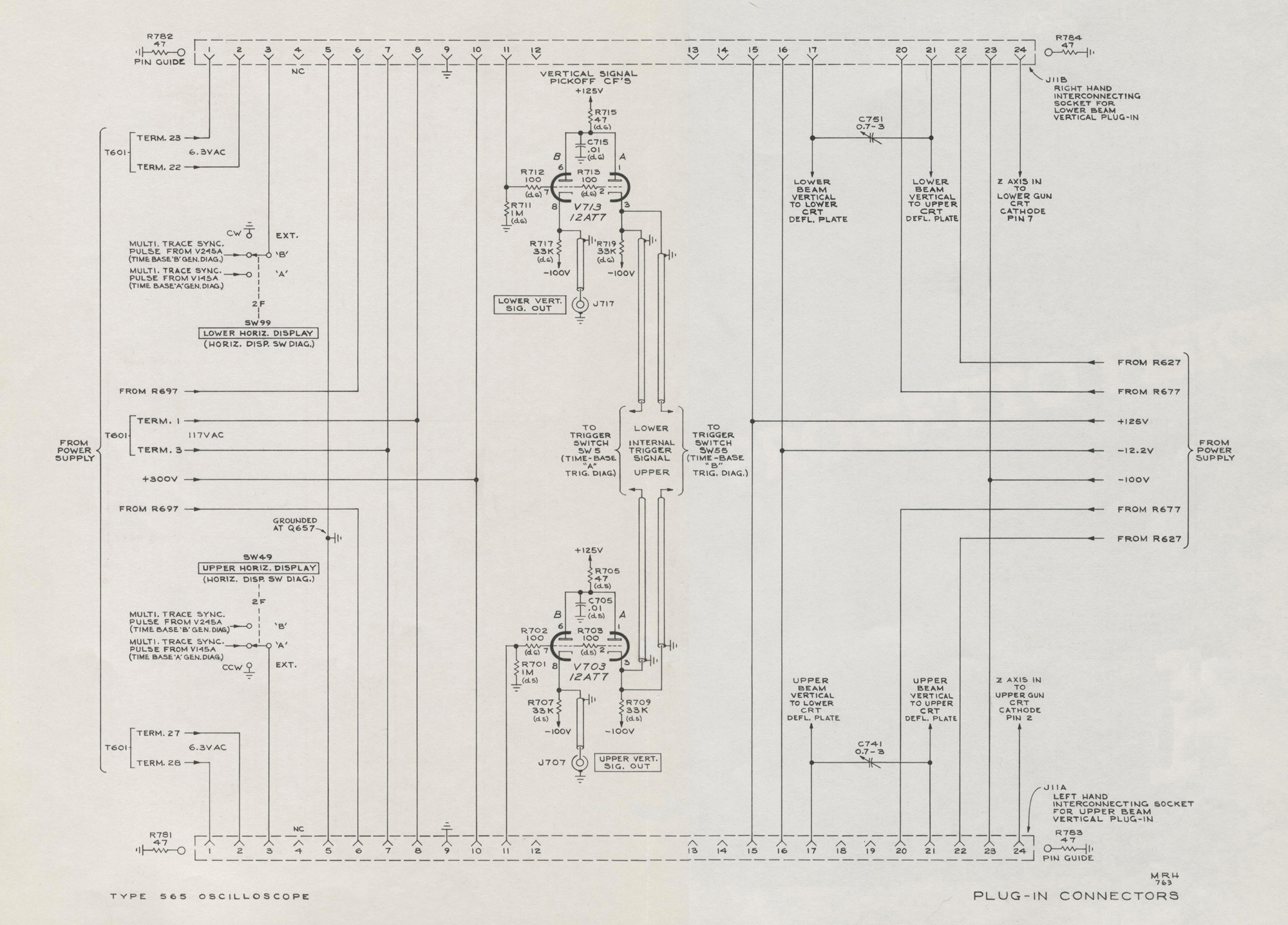
Multi-trace Chopped Blanking
The Type 565 Oscilloscope can be used with multi-trace
plug-in units such as the Type 3A74. When this type of
plug-in unit is operated in the “chopped” mode, the
display may consist of up to four traces per beam. The plug-in forms the display by switching on each information-
channel, one at a time, in a rapidly repeating sequence.
The vertical signal information available at the output
of the plug-in during the very short time required to switch
channels, is of no value in the display. Hence, this information is blanked out.
A pulse from the plug-in unit is available at pin 24 of
the plug-in interconnecting jack when switching from one
channel to the next. This pulse is coupled through a dc
blocking capacitor to the appropriate crt cathode. The
pulse momentarily drives the cathode positive and cuts off
the beam current until the plug-in has finished switching
to the next channel.
Diodes D892 and D882 are dc restorers. They insure
equal trace brightness for the chopped and conventional
mode. They permit the crt cathodes to be driven positive
by the incoming signal, but prevent the cathodes from being
driven more negative than the voltage at the HIGH VOLTAGE TEST POINT; -3900 volts.
Intergun Shield and Isolation Shield
Proper adjustment of the INTERGUN SHIELD and ISOLATION SHIELD controls insures that (1) a straight line display will appear as a straight line, regardless of its position on the screen, and that (2) a display which is well focused at the center of the screen will also exhibit good focus at the edge of the screen. These controls also affect the deflection sensitivity and scan limits of the crt.
Trace Alignment
The trace alignment coil surrounds the crt at a point
about 6 inches behind the face plate. The plane of the
coil is parallel to the plane of the face plate. The TRACE
ALIGNMENT control determines the amount and direction
of the dc current through the coil. By adjusting this control,
the entire display can be rotated a few degrees clockwise
or counterclockwise about the axis of the crt.
Display alignment is affected by the earth’s magnetic
field and may change when the instrument is moved. In
such cases, the operator can quickly realign the display
with the graticule markings by adjusting the TRACE
ALIGNMENT control.
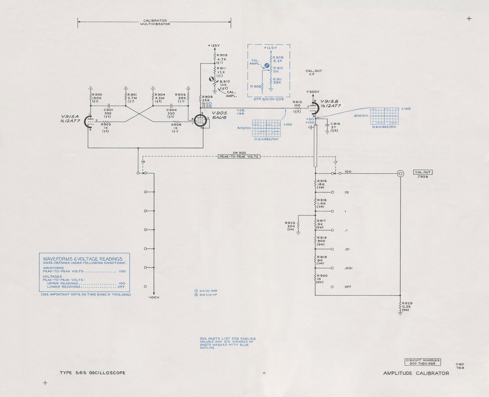
AMPLITUDE CALIBRATOR
The Amplitude Calibrator generates square waves of an
accurate peak-to-peak voltage available in six steps at the
CAL. OUT connector. The square wave output is positive-
going from ground. The frequency is about one kc, rise and
fall times are several microseconds, and the duty factor is
about 0.5. Because of its intended use, only the peak-to-
peak voltage accuracy of the Amplitude Calibrator is given
a specific tolerance.
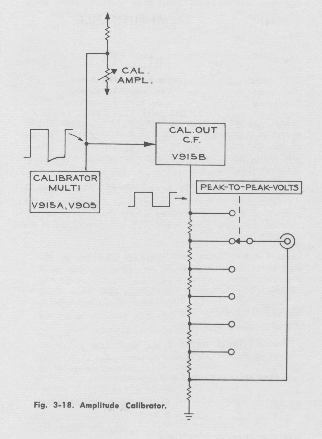
Refer to the block diagram, Fig. 3-18. The Amplitude
Calibrator consists of an astable multivibrator, an output
cathode follower, and a precision output divider. The
multivibrator switches the cathode follower alternately between cutoff and conduction. The cathode follower output voltagis an accurate +100 volts during conduction and zero volts during cutoff. The output divider provides five lower amplitudes from the basic 100 volt square wave. The CAL. OUT voltage is selected by setting the PEAK-TO-PEAK VOLTS switch to the desired value.
Refer to the Amplitude Calibrator schematic diagram in
the back of the manual.
V915A and V905 form a conventional astable plate
coupled multivibrator. In the multivibrator action, V905
operates as a triode with the screen grid acting as the
plate. When V905 conducts, a portion of the cathode
current goes to the pentode plate and drops the plate voltage
to about -20 volts. This voltage is applied to the grid of
V915B. V915B is cutoff and its cathode voltage is zero.
When V905 is cut off, the voltage at its plate is
determined by the voltage divider; R909, R910, and R911. The CAL. AMPL. control, R910, is set during calibration so the voltage at the cathode of V915B will be exactly +100
volts when V905 is cut off.
A 0.25 ohm resistor located between the CAL. OUT coax
connector and ground is approximately equal to the
resistance of the braid of a 42 inch long RG-58A/U coax
cable. Its purpose is to cancel any coax braid ground
current effects on calibrator voltage accuracy that may exist
when the Type 565 AMPLITUDE CALIBRATOR is used as a signal source between the oscilloscope and some other
instrument chassis. The ground currents in this case are
usually developed in the ac power line third-wire grounding
system when the Type 565 and the other instrument
chasses are supplied from different convenience outlets».
§§§
Abbiamo omesso la pur interessante sezione MAINTENANCE del manuale delle istruzioni.
Per consultare le altre schede dedicate a questo oscilloscopio esposto al museo MITI (su proposta di Fabio Panfili) scrivere “565” su Cerca.
Elaborazioni di Fabio Panfili.
Per ingrandire le immagini cliccare su di esse col tasto destro del mouse e scegliere tra le opzioni.