Oscilloscopio Tektronix Type 565. Settima parte.
Nell’inventario D del 1956 si trova al n° 3747 e risulta acquistato nell’agosto del 1964; vi si legge: “Silvestar ltd. Milano. Oscilloscopio Tektronix mod. 565 matr. 689. Dest. Elettronica ₤ 1·678·600”. Insieme alla fotocamera che è al n° 3746, dove si legge: “Silvestar ltd. Milano. Macchina fotografica Tektronix mod. C-12 completa di Bezel-Tektronix. Dest. Elettronica. ₤ 557·700”.
Il testo continua dalla sesta parte.
§§§
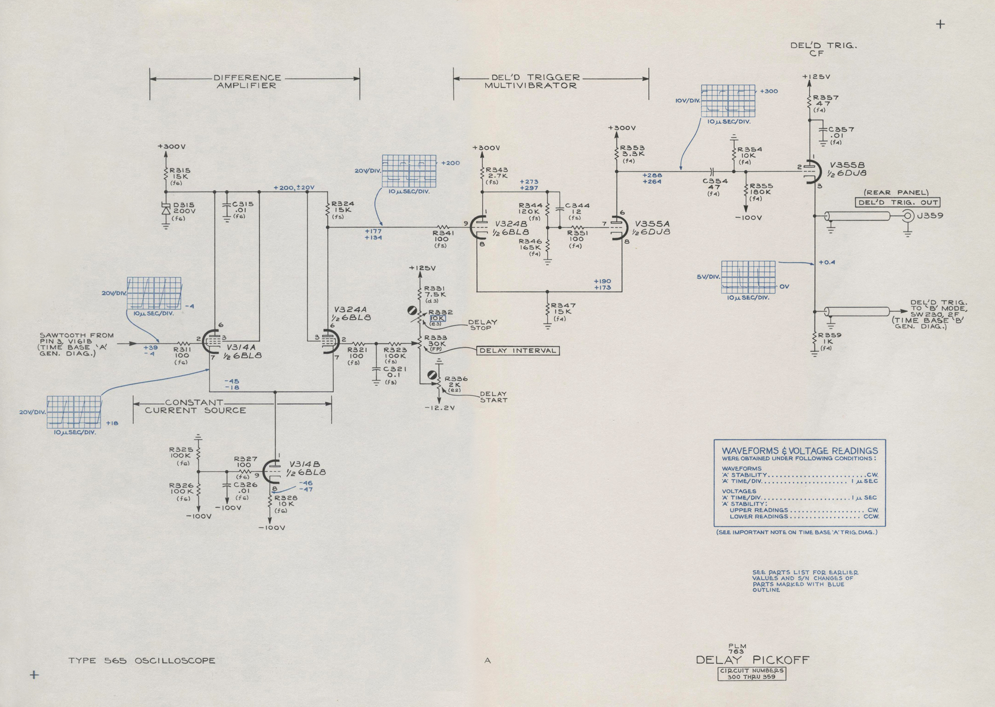
«DELAY PICKOFF
The Delay Pickoff circuit generates a positive-going,
differentiated pulse at a predetermined time during each
sawtooth produced by Time Base ‘A’. The pulse is available at the rear panel for external use and is also coupled to the ‘B’ MODE switch. The relationship between this pulse and Time Base ‘B’ is discussed later in this section under “Time Base ‘B’ Lockout”.
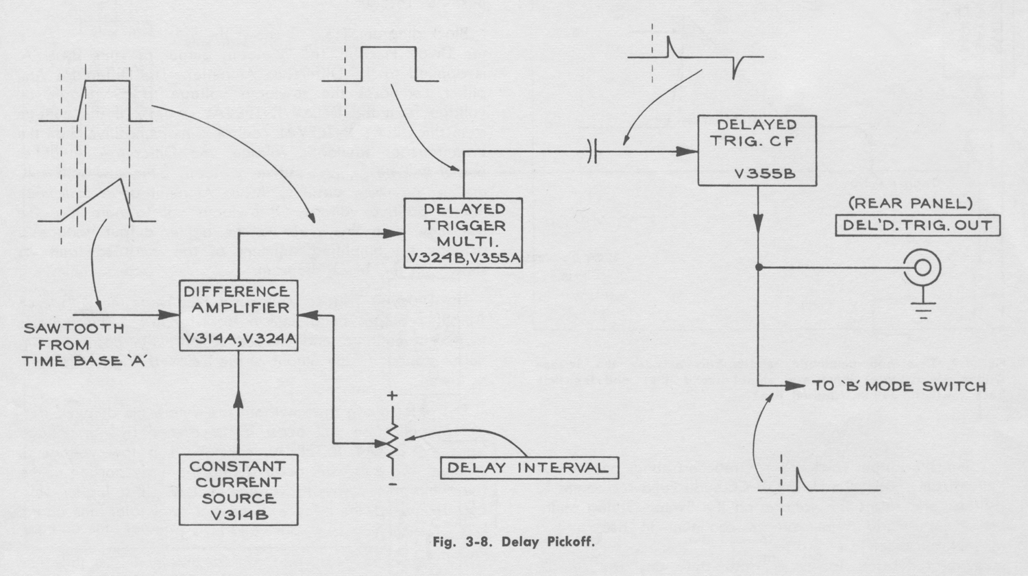
Block diagram, Fig. 3-8, shows the four basic sub-circuits in the Delay Pickoff. The sawtooth output of Time Base ‘A’
is applied to the Difference Amplifier. The Difference Amplifier compares the sawtooth voltage to a variable dc
voltage from the DELAY INTERVAL control. If the voltage
from the DELAY INTERVAL control is more positive than the instantaneous sawtooth voltage, the Difference Amplifier output will be a low positive voltage. If the sawtooth voltage is the more positive, the output will be a somewhat higher positive voltage. It is important to note that the transition from the lower to the higher output voltage is actually an amplified segment of the input sawtooth as shown on the block diagram.
The Delayed Trigger Multivibrator converts the Difference
Amplifier output signal into a fast-rise pulse. This pulse is
then differentiated and clipped so only the positive-going
pulses appear at the output of the Delayed Trigger Cathode
Follower.
The point along the sawtooth rise where the delayed trigger
output pulse will occur is determined by the voltage from the DELAY INTERVAL control. If a low voltage is selected, the pulse will occur during the early portion of the
rise while the sawtooth voltage is low. If a higher voltage is selected, the pulse will occur at some later time during the rise when the sawtooth voltage is proportionally higher.
The maximum delay that can be obtained is slightly less
than the total time duration of the sawtooth rise, which is
determined by the setting of the ‘A’ TIME/DIV. switch. For
example, if the ‘A’ TIME/DIV. switch is set to 1 mSEC, the
maximum DELAY INTERVAL dial setting of 10.00 would result in a 10 millisecond delay between the start of the ‘A’
sawtooth and the delayed trigger pulse output.
The following detailed description refers to the Delay
Pickoff schematic in the back of this manual.
Constant Current Tube
V314B is a constant current source for the Difference Amplifier. The voltage divider formed by R325 and R326
applies about -50 volts to the grid. This stable grid voltage and the high resistance in the cathode circuit force a constant 5 ma to flow through the tube. The Difference
Amplifier will conduct this fixed current, either through one tube or shared between the two tubes.
Difference Amplifier
In the Difference Amplifier, the cathodes of V314A and
V324A are connected together. The tube having the more
positive control grid voltage will determine the voltage on the cathodes of both tubes. For example, assume that the
DELAY INTERVAL control is set to 4.00. The voltage at
the grid of V324A will then be about +36 volts. If Time
Base ‘A’ is in the quiescent state, the voltage at the grid
of V314A will about -3.5 volts. Since the grid of V324A
is more positive, it will establish the common cathode voltage at about +38 volts. Therefore, V314A is deep into cutoff.
V324A conducts and the voltage at its plate is about +121 volts.
As V324A cuts off, its plate voltage rises from about +120
age at the grid of V314A rises. Since V314A is deep in cutoff, the rising voltage does not immediately affect the
Difference Amplifier. But as the sawtooth voltage rises
through the range from about 2.5 volts below to 2.5 volts
above the voltage from the DELAY INTERVAL control, V314A comes out of cutoff and into full conduction. The conduction of V314A forces V324 to reduce conduction. Then, as the sawtooth voltage becomes more positive than the DELAY INTERVAL control voltage, the common cathode voltage rises and cuts off conduction in V324A.
As V324A cuts off, its plate voltage rises from about +120
volts to about +200 volts. The elapsed time from the beginning to the end of this voltage change depends upon the Time Base ‘A’ sweep rate; about 2 seconds at 5 seconds per division and about 0.5 microsecond at 1 microsecond per division. The Delayed Trigger Multivibrator (a Schmitt trigger) converts this variable rate of rise into a voltage step of consistently fast risetime which is independent of the Time Base ‘A’ sweep rate.
Delayed Trigger Multivibrator
When the voltage at the plate of V324A is at the lower
level (about +120 volts), V324B in the Delayed Trigger
Multivibrator is cut off and V355A is conducting. As the
voltage at the plate of V324A rises to about +170 volts
and V324B begins to conduct, the voltage at the plate of V324B drops slightly, lowering the voltage at the grid of
V355A. This reduces the current through V355A. However,
the voltage at the grid of V324B will not permit the
common cathode voltage to drop. Hence, the current given up by V355A is immediately assumed by V324B. This reduces the voltage at the plate of V324B still more, compounding the initial action. Thus, the beginning of conduction in V324B causes the Delayed Trigger Multivibrator to rapidly change states; V324B conducts and V355A cuts off. This produces a fast-rise positive-going voltage step at the plate of V355A.
Delayed Trigger C.F.
The voltage step produced by the Delayed Trigger
Multivibrator is differentiated by the network consisting of C354, R354, and R355, and is applied to the grid of V355B.
Delayed Trigger Cathode Follower V3558 is held near cutoff by R354 and R355. When the delayed trigger pulse appears at the grid, the tube conducts heavily and the pulse isreproduced across R359.
The entire Delay Pickoff circuit resets during the retrace time of the Time Base ‘A’ sawtooth when the voltage at the
plate of V324 drops below about +155 volts. When the
differentiated pulse at the grid of V355B subsided, the tube was again near cutoff. Hence, when the negative going
reset pulse at the grid of V355B drives the tube deeper into
cutoff, very little negative going output signal is produced.
Several important conditions exist at the instant the
delayed trigger output pulse occurs:
1. The voltage from the DELAY INTERVAL control essentially equals the instantaneous sawtooth voltage.
2. Time Base ‘A’ trace will have moved as many graticule
divisions as the DELAY INTERVAL dial setting (10X MAG. off).
3. The time delay between the start of the ‘A’ sawtooth and
the delayed trigger output pulse will equal the DELAY
INTERVAL dial indication times the ‘A’ TIME/DIV. switch
setting.
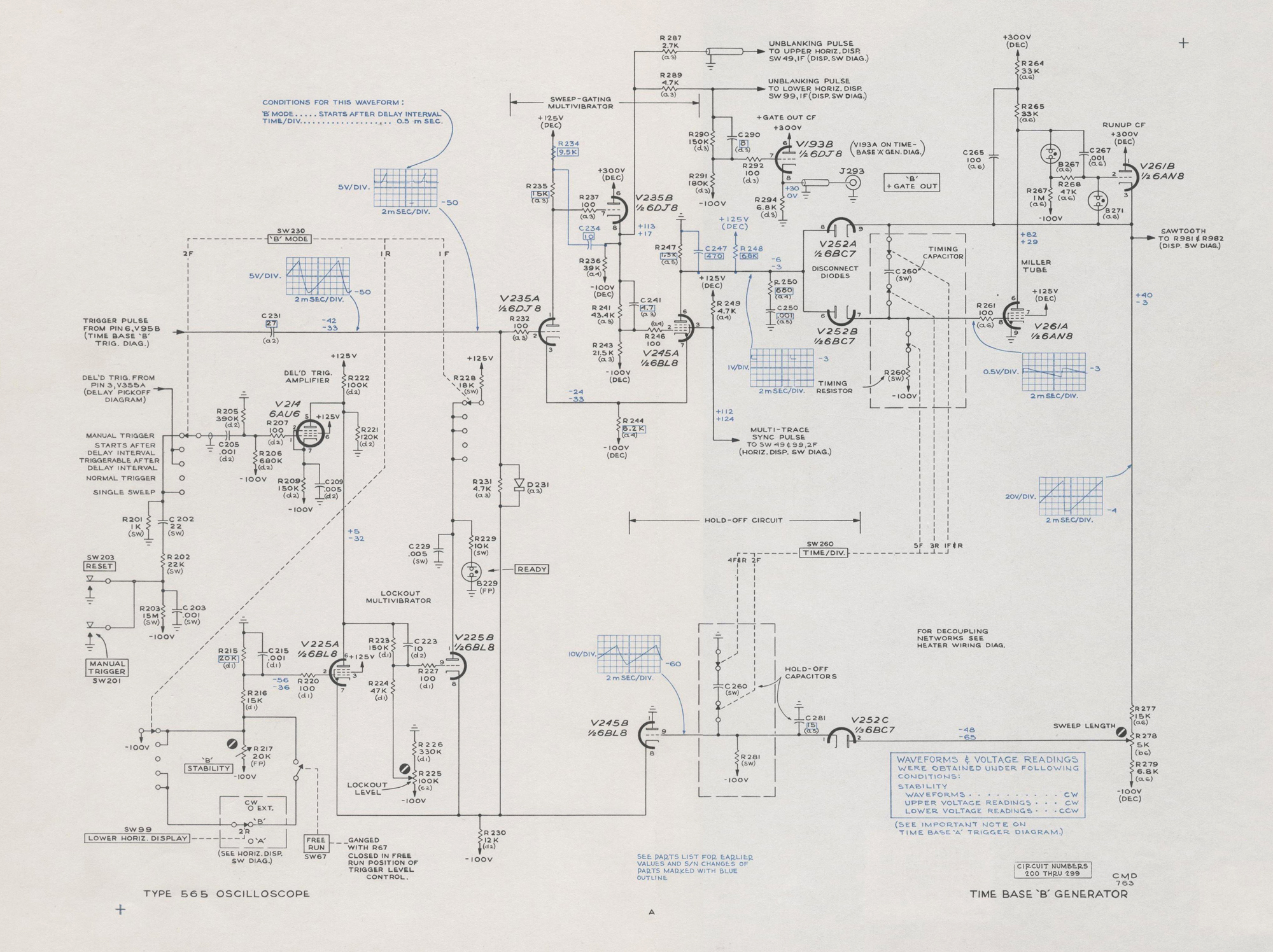
TIME BASE ‘B’ LOCKOUT
As previously mentioned in the description of Time Base
‘A’, the STABILITY control and FREE RUN switch settings determine whether the time base will be inoperative, triggerable, or will free run. Time Base ‘B’ operates in exactly the same manner when the ‘B’ MODE switch is set to NORMAL TRIGGER. However, when the ‘B’ MODE switch is in any other position, there is one additional factor controling Time Base ‘B’; the Lockout Multivibrator.
The Lockout Multivibrator is a bistable electronic switch.
In one state, it permits the STABILITY control or associated switches to have full control of the time base, just as they do in Time Base ‘A’. In the other state, the Lockout Multivibrator over-rides the function of these controls and renders the time base inoperative.
At the beginning of a Time Base ‘B’ sequence, the Lockout
Multivibrator holds the time base in the “Time Base
inoperative” state. A pulse from the Unlock-Trigger
Amplifier will switch the multivibrator to the “Time Base
Operative” state and Time Base ‘B’ then either free runs or
becomes triggerable. When Time Base ‘B’ completes one
sawtooth, the Lockout Multivibrator resets to the “Time Base Inoperative” state. This sequence repeats for each sawtooth produced by Time Base ‘B’.
The following information is closely related to the
STABILITY control discussion under “Time Base Generators” in an earlier portion of this section. For better understanding of Time Base ‘B’ Lockout, the STABILITY control discussion should be read first.
Unless otherwise stated in the following descriptions, the
‘B’ STABILITY control is set for triggered operation and
the ‘B’ MODE switch places the Lockout Multivibrator into one of the following modes of operation.
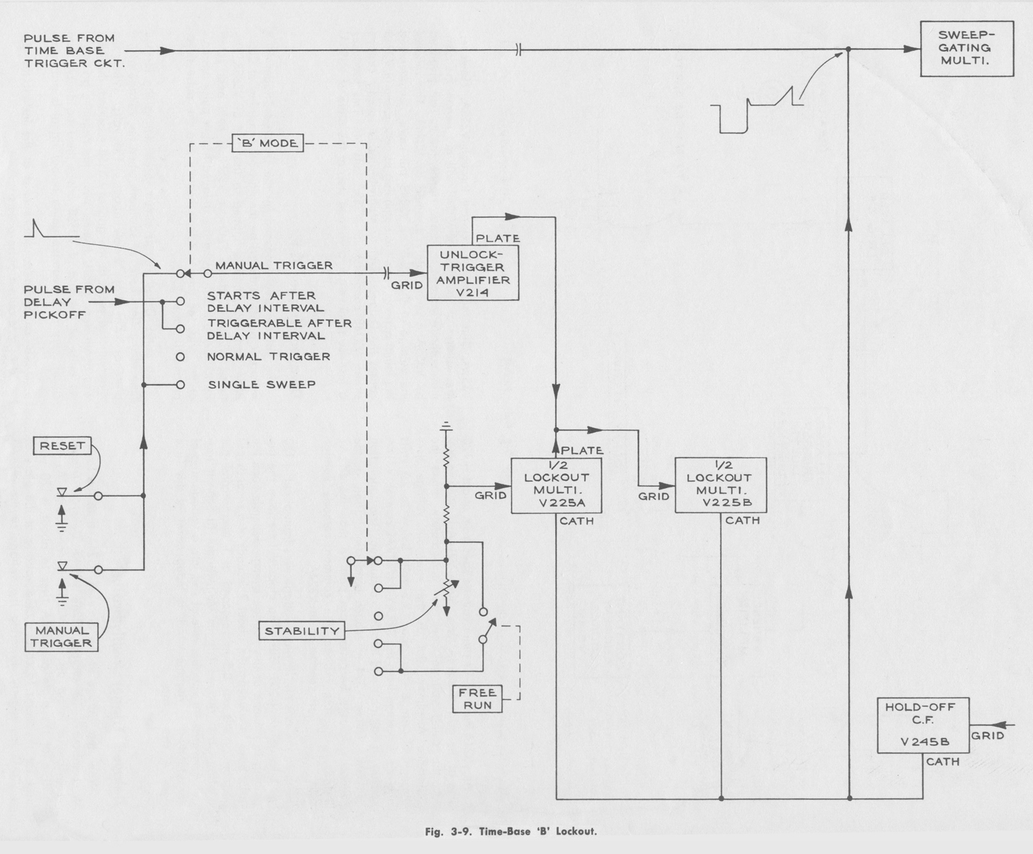
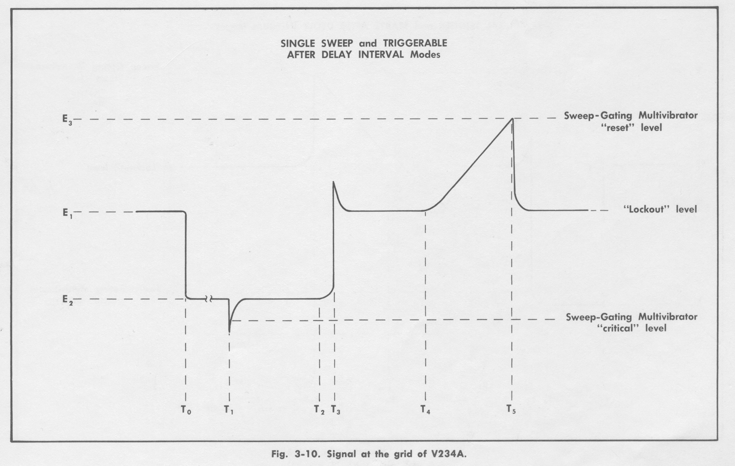
Single Sweep Mode
Refer to the block diagrams, Fig. 3-9 and Fig. 3-10 during
the following descriptions. Fig. 3-10 represents the signal
at the grid of V235A during one cycle of operation as follows:
1. Before to, V225B conducts during the “Lockout” period and holds the grid of V235A at voltage level E1. At this voltage level, the Sweep-Gating Multivibrator cannot be triggered, nor will it free run.
2. When the Single Sweep RESET button is pushed (t0), V225B cuts off. The grid voltage of V235A drops sharply to the level where V225A conducts.
3. The STABILITY control determines the voltage (E2) that
V225A applies to the grid of V235A. The time base is now
in the normal quiescent state and only requires a pulse from
the Time Base Trigger circuit to start the sawtooth. This
could occur immediately or at some indefinite later time.
4. When a trigger pulse is received (t1), the sawtooth cycle
will begin.
5. As the sawtooth reaches about one-half its final
amplitude, the Hold-Off Cathode Follower, V245B, begins to conduct (t2) and V225A cuts off (t3).
6. As V225A cuts off, V225B again comes into conduction
(t3) and raises the grid voltage of V235A to the “Lockout”
level (E1). This voltage level is well below the “reset” level
of the Sweep-Gating Multivibrator and therefore has no
effect on the output sawtooth now in progress.
7. When the output sawtooth reaches about three-fourths its
final amplitude, V245B begins to conduct again (t4) and
V225B cuts off. The sawtooth feedback raises the grid voltage of V235A to the reset level (E3) and stops the sawtooth (t5) in the normal manner.
8. As V2458 continues to conduct, it reproduces part of the
sawtooth retrace at the grid of V235A. But as the voltage
approaches the “Lockout” level (E1) V225B again conducts
and V245B cuts off.
9. The voltage at the grid of V235A is now stable at the
“Lockout” level (E.). The cycle is complete and cannot
repeat until the Single Sweep RESET button is pushed again.
Triggerable After Delay Interval Mode
This mode differs from the Single Sweep mode in that
the “unlocking” pulse comes from the Delay Pickoff Circuit
instead of the RESET push button. Also, the Time Base
‘B’ LEVEL control FREE RUN function is disconnected.
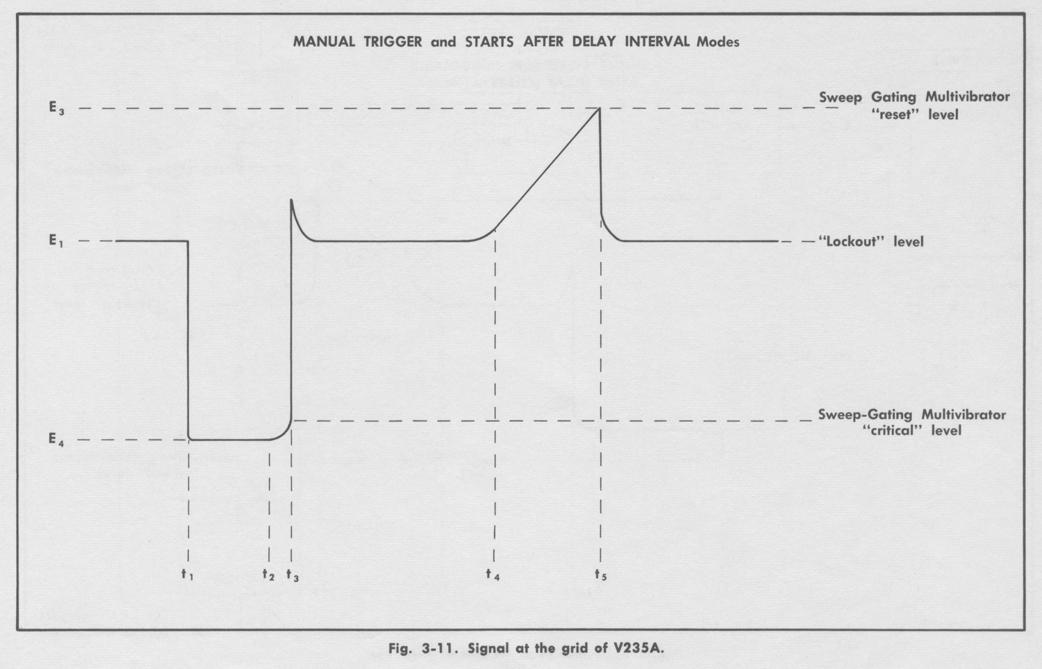
Manual Trigger Mode
The differences between this mode and the Single Sweep
mode are as follows:
1. The “unlocking” pulse comes from the MANUAL TRIGGER push button instead of the RESET push button.
2. When the voltage drops at to (see Fig. 3-11), it drops to
a more negative level (E4) than in the Single Sweep mode.
This level is below the “trip” level of the Sweep-Gating
Multivibrator. Hence, the sawtooth cycle begins
immediately without waiting for a pulse from the Time Base Trigger circuit. This occurs because the ‘B’ MODE switch by-passes the STABILITY control and causes V225A to conduct at the lower level.
Starts After Delay Interval Mode
The only difference between this mode and the Manual
Trigger mode is that the “unlocking” pulse comes from the
Delay Pickoff Circuit instead of the MANUAL TRIGGER push button.
Refer to the Time Base ‘B’ schematic in the back of this
manual during the following description. For the remainder
of this description, the ‘B’ MODE switch can be assumed to
be set at any position except NORMAL TRIGGER.
Since there are two negative feedback paths between
V225A and V225B (pin 6 to pin 9 and pin 8 to pin 7), the
two tubes cannot conduct at the same time. When the time
base is “locked out”, V225B conducts and holds the cathodes of V225A and V245B considerably more positive than their grids. Hence, these two tubes are cut off.
The Unlock-Trigger Amplifier, V214, is self- biased near
cutoff. The positive-going “unlocking” pulse applied to the
control drives V214 into heavy conduction and produces
a high amplitude negative-going pulse at the plate. This
pulse is applied to the grid of V225B through C223-R223,
driving its cathode considerably more negative than the grid
of V225A, causing V225A to suddenly conduct. The voltage at the plate of V225A is already low in the presence of the negative-going pulse from the Unlock—Trigger Amplifier.
Therefore, V225A conducts as a triode with its screen grid
acting as the triode plate. As the pulse at the plate subsides
and the plate voltage tends to rise, a greater portion of the
cathode current in V225A flows to the pentode plate. Thus,
the voltages at the pentode plate of V225A and at the grid
of V225B do not rise after the pulse has subsided. V225A
remains in conduction and V2258 is cut off.
With V225B now conducting, the common cathode voltage
is determined by the switches and STABILITY control in the tube’s control grid circuit. This is exactly the same condition that exists when the time base is operated in the NORMAL TRIGGER mode. The time base will either free run or awaita trigger pulse, depending upon the switch settings in the grid circuit of V225A.
From this point, the cycle continues to the end of the
sawtooth rise as previously described.
At the end of the sawtooth rise, V245B has raised the
common cathode voltage so that both V225A and B are
cut off. When both tubes are cut off, V225B has the more
positive control grid voltage. Hence, as the common cathode voltage goes more negative during the retrace portion of the sawtooth, V225B will come into conduction while V225A is still deep in cutoff. With the cycle completed and V225B conducting, the time base is again “locked out”. The LOCKOUT LEVEL control is adjusted during calibration to set the conduction level of V225B. Whenever V225B conducts, the common cathode voltage should be about half way between the reset and trip voltages of the Sweep-Gating Multivibrator.
The READY lamp lights only when V225B is cut off. The
lamp therefore shows the operator whether or not the Sweep
Gating Multivibrator is ready to operate.
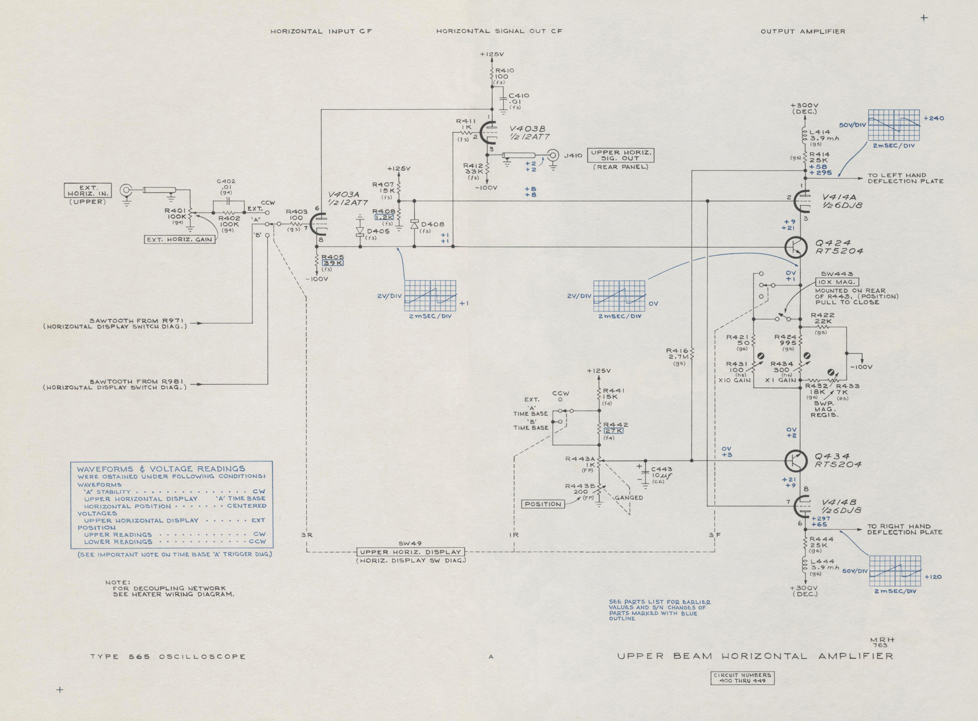
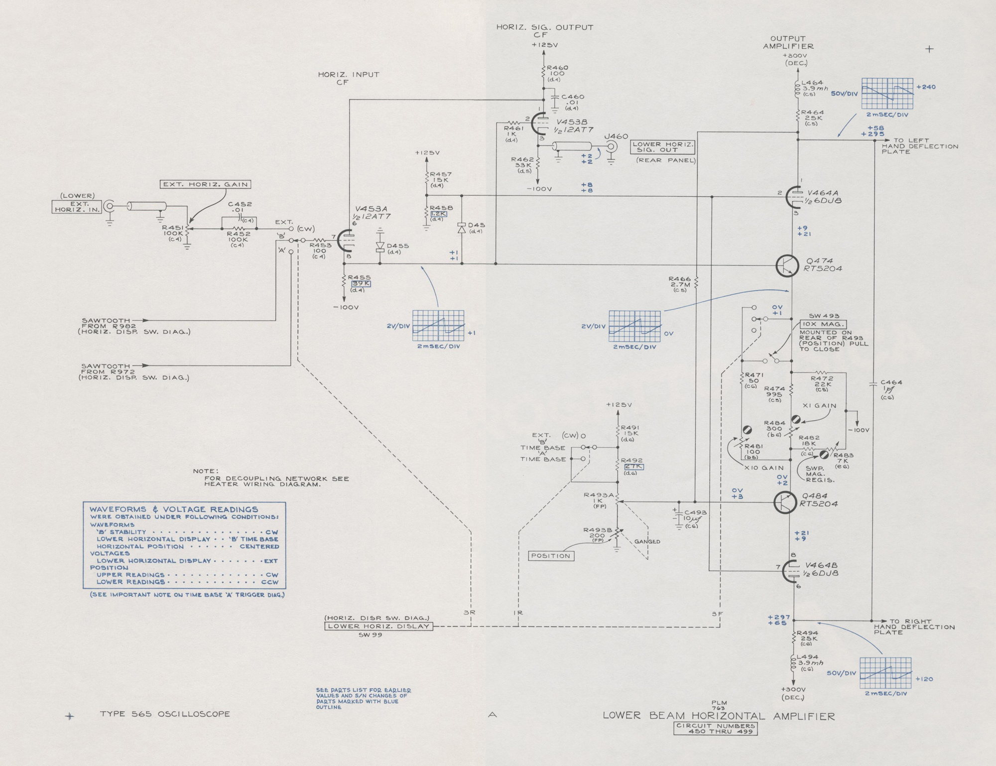
HORIZONTAL AMPLIFIER
The Upper and Lower Beam Horizontal Amplifiers are
nearly identical. The following descriptions apply to both
amplifiers, but the Upper Beam Horizontal Amplifier circuit
reference numbers are used.
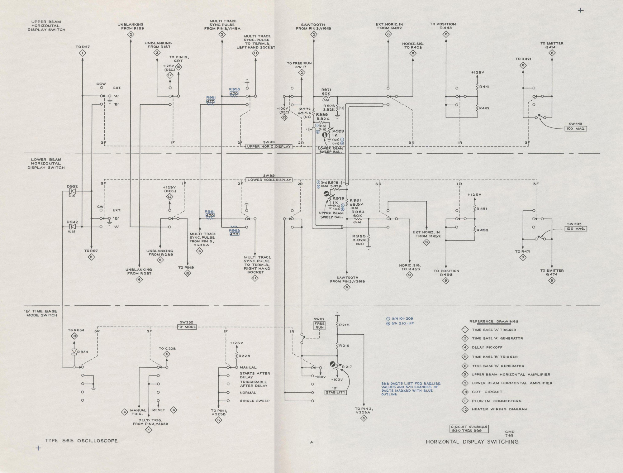
The Horizontal Amplifier input signals can come from Time
Base ‘A’, Time Base ‘B’, or from an external source. The
appropriate signal is selected by setting the Horizontal Display switch.
Each Horizontal Amplifier has two outputs; a push-pull
output connected to one pair of CRT horizontal deflection
plates and a single-ended output at the rear panel for external use. The operator can increase the gain of the push-pull portion of the amplifier ten times by turning on the ten times magnifier (10X MAG.).
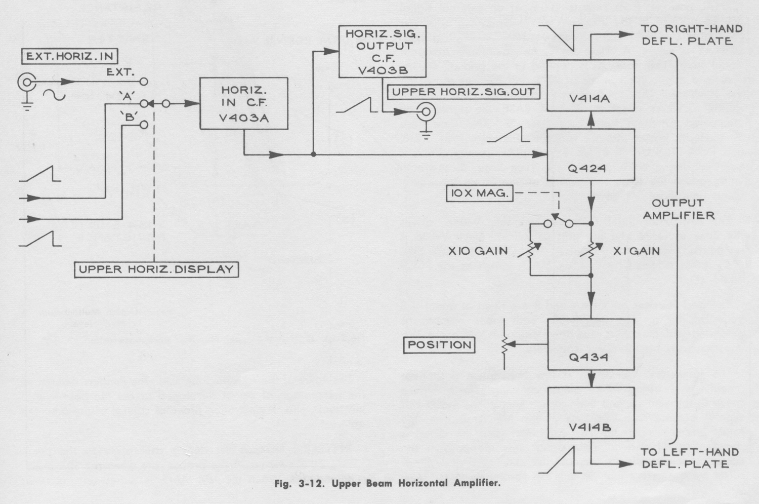
The block diagram, Fig. 3-12, shows the basic sub-circuits
in the Horizontal Amplifier. V403A isolates the amplifier
from the signal source and provides a law driving impedance for Q424. V403B isolates the amplifier from any reasonable load impedance connected to the rear panel horizontal signal output connector.
Q424, V414A, Q434, and V414B form a paraphase
amplifier. The signal applied to Q424 varies the current
through both Q424 and Q434. The current variations pass
through V414A and B and produce a high amplitude voltage swing at the amplifier output. When the 10X MAG. switch is closed (pulled out) the resistance between the emitters of the transistors is decreased and the gain is increased ten times. The POSITION control determines the dc average voltage difference between the right and left hand deflection plates.
Refer to the Upper Beam Horizontal Amplifier schematic
in the back of the manual during the following description.
When the UPPER HORIZ. DISPLAY switch is in the
EXTERNAL position, from zero to 100% of an external signal will be applied to the grid of V403A, depending upon the EXT. HORIZ. GAIN control setting. When UPPER HORIZ. DISPLAY is set to ‘A’ TIME BASE, an attenuated sawtooth signal from Time Bose ‘A’ is applied to the grid of V403A.
The fixed attenuator consists of R971 and R975 as shown on the Horizontal Display Switching schematic. When UPPER HORIZ. DISPLAY is set to ‘B’ TIME BASE, the signal is an attenuated sawtooth from Time Base ‘B’. The Time Base ‘B’ sawtooth passes through variable attenuator R981, R978, and R979. The UPPER BEAM SWEEP BAL. control, R979, is adjusted during calibration so the Time Base ‘B’ sawtooth will produce the same sweep rate on the crt as the equivalent Time Base ‘A’ sawtooth.
The Horizontal Input Cathode Follower, V403A, drives
the base of Q424 and the grid of V403B. Since V403B is
ahead of the Output Amplifier, the UPPER HORIZ. SIG.
OUT is not affected by the 10X MAG. switch or the
POSITION control.
The grid voltages on V414A and B are fixed at about +8
volts by the divider, R407-R408. Both tubes operate as
grounded-grid amplifiers and their cathodes present a low
impedance to the transistor collectors.
The transistors operate as a low impedance paraphase
amplifier with degenerative emitter coupling. The resistance
between the emitters and their current source, the -100 volt
supply, is quite high. Because of this high resistance, the
total current through the two transistors (and the tubes) is
nearly constant and an input signal only reapportions the
current. For example, an increase in current through Q424 is offset by a nearly equal decrease in current through Q434.
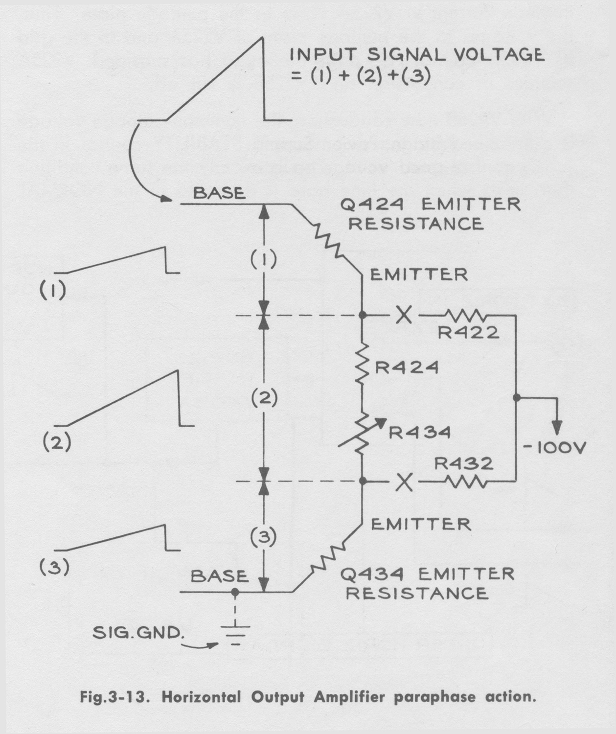
Fig. 3-13 shows how the input signal increases current
through one transistor while equally decreasing current
through the other. The input signal is distributed across the series resistances beginning at the internal emitter resistance of Q424 and ending with the internal emitter resistance of Q434. Since the external circuit is balanced for the two transistors, their internal emitter resistances are equal. Hence, the signal voltages developed across the base- emitter junctions will be equal.
Fig. 3-13 shows that the base of Q424 goes positive with
respect to its emitter while the emitter of Q434 goes
positive with respect to its base. Thus, the two transistors see equal, but opposite phase, input signals. The current
increases through Q424 and decreases through Q434. These
current variations pass through the tubes and develop the
output signal across the plate load resistors.
The value of the resistance between the emitters determines
the percentage of signal developed across the base-emitter
junctions. This degeneration provides control of the amplifier gain.
X1 GAIN, R434, is set during calibration so the beam
moves across the crt at the proper rate when the 10X MAG.
is turned off. When the 10X MAG. is turned on, the series
combination of R421 and R431 is in parallel with R424 and
the X1 GAIN control. The emitter coupling resistance is
decreased and the amplifier gain is increased. X10 GAIN is
set during calibration so the amplifier gain is exactly ten
times greater with the 10X MAG. turned on than with it off.
The current source resistors, R422 and R432, are shown
disconnected in Fig. 3-13 to illustrate that the signal changes the total current through them very little. However, due to the signal across the emitter coupling resistance, the current through R432 decreases slightly while it increases slightly through R422.
When the transistor base voltages are equal, the transistor
currents should also be equal so the beam will be at the
horizontal center of the crt. When the 10X MAG. is turned
on, the emitter coupling resistance is small and the current
will essentially balance. But, when the 10X MAG. is turned
off, the greater resistance can cause a current imbalance, if
the two halves of the amplifier are not exactly equal. Hence,
the SWP. MAG. REGIS., R433, is adjusted during calibration to balance the current with the 10X MAG. turned off. Then, when the beam is at the center of the crt with the 10X MAG. an, it will remain at the center when the 10X MAG. is turned off ».
§§§
Il testo prosegue nella ottava parte.
Per consultare le altre schede dedicate a questo oscilloscopio esposto al museo MITI (su proposta di Fabio Panfili) scrivere “565” su Cerca.
Elaborazioni e testo a cura di Fabio Panfili.
Per ingrandire le immagini cliccare su di esse col tasto destro del mouse e scegliere tra le opzioni.