 Oscilloscopio Tektronix Type 565. Quinta parte.
Nell’inventario D del 1956 si trova al n° 3747 e risulta acquistato nell’agosto del 1964; vi si legge: “Silvestar ltd. Milano. Oscilloscopio Tektronix mod. 565 matr. 689. Dest. Elettronica ₤ 1·678·600”. Insieme alla fotocamera che è al n° 3746, dove si legge: “Silvestar ltd. Milano. Macchina fotografica Tektronix mod. C-12 completa di Bezel-Tektronix. Dest. Elettronica. ₤ 557·700”.
Il testo continua dalla quarta parte.
§§§
«DEMONSTRATION 1: Measuring time between two pulses, the first of which triggers Time Base ‘A’.
Set the controls and switches on the instrument as listed above except as follows;
‘A’ TIME/DIV. .1 mSEC
‘B’ TIME/DIV. 1 μSEC
Apply the Amplitude Calibrator signal to the input of both vertical plug-in units. The Upper Beam should display about one cycle of the squarewave signal.
Set the DELAY INTERVAL dial so the falling portion of
the squarewave is intensified. Advance the Lower Beam
INTENSITY control to obtain a display of normal intensity.
The Lower Beam should now display a horizontally
expanded version of the signal in the intensified segment of the Upper Beam display.
Set DELAY INTERVAL so the Lower Beam trace starts at
About the 50% amplitude level of the squarewave. Multiply the DELAY INTERVAL dial reading (e.g. 5.13) by the ‘A’ sweep rate. The product is the time duration of the
squarewave positive-going half-cycle.
Accuracy
Accuracy is determined by the combination of all the
following factors;
1. The basic accuracy of the Time Base Generator, and
therefore, of time measurements, is ±3%. In measurements
made directly from the crt, this means ±3% of full scale; that is, of the total time represented within the 10 major graticule divisions. However, when the measurement is made by using the sweep delay feature, the accuracy is ±3°/, of reading; that is, of the time being measured.
NOTE
During calibration, the internal DELAY START and DELAY STOP adjustments are set when the Time Base ‘A’ sweep rate is 1 mSEC per division. Therefore, delay measurements made when using the1 mSEC per division ‘A’ sweep rate will generally be most accurate. The delay accuracy obtained at any other ‘A’ sweep rate, 10 μseconds per division or slower, can be increased by calibrating
DELAY START and DELAY STOP at that sweep rate. (In so doing, you may wish to verify that all other ‘A’ sweep rates produce delays that are accurate within 3%). These adjustments do not affect the Time Base ‘A’ crt sweep rate. See the Calibration Procedure, Section 5, step 10.
2. The effect that the linearity of the Delay Interval system has on the measurement accuracy depends on the DELAY INTERVAL dial setting that is used. The linearity factor, as a percentage of reading, decreases as the dial setting increases. With any dial setting, the inaccuracy due to non-linearity will not exceed 0.5% of full scale delay.
3. Measurements are valid only when DELAY INTERVAL dial settings above 0.50 are used.
4. The triggering point can affect the measurement
accuracy since the triggering signal does not rise in zero
time. For example, if the sweep is triggered by the first
portion of the pulse rise, most of the pulse risetime will be
included in the measurement. This is of little concern in
measurements, such as the one made in Demonstration 1,
where the risetime of the signal is a relatively insignificant
percentage of the time being measured. However, as the
risetime percentage of the measured time increases, it
becomes more important that the triggering point be known.
One way to establish a known triggering point is to set the
LEVEL control at one end of the range in which a stable,
triggered Upper Beam display is obtained. Most of the
risetime of the signal will be included in the measurement
when:
a. ‘A’ TRIGGER SLOPE is set to + and LEVEL is set to
the — end of the “triggering” range (positive-going
signals), or
b. ‘A’ TRIGGER SLOPE is set to – and LEVEL is set to
the + end of the “triggering” range (negative-going signals).
5. The Time Base ‘A’ Trigger, Time Base ‘A’ Generator,
Delay Pickoff, and Time Base ‘B’ Generator circuits typically require a total of about 1.0 to 1.5 microseconds to respond to the signal event which triggers Time Base ‘A’. This small delay need not be considered unless it is a significant percentage of the time being measured. When necessary, add the circuit delay time to the measured time.
6. The 5, 2, and 1 μSEC/DIV A sweep rates generally are
not used for measurements such as those described in
Demonstration 1.
Summary—The method described in Demonstration 1 will
provide greatest time measurement accuracy when:
a. the internal DELAY START and DELAY STOP adjustments are calibrated at the sweep rate to be used,
b. dial settings above 4.0 or 5.0 are used,
c. the event triggering Time Base ‘A’ has a fast rise time,
and
d. Time Base ‘A’ sweep rates of 50 μSEC/DIV. or slower
are used.
DEMONSTRATION 2: Measuring time between two pulses of a pulse train, neither of which triggers Time Base ‘A’.
Set the controls and switches on the instrument as listed
except as follows:
‘A’ TIME/DIV. .2 mSEC
Apply the Amplitude Calibrator signal to the input of both vertical plug-in units. The Upper Beam should display about two cycles of the squarewave signal. Set the
DELAY INTERVAL dial so the squarewave rise located near the center of the Upper Beam display is intensified.
Advance the Lower Beam INTENSITY control to obtain
a display of normal intensity. The Lower Beam should now
display a horizontally expanded version of the intensified
Upper Beam display segment.
Set DELAY INTERVAL so the 50% amplitude level of the
squarewave rise intersects the vertical line at the center of the graticule. Note the exact DELAY INTERVAL dial setting (e.g. 5.14). Turn the DELAY INTERVAL dial clockwise until the 50% amplitude level of the squarewave fall intersects the same vertical graticule line used with the previous dial setting. Again note the exact DELAY INTERVAL dial setting.
Subtract the first dial setting from the second. The product of this difference and the Time Base ‘A’ TIME/DIV. equals the time duration of the squarewave positive-going half-cycle (between the 50% amplitude points).
Accuracy
Accuracy is determined by the combination of all the
following factors:
1. The basic accuracy of the Time Base ‘A’ generator is the same as described in Demonstration 1.
2. The percentage of error that the Delay Interval system linearity adds to the measurement depends on the numerical
difference between the two dial settings used; this error
decreases as the numerical difference increases. The amount of time error in the measurement is less than 1% of the full
scale delay (1%, of ten times the ‘A’ sweep TIME/DIV.).
However, this applies only when the DELAY INTERVAL dial settings are separated by at least 100 minor dial divisions.
NOTE
When the separation between dial settings is one hundred minor dial divisions or less, the desired time measurement can often be made more accurately by direct reading from a magnified crt display. See Demonstration 3; Magnification.
3. Measurements are valid only when DELAY INTERVAL
dial settings above 0.50 are used.
4. The accuracy of time measurements made according to Demonstration 2 is independent of the inherent circuit delays and of the triggering point (discussed in Demonstration 1), provided the ‘A’ LEVEL control setting is the same for each of the two dial readings.
5. The 2 and 1 μSEC/DIV. A sweep rates generally are not used in measurements such as those described in Demonstration 2.
Summary— The method described in Demonstration 2 can
provide a time measurement accuracy within 1% of reading.
Accuracy will be greatest when:
a. the internal DELAY START and DELAY STOP
adjustments are calibrated at the sweep rate to be used, and
b.the numerical difference between the two DELAY INTERVAL dial settings is greatest.
DEMONSTRATION 3: Magnification
Complex signals often consist of a number of individual
events of different amplitudes. Since the trigger circuits
of the Type 565 are sensitive to signal amplitude, a stable
display will normally be obtained only when the sweep is triggered by the event having the greatest amplitude.
The “Starts After Delay Interval” mode permits the start of a sweep to be delayed for a selected time after the signal event having the greatest amplitude. Any event within the series of events may then be displayed in magnified form as follows:
Set the controls and switches on the Type 565 as listed. Apply the Amplitude Calibrator signal to the input of both
vertical plug-in units. The Upper Beam should display
several cycles of the squarewave signal. Set the DELAY
INTERVAL dial to intensify one of the positive-going pulses.
Advance the Lower Beam INTENSITY control to obtain
a display of normal intensity. The Lower Beam display
should now contain the same signal information as the
intensified Upper Beam trace segment, but horizontally
expanded (magnified) ten times.
Increase the Time Base ‘B’ sweep rate to 1 microsecond
per division. Set the DELAY INTERVAL dial so the intensified segment in the Upper Beam trace extends throughout the rise of one of the positive-going pulses. The Lower Beam display now gives X1000 magnification.
Slowly turn the DELAY INTERVAL dial. Note that any
portion of the Upper Beam display can be brought into view in magnified form on the Lower Beam display (except for a small portion at the beginning and end of the Upper Beam Display). The DELAY INTERVAL dial indication corresponds to the number of major graticule divisions
between the beginning of the Upper Beam trace and the
beginning of the intensified trace segment; e.g. 7.00 = 7
major divisions.
Set the Time Base ‘B’ sweep rate to 10 microseconds per division. Set the DELAY INTERVAL dial so a squarewave
rise is centered in the Lower Beam display. Set UPPER
HORIZ. DISPLAY to ‘B’ TIME BASE and turn on the Upper Beam IOX MAG. Set the Upper Beam horizontal POSITION so the squarewave rise is visible in the Upper Beam display.
The Lower Beam now gives 100 times magnification
and the Upper Beam gives 1000 times magnification of the
information that was contained in the intensified segment of the original Upper Beam display.
Both the Upper and Lower Beam display will probably
exhibit some horizontal jitter. Part of the jitter is due to a
slight inconsistency in the Amplitude Calibrated signal
frequency, and part is due to jitter in the delay system. The jitter contributed by the delay system is less than 0.05%
of the Time Base ‘A‘ sweep rate (0.05% of 1 millisecond
= 0.5 microsecond). With 1000 times magnification, the
Upper Beam sweep rate is 1 microsecond per division.
Hence, the jitter due to the delay system is less than one-half major division.
Accuracy
1. The accuracy of time measurements made from
magnified displays such as those described in the foregoing
paragraphs, depend solely on the Time Base ‘B‘ sweep rate
accuracy (±3%, with the 10X MAG. off and ±5 with the10X MAG. on).
DEMONSTRATION 4: Delayed Trigger
Ordinarily, a signal which is to be displayed is also used to trigger the oscilloscope sweeps so a stable display is obtained. In some situations, it may be desirable to reverse this situation. The sweep-related output pulses, available at the rear panel of the Type 565, can be used* as the input or triggering signals for external devices. The output signal of the external device will then produce a stable display while the oscilloscope sweep free-runs.
To demonstrate one method of performing this operation,
proceed as follows:
Set the controls and switches on the Type 565 as listed
except as follows;
‘A’ TRIGGER source EXT.
‘A’ TRIGGER COUPLING DC
‘A’ TIME/DIV. 10 μSEC
‘B’ MODE NORMAL TRIGGER
‘B’ TRIGGER LEVEL FREE RUN
DELAY INTERVAL 1.00
INTENSITY (Upper) normal
Connect: (rear panel and front panel connections)
‘B’ + GATE OUT to ‘A’ TRIG. IN
DEL’D TRIG. OUT to INPUT of the Upper Beam plug-in unit
Set ‘A’ TRIGGER LEVEL mid-way between ‘O’ and FREE
RUN so Time Base ‘A’ triggers on the rise of the ‘B’ + GATE
OUT signal. The Upper Beam should now display a narrow,
positive-going pulse.
*Output current must not exceed 2 ma peak.
The oscilloscope display that you have established shows a pulse that is available from the Type 565 during each Time Base ‘A’ sweep. In a practical application, the pulse would
not be applied to the vertical input of the oscilloscope, but
instead to some external device to be tested. The pulse would serve as the trigger pulse for the external device and the output of the device would be displayed on the oscilloscope.
Since the pulse has a known time-relationship to
each Time Base ‘A’ sweep, the output of the device will
provide a stable display on the oscilloscope, as though the oscilloscope were triggered in the normal manner.
The set-up described in the foregoing paragraphs permits you to vary the repetition rate of the pulse applied to the
external device. To do this, monitor the pulse signal on another oscilloscope and set ‘B’ TIME/DIV. and VARIABLE for the desired repetition rate. ‘A’ TIME/DIV. controls only the display sweep rate as long as the Time Base ‘A’ Sweep rate is at least twice that of Time Base ‘B’.
Set ‘B’ MODE to MANUAL TRIGGER and press the MANUAL TRIGGER push-button. This set-up permits you to produce each DEL’D TRIG. OUT pulse manually.
DEMONSTRATION 5: Pulse Generation The ‘B’ + GATE OUT signal of the Type 565 can be used as a low-current*, variable repetition rate, variable dutyfactor pulse generator in applications where the pulse shape is of secondary importance. To use the Type 565 in this manner, proceed as follows:
Set
UPPER HORIZ. DISPLAY ‘A’ TIME BASE
LOWER HORIZ. DISPLAY ‘B’ TIME BASE
‘B’ MODE STARTS AFTER DELAY INTERVAL
DELAY INTERVAL about 0.50
LEVEL (‘A’ and ‘B’) FREE RUN
The pulse signal is available at the ‘B’ + GATE OUT
connector on the rear panel. Monitor the signal on another
oscilloscope and establish the desired pulse repetition rate by setting the Type 565 ‘A’ TIME/DIV. and VARIABLE. Establish the desired duty factor by setting ‘B’ TIME/DIV.
The maximum pulse repetition frequency that can be
obtained in this manner is about 10 to 12 kc. Maximum duty factor is about 0.6, decreasing with faster sweep rates.
A slight alteration in this set-up will produce a double- pulse generator. To do this, start with a B sweep rate that is
at least 5 times faster than the A sweep rate. Set DELAY
INTERVAL to about 5.00. Connect a 100 pf capacitor between the center conductors of the A+ GATE OUT and DEL’D TRIG OUT connectors on the rear of the instrument.
The B + GATE OUT pulse will now occur twice during each A sweep; the first beginning as A sweep begins and
the second begins at the end of the delay interval.
The time separation between pulses is controlled by setting
DELAY INTERVAL. The minimum separation that can obtained is a function of the Time Base B Generator hold-off time.
*Output current must not exceed 2ma peak.
Triggerable After Delay Interval
Complex signals often contain a number of individual
events of different amplitudes. Since the trigger circuits in the Type 565 are sensitive to signal amplitude, a stable display will normally be obtained only when the sweep is
triggered by the event having the greatest amplitude.
The TRIGGERABLE AFTER DELAY INTERVAL feature of the Type 565 provides a means of triggering the sweep by events other than those having the greatest amplitude. The following instructions permit you to demonstrate that Time Base ‘B’ can be triggered by virtually any event within a series of events.
Set the controls and switches on the instrument as listed
except as follows:
Lower Beam INTENSITY for normal display
Time Base ‘B’ TRIGGER controls. some settings as Time controls Base ‘A’ TRIGGER
Connect the CAL. OUT signal to both the Upper and Lower
Beam vertical input connectors. Each beam should present
a square wave display.
Turn the DELAY INTERVAL dial about 2 turns in either
direction. Notice that both the Lower Beam display and
the brightened segment in the Upper Beam display, move
smoothly across the crt.
Set the DELAY INTERVAL dial so the brightened segment
in the Upper Beam display begins about in the middle of a
pulse top. Notice that the Lower Beam display also begins
in the middle of a pulse top. Now, set the ‘B’ MODE switch
to the TRIGGERABLE AFTER DELAY INTERVAL position.
Notice that the brightened segment in the Upper Beam
display has shifted to the next pulse on the right. The Lower
Beam display now begins within the rising portion of the pulse.
Now turn the DELAY INTERVAL dial several full turns.
The brightened segment in the Upper Beam display should
jump from one pulse to the next. In this demonstration,
the Lower Beam display appears unchanged because all
pulses are identical.
The display is produced in the following manner:
Time Base ‘B’ produces one sweep for each ‘A’ sweep.
‘B’ sweep will begin at some time after the start of ‘A’
sweep. This time is the total of (1) the Time Base ‘A’ sweep
rate (TIME/DIV.) multiplied by the DELAY INTERVAL dial setting, plus (2) the time between the end of this delay
interval and the next event in the signal which can trigger Time Base ‘B’.
It is possible that Time Base ‘B’ might not be triggered
until long after Time Base ‘A’ has completed its sweep. If
separate triggering signals are being applied to the two time
bases, Time Base ‘A’ could produce several additional sweeps
before Time Base ‘B’ receives a triggering signal. Because
of this, the brightened trace segment could appear at any
point on the Upper Beam trace or might not appear at all.
Delayed Trigger Output
The delayed trigger output pulse is always available at the rear panel connector at the predetermined time during each sawtooth produced by Time Base ‘A’, regardless of the ‘B’ MODE switch setting. This output signal is discussed in greater detail under “Starts After Delay lnterval”, Demonstration 4.
External Horizontal Inputs
For special applications, you can deflect either beam horizontally with an externally derived signal. This permits you to use the oscilloscope to plot one function versus
another. The maximum bandpass of the horizontal amplifier
occurs at the fully clockwise setting of the EXT. HORIZ. GAIN control; dc to at least 350 kc.
To use an external signal for horizontal deflection, connect the signal to either the Upper or Lower Beam EXT. HORIZ. IN connector. Place the appropriate horizontal display switch in the EXT. position. The horizontal deflection factors can be varied by adjusting the EXT. HORIZ GAIN
control such that a one volt peak-to-peak signal will produce from zero to at least 10 major graticule divisions of deflection.
The 10X MAG. switch has no effect when external horizontal deflection is used.
Amplitude Calibrator
The amplitude calibrator provides a convenient source of square waves of known amplitude at a frequency of approximately 1kc. The square waves are used primarily to adjust probe compensation and to verify the amplitude calibration of the oscilloscope vertical deflection systems.
Calibrator square waves are adjustable from 1 millivolt to 100 volts, peak-to-peak, in decade steps. The amplitude is controlled by the setting of the PEAK-TO-PEAK VOLTS switch. The output voltage is ac-curate within 3% of the PEAK- TO-PEAK VOLTS switch setting when the output is connected to a high-impedance load such as the INPUT connector of a vertical plug-in unit.
When the .001, .01, .1 volt settings of the PEAK-TO-PEAK
VOLTS switch are used, it will be necessary to use a coax
cable to take the signal from the CAL. OUT connector. The
outer conductor of the cable must make good contact with
the shield portion of the CAL. OUT connector in order to
obtain an accurate output voltage.
AUXILIARY FUNCTIONS
Intensity Modulation
The rear panel jacks marked UPPER BEAM CRT GRID and LOWER BEAM CRT GRID permit external signals to vary the intensity of the traces (Z-axis modulation). This feature can be used to refer oscilloscope time measurements to an external timing standard.
In some applications, you may wish to use the VARIABLE
TIME/DIV. control at an uncalibrated position to obtain a
sweep rate other than those provided by the TIME/DIV.
switch. Intensity modulation with time-marker pulses will
permit you to establish and monitor the desired sweep rate.
This will eliminate the need for a separate vertical display of a time reference signal.
Fast-rise pulses of short duration are usually used for
intensity modulation because they produce an easily
interpreted display. When other types of signals are used, it is important to note that sinewaves below 250 cycles will be
attenuated due to the ac signal coupling within the
instrument. The signal amplitude required for visible trace
modulation depends upon the intensity level of the
unmodulated trace.
Trace Photography
Several features of the Type 565 Oscilloscope are
particularly important when photographying the crt display. The rubber washers normally installed between the graticule and the bezel should be removed when either the light filter or a camera-mount bezel is installed. When a light filter is used, the graticule should be placed between it and the crt.
There are two pairs of holes in the graticule for the scale
illumination pilot lamps. One pair is colored red and will
produce red graticule lines when aligned with the pilot lamps.
The second pair is clear and will produce white graticule
lines. White lines should be used whenever the light filter
is installed or when photographs are being taken. When the
trace is viewed without a light filter, the red lines are usually easier to see. In all cases, the side of the graticule that bears the scribed lines should be placed against the crt face.
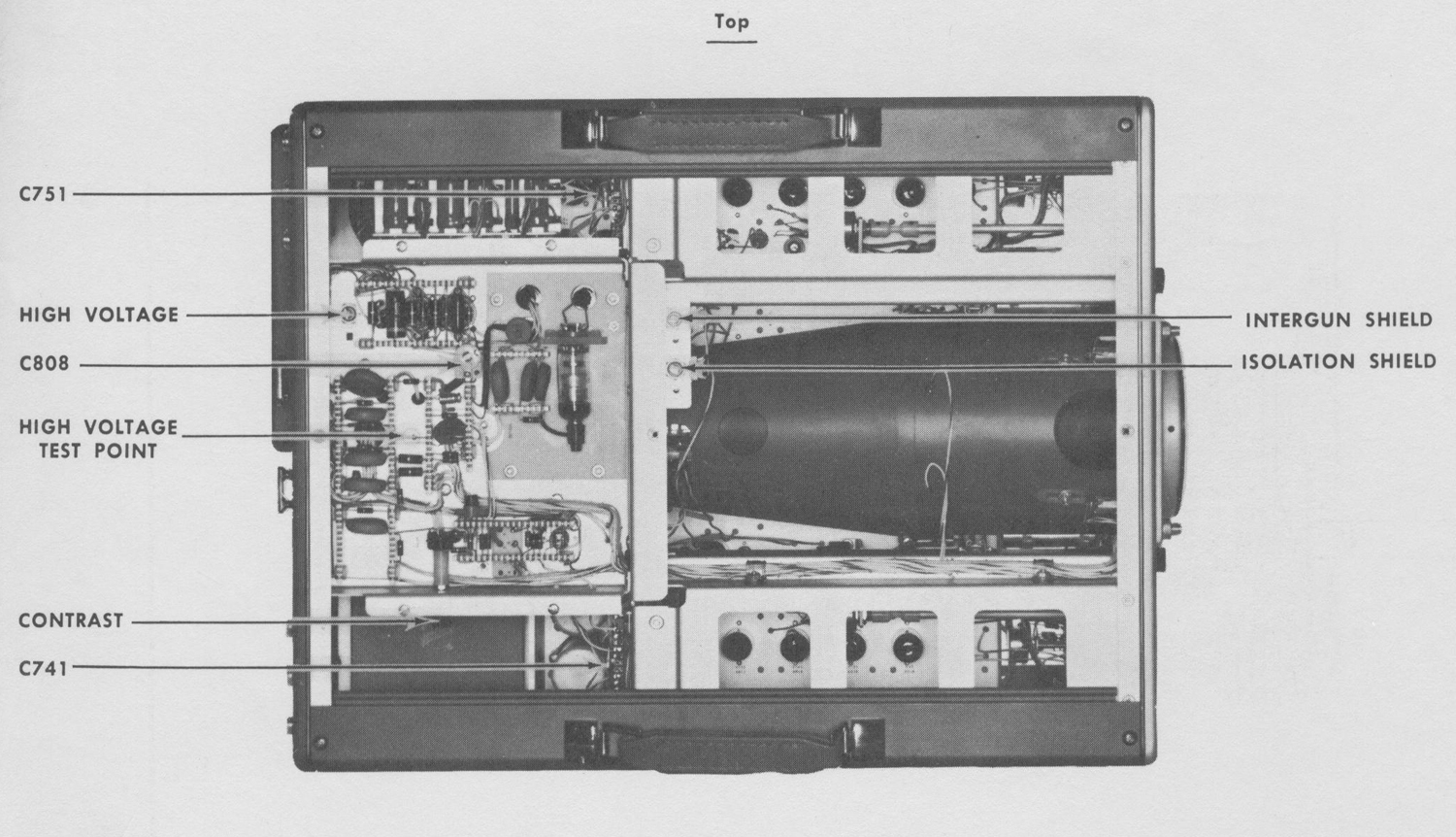
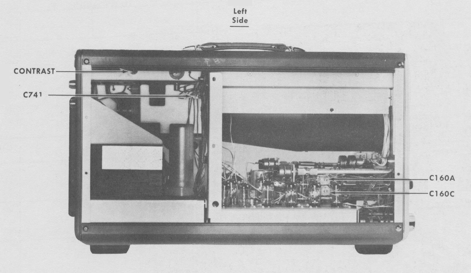
The CONTRAST control, located inside the instrument at
the left side of the High Voltage Power Supply chassis, permits you to control the relative intensity of the intensified trace segment obtained in delayed sweep operation. This control is usually set fully clockwise (greatest contrast) for normal viewing. However, it may require resetting for less contrast while photographs are being taken so all portions of the picture will be properly exposed.
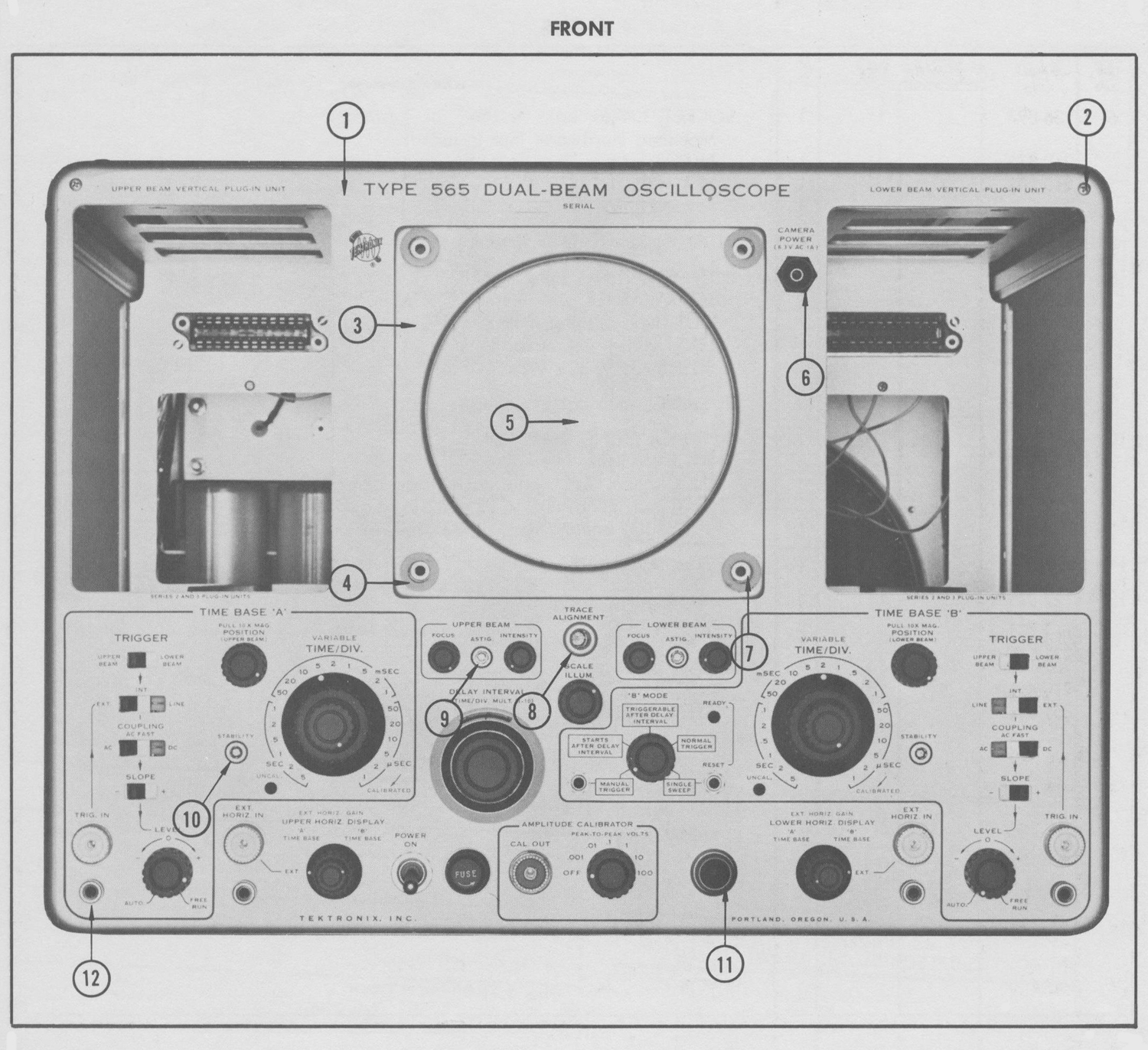
The CAMERA POWER jack, on the front panel, provides a
convenient power source for future camera accessories.
The Single-Sweep feature, described previously in this
section, is often used when non-repetitive waveforms are photographed.
Aux. Power Jack
The auxiliary power jack on the rear panel is provided to
power future accessories for the Type 565, as well as other devices».
§§§
Il testo prosegue nella sesta parte.
Per consultare le altre schede dedicate a questo oscilloscopio esposto al Museo MITI (su proposta di Fabio Panfili) scrivere “565” su Cerca.
Elaborazioni e testo a cura di Fabio Panfili.
Per ingrandire le immagini cliccare su di esse col tasto destro del mouse e scegliere tra le opzioni.