 Oscilloscopio Tektronix Type 565, serial 689. Terza parte.
Nell’inventario D del 1956 si trova al n° 3747 e risulta acquistato nell’agosto del 1964; vi si legge: “Silvestar ltd. Milano. Oscilloscopio Tektronix mod. 565 matr. 689. Dest. Elettronica ₤ 1·678·600”. Insieme alla fotocamera che è al n° 3746, dove si legge: “Silvestar ltd. Milano. Macchina fotografica Tektronix mod. C-12 completa di Bezel-Tektronix. Dest. Elettronica. ₤ 557·700”.
Le prossime schede riportano parte delle istruzioni tratte dal manuale conservato presso la sezione Elettronica del Montani.
§§§
«SECTION I CHARACTERISTICS
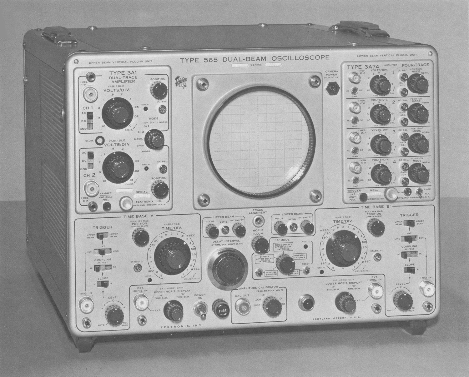
The Type 565 is a dual-beam oscilloscope; essentially two oscilloscopes in one cabinet. Two internal horizontal and two plug-in vertical deflection systems permit independent operation of the two cathode-ray tube (crt) beams. Either
of the two time-base generators can control the sweep of either or both of the beams.
Each vertical deflection system utilizes any of the Tektronix non-sampling signal amplifier plug-in units intended for use with 560-Series instruments. The choice of plug-in units depends on the application and those used need not be the some type.
Special circuits in the Type 565 Oscilloscope permit an accurate, continuously variable delay in the presentation of
a sweep from 10 microseconds to 50 seconds after receipt of a fast rise triggering impulse. This feature permits expanded observation of a small portion of the normal sweep, accurate measurement of signal jitter, precise time measurement and many other uses.
VERTICAL DEFLECTION SYSTEM
The characteristics of both vertical channels are those of the plug-in units used. The capacitances of the two vertical deflection plate systems of the cathode-ray tube are equalized to assure uniform plug-in unit high frequency response.
HORIZONTAL DEFLECTION SYSTEM
Sweep Rates—Time Base ‘A’ and Time Base ‘B’
Calibrated sweep rates of 1 microsecond to 5 seconds per division in 21 steps. An uncalibrated control permits sweep rates to be varied continuously between 1 microsecond and about 12 seconds per division.
Sweep rate accuracy (with 10X MAG. turned off): Upper Beam driven by Time Base ‘A’ and Lower Beam driven by Time Base ‘B’; within 3%.
Both beams driven by Time Base ‘A’; Lower Beam sweep
rate is accurate within 4%.
Both beams driven by Time Base ‘B’; Upper Beam sweep
rate is accurate within 4%,.
Simultaneous crossed operation not recommended (Upper Beam driven by Time Base ‘B’ and Lower Beam driven by Time Base ‘A’).
10X Magnifier—Upper and Lower Beam
Provides a horizontal magnification of X10 of the center 1-centimeter portion of the unmagnified crt display when the internal time base generators provide the horizontal deflection. Extends the fastest sweep rate of either beam to 0.1 microsecond per division. Magnified sweep rates are accurate within 5% except in simultaneous crossed operation.
External Horizontal Inputs—Upper and Lower Beams
Deflection Factor—Continuously variable from zero to at least 10 major graticule-divisions deflection per volt.
Maximum Input Voltage-300 volts, rms.
Frequency Response—Dc to at least 350 kc (-3 db) at maximum sensitivity.
Input Impedance—Resistance, about 100 kilohms.
Parallel capacitance is 30-50 pf, depending on the EXT.
HORIZ. GAIN control setting.
TRIGGERING—TIME BASES ‘A’ and ‘B’
Trigger Signal Sources
Upper or lower Beam vertical signal, external signals, or power line signal.
Triggering Modes
AC, AC Fast, DC, and Automatic.
Triggering Signal Requirements
Internal—Depends upon the plug-in unit. Dc to 1 megacycle sinewave; typically, signals which produce 0.3 major graticule division vertical deflection will provide stable triggering with proper setting of the LEVEL control. Above 1-megacycle, increased signal amplitude is required.
External—Dc to 1-megacycle sinewave; less than 1-volt to
15-volts, peak, depending upon the LEVEL control setting.
Above 1-megacycle, greater signal voltage is required.
(Sweeps will trigger on signals greater than 15 volts peak,
but the LEVEL control operates over a range of about + and -15 volts.)
Delayed Sweep See Section 2, “Starts After Delay Interval”.
CATHODE RAY TUBE (crt)
Type—T565P (x), Aluminized.
Phosphor—(x)—Type P2 normally supplied; P31 is recommended for fast sweep rate, low duty-cycle applications.
P1, P7, and P11 phosphors optional.
Internal Unblanking
Dc coupled to blanking deflection plates.
External Intensity (Z axis) Modulation — Upper
and Lower Beams
Ac coupled to crt control grids through rear panel input jacks. Input time constant depends on INTENSITY control setting and external circuit impedance; typically about 3.5
milliseconds at normal intensity with low external impedance.
Typically, a 10 volt peak-to-peak signal will produce visible
intensity modulation.
Dual Trace Chopped Blanking
Crt circuit permits vertical plug-in units with multi-trace
blanking to turn off the display while switching between
input channels.
Useable Viewing Area
10 by 10 centimeters. 10-centimeter total vertical deflection
consists of 8 centimeters for each beam with 6 centimeters common to both beams.
Graticule Markings
Marked in 10 vertical and 10 horizontal 1-centimeter (major) divisions. 2-millimeter markings (minor divisions) on the vertical centerline and on the horizontal centerlines of both the Upper and Lower Beam; 4 centimeters from top and bottom.
Graticule Illumination
Variable edge lighting.
Alignment
Traces are parallel to one another within ¼ major division per 10 major divisions when both traces are vertically positioned at the center of the crt.
AMPLITUDE CALIBRATOR
Output Signal
Square waves at about 1,000 cycles.
Output Voltage
1 millivolt to 100 volts in decade steps.
Accuracy
Peak-to-peak amplitude within 3% of indicated voltage as measured between center jack and the shield portion of the CAL. OUT connector. Accuracy is degraded somewhat it CAL. OUT is connected to loads under 1-megaohm.
OTHER CHARACTERISTICS
Output Signals Available
CAUTION
The voltage at the following rear-panel output connectors may exceed – 100 volts during instrument turn-on and warm-up:
LOWER VERT. SIG. OUT
LOWER HORIZ. SIG. OUT
UPPER VERT. SIG. OUT
UPPER HORIZ. SIG. OUT
External devices which could be damaged by this voltage should be disconnected during turn-on and warm-up of the Type 565.
Current drain from the following rear-panel output connectors must not exceed 2 milliamps (total—due to dc level plus signal peak):
DEL’D TRIG. OUT
A differentiated, positive-going pulse at least 8 volts in amplitude, occurring at the end of the delay interval (‘A’ TIME/DIV. multiplied by DELAY INTERVAL dial setting).
No dc output between pulses.
‘A’ + GATE OUT
An approximate 20-volt peak-to-peak positive-going pulse with same duration as ‘A’ sweep. No dc output between pulses.
‘B’ + GATE OUT
An approximate 20-volt peak-to—peak positive-going pulse with some duration as ‘B’ sweep. No dc output between pulses.
UPPER and LOWER HORIZ. SIG. OUT
An approximate 5-volt sawtooth when the horizontal deflection is produced by either time-base generator.
Output dc level between sweeps is about +1 to +2 volts.
A dc-coupled signal of at least 0.05 volt per major division
of horizontal deflection when the deflection is produced by an external signal. Dc level of output signal depends on dc level of input signal. Output voltage swing limited to between about +1 and +15 volts. Dc output with no input is about +2 volts.
UPPER and LOWER VERT. SIG. OUT
Dc coupled*. Obtained from the internal triggering signal output of the vertical plug-in unit and therefore depends on plug-in unit in respect to signal amplitude, dc level, and frequency response.
Signal amplitude is typically 2 to 4 volts per major division of displayed signal.
Dc signal level is within about ±20 volts when beam is positioned within vertical limits of graticule.
CAMERA POWER (on front panel)
Front-panel connector providing 6.3 volts ac from power transformer, fused at 1 amp.
Power Supplies
Electronically regulated for stable operation with as much as -10% to +7% variation from design-center line voltage. Power supply voltages are available at the AUX. POWER
JACK on the rear of the instrument. See Section 2 for power capabilities.
_______________________________________
* Except when using a Type 2A5O Plug-In Unit.
Line Voltage Requirements
The instrument is wired for the design-center line voltage indicated on a metal tag on the instrument rear panel. Changes can be made in the internal wiring to permit operation with design-center line voltages of 110, 117, 124, 220, 234, or 248 volts. The transformer primary connections for each voltage is indicated on the diagram attached to the power transformer. Fan connections are indicated in Fig. 1-1. The line fuse (on the front panel) is a 6.25 amp slow-blowing type for110, 117, 124 volts and 3 amp slow-blowing type tor 220, 234, and 248 volts.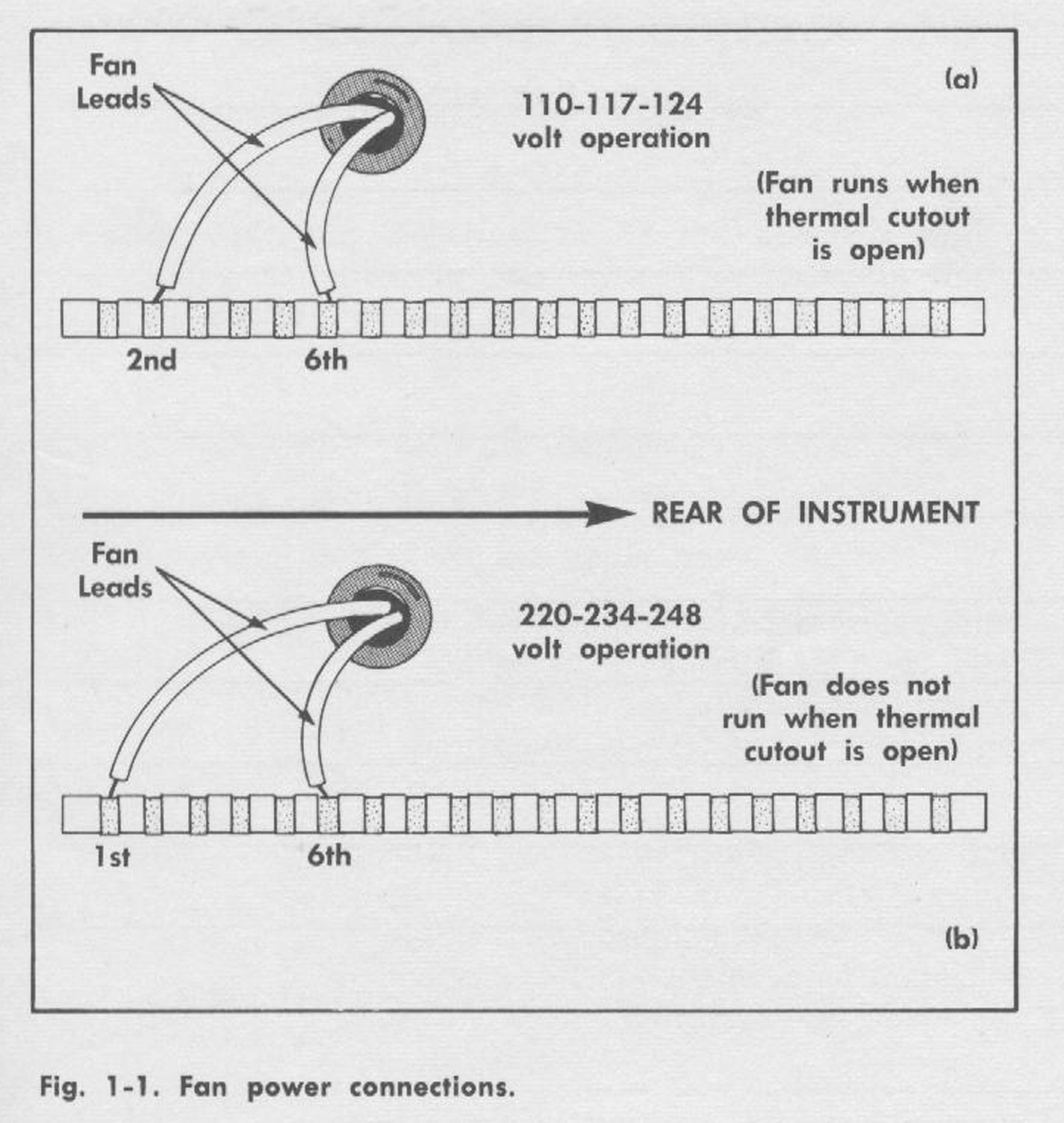 Line Frequency
50 to 60 cycles.
Power Consumption
Maximum of about 600 watts including plug-in unit power
consumption and excluding loads connected to the AUX.
POWER JACK.
Ventilation
Forced filtered air. The self-resetting thermal relay interrupts instrument power in the event of overheating. In
instruments equipped with ac fans, the fan will continue to run during thermal interruption if the instrument is wired tor design-center line voltages of 125 vac and below.
Construction
Four-piece, blue vinyl finished cabinet, aluminum-alloy chassis, and photo-etched, anodized front panel.
Dimensions
Width: 17 inches
Height: 13½; inches
Depth: 233/8 inches
Weight: 62 pounds»
§§§
Il testo prosegue nella quarta parte.
Per consultare le altre schede dedicate a questo oscilloscopio esposto al Museo MITI (su proposta di Fabio Panfili) scrivere “565” su Cerca.
Elaborazioni e testo a cura di Fabio Panfili.
Per ingrandire le immagini cliccare su di esse col tasto destro del mouse e scegliere tra le opzioni.