
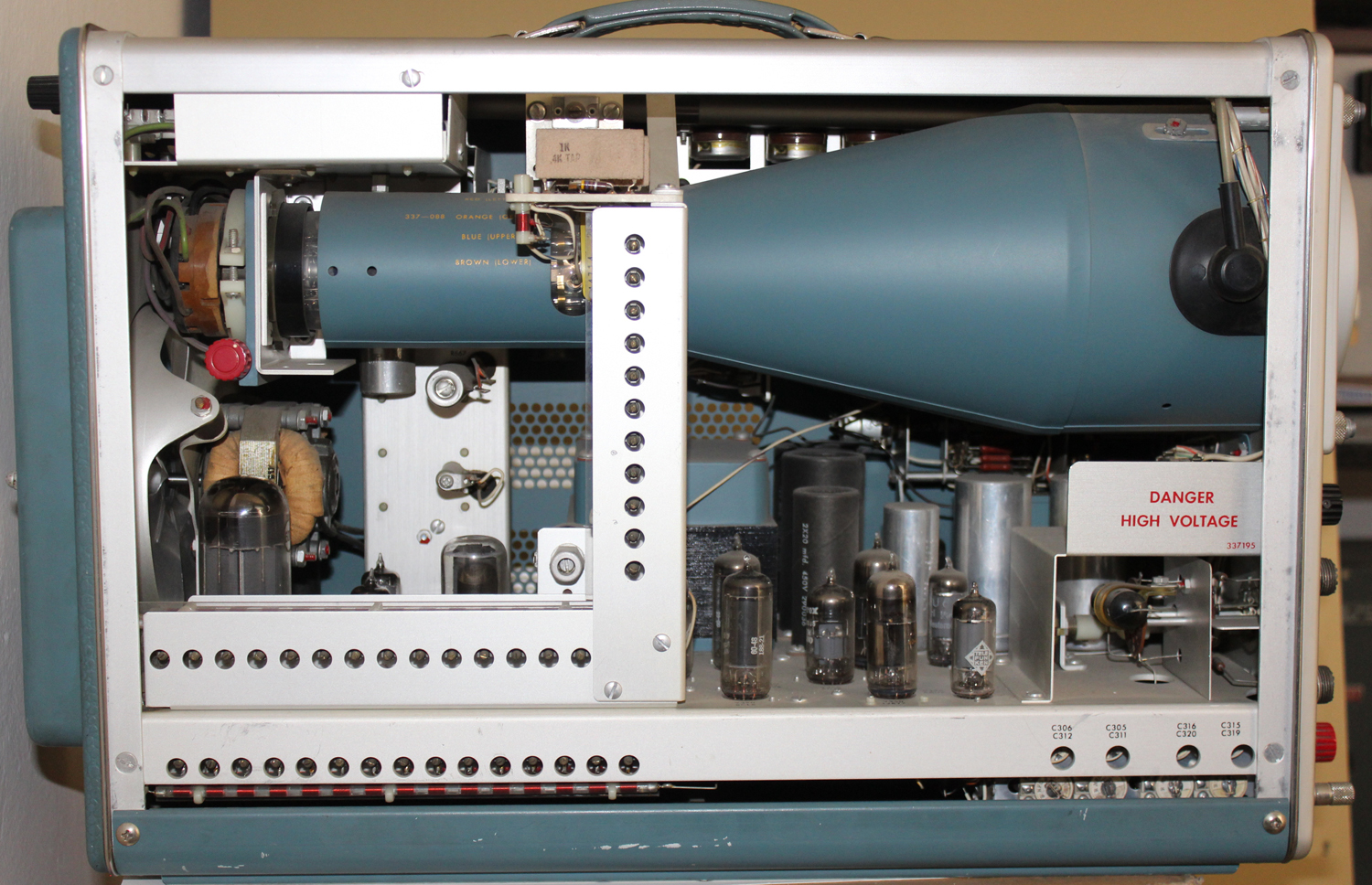
Oscilloscopio a tubo catodico Tektronix Type 515A serial 005869. Quinta parte.
Della Tektronix, Inc. Portland, Oregon, Usa. Nell’inventario D del 1956, in data aprile 1961, al n° 1899 si legge: ”Imp. Silvestar-Milano – Oscilloscopio Tektronix tipo 515A. Destinazione Elettronica. ₤ 840000”.
Il testo continua dalla quarta parte.
§§§
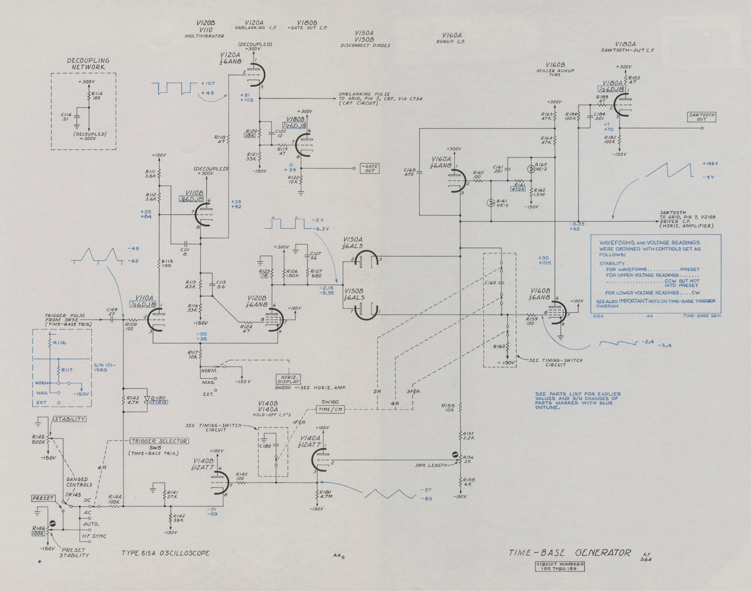
«Schmitt Multivibrator
The dc-coupled multivibrator, shown in the time-base diagram, turns on the time-base generator upon receipt of a negative trigger from the trigger shaper, and holds off subsequent trigger signals until after the sweep is completed. The multivibrator consists of V110A and V120 with both common-cathode and plate-to-grid coupling. Plate-to-grid coupling is by means of a cathode follower.
In the quiescent state V110A is conducting and its plate is down. Cathode-follower V110B holds the grid of V120B below cutoff through voltage divider R115 , R116. Cathode-follower V110B isolates the plate of V110A from the
various loads, and thereby permits a faster
step.
When the negative trigger pulse from the trigger-shaper stage reaches the grid of V110A it is coupled to V120B and V120B starts to conduct. The multivibrator switches quickly to its second state with V120B conducting and V110A cut off. The biases and plate loads are adjusted so that when V110A is conducting, the grid of V120B is held below cutoff, and when V120B is conducting the cathode of V110A is held above cutoff.
There are thus two stable states, in either of which the multivibrator will remain until a signal of the proper polarity and amplitude to the grid of V110A switches it to the other state. To return the multivibrator back to
the quiescent state with V110A conducting, a positive voltage is required at the grid of V110A which is high enough to cause plate current to flow. The positive voltage for returning the multivibrator to its quiescent state is supplied from the time-base generator when it has completed its sweep.
The STABILITY and PRESET controls adjust the grid voltage of V110A near the point of free running.
Time- Base Generator
The time-base generator is a Miller integrator circuit. The circuit includes disconnect diodes V150A and V150B, cathode-follower V160A, timing capacitor C160 and the Miller tube, V160B. In the quiescent state between sweeps, the plates of diodes V150A and V150B rest at -2.5 volts. Very little current flows through V150B to the grid circuit of V160B, and the
grid of V160B rests at -2.5 volts. More current flows through V150A so that its cathode is about .5 volt lower at -3 volts. The timing capacitor, C160, which is connected between these two points, therefore has a charge of
about .5 volt. The grid of cathode-follower V160A is
connected to the plate of Miller tube V160B through neon glow tube B160. The grid of V160A therefore follows the plate changes of V160B but remains 55 volts below the plate. Network C161, R161, improves the risetime of the circuit.
The -2.5 volt bias on the grid of V160B places the tube in the class A region of its operating characteristic, where the plate-to-cathode voltage is inversely proportional to the grid to cathode voltage. The plate rests at about +55 volts. The negative step from the multivibrator to the plates of diodes V150A and V150B lowers the plates below their cathodes
and they no longer conduct. The Miller-tube grid, and the cathode follower are thus released to seek their own voltage levels. The grid of Miller tube V160B, which is returned to
-150 volts through R150, starts negative. When the grid starts negative the plate starts-positive carrying cathode-follower V160A grid and cathode positive. This raises the top end of C160 positive which thus tends to prevent the Miller tube grid from going negative.
The gain of the Miller tube as a class-A amplifier is so high that the plate signal coupled back through charging capacitor C160 keeps the grid voltage constant within a fraction of a volt. Meanwhile, C160 is charging with current through R150 from the -150-volt bus.
Since the grid of V160B remains constant within a fraction of a volt, the current through R150 remains constant, and C160 thus charges at a constant rate. As C160 charges the voltage of the upper end therefore rises linearily.
Any departure from a linear rise of the cathode of cathode follower V160A will result in a change in Miller-tube grid voltage in the direction that will correct for the error. A bootstrap capacitor, C165, increases the plate current in V160B at the higher sweep speeds to help maintain a linear voltage rise.
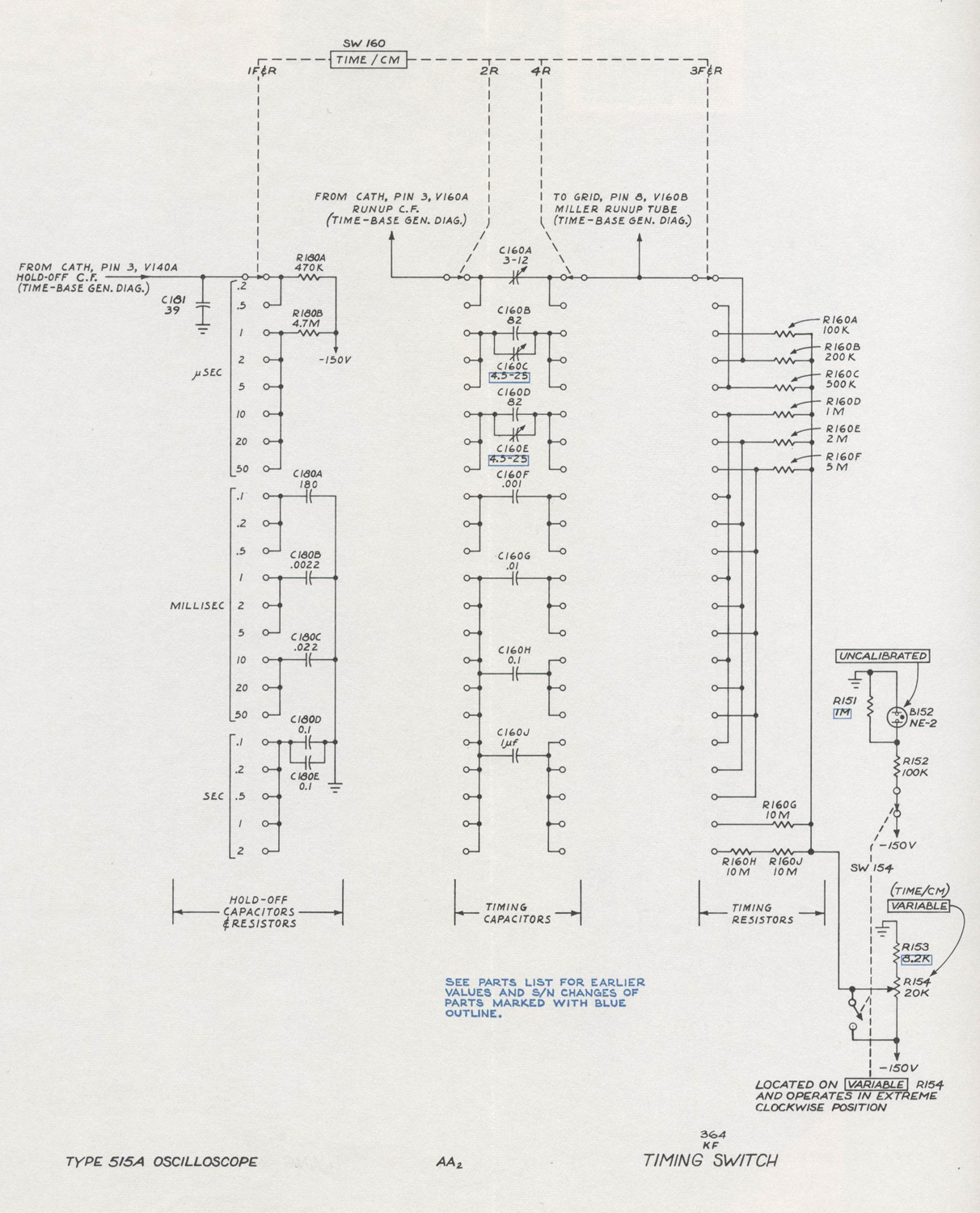
The linear rise of the cathode of V160A is used as the time-base sawtooth. Charging capacitor C160 is selected by means of a step switch, SW155, labeled TIME/CM on the front panel. Charging resistor R150 is also selected by the TIME/CM switch so that both the size of the capacitor being charged and the current charging the capacitor can be selected to cover a wide range of sawtooth slopes.
The cathode of V160A continues to rise linearly until a positive step from the multivibrator, V120B, returns the disconnect diode plates back to their quiescent state raising
the Miller tube grid. When the Miller tube grid rises, its plate drops carrying cathode-follower V160A with it until its cathode clamps again through V150A at the quiescent level of -2.5 volts. The Miller-tube plate will always rest at about +55 volts after the sweep, because, as V150A begins to conduct, its plate drops slightly. This reduced plate voltage allows the Miller-tube grid to go slightly more negative, stopping the fall in plate voltage.
Sawtooth Amplitude
The positive step from multivibrator V120B, which stops the sweep, occurs when a positive voltage is delivered to the grid of multivibrator V110A. The time-base sawtooth is applied to the multivibrator through cathode followers V140A and V140B from a tap on the cathode- load resistor of V160A. This tap is adjustable by means of potentiometer R156, labeled Sawtooth Amplitude, a screwdriver adjustment.
When the voltage of this tap is properly set, the sawtooth will terminate when the spot has passed the right-hand limit of the graticule.
C130 on the grid of V140B retards the return of V140B grid to the quiescent level after the passage of the positive voltage. This prevents any trigger signals from retriggering the multivibrator until all other capacitances in the circuit have had time to reach their quiescent voltage levels. Proper sizes of capacitor C131 are switched with the TIME/CM switch so that more recovery time is permitted for the slower sweep rates and the least necessary recovery time is allowed for the faster sweep rates.
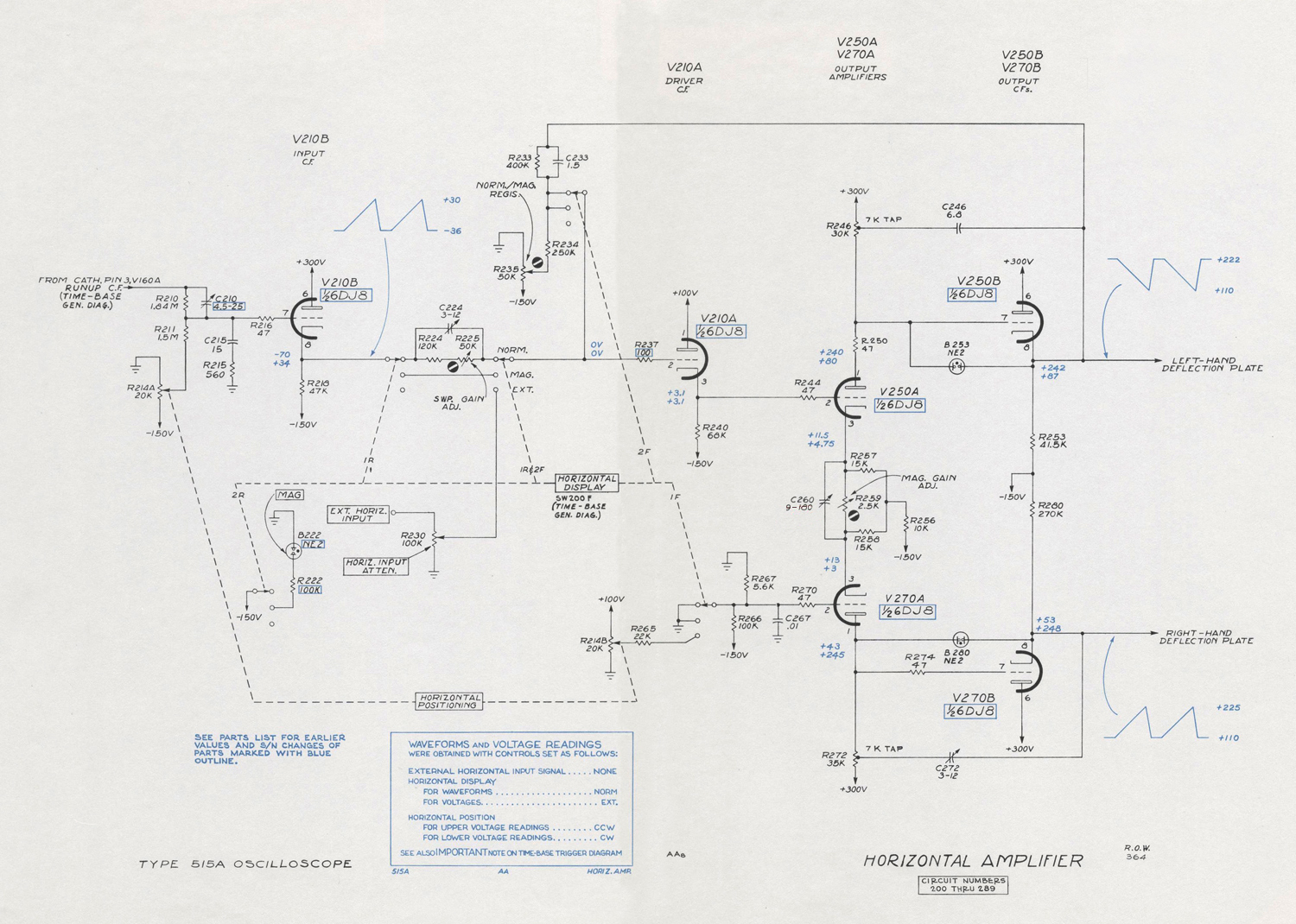
Horizontal Amplifier
The time-base waveform passes through the frequency-compensated positioning network, R210, R211, to the grid of cathode-follower V210B. This cathode follower provides the necessary low impedance to drive the switch capacitances and the second cathode follower, V210A. In the NORM. position of the HORIZ. DISPLAY switch, an attenuation network is inserted between the cathode of the Input C.F., V210B and the Driver C. F., V210A. In the MAG. position of the HORIZ. DISPLAY switch, this attenuator network is bypassed, so that the amplitude of the input signal to the Amplifiers is multiplied by a factor of five. In the EXT position, the HORIZ. DISPLAY switch connects the amplifier to the EXT. HORIZ. INPUT binding post to display the signal applied to this binding post.
Cathode-follower V210A applies the signal to the output amplifier, V250A and V270A.
The output amplifier, converts the signal for push-pull application to the deflection plates. R259 varies the degeneration in the cathode circuits to set the gain of the amplifier. C260 provides high-frequency compensation of the output amplifier by reducing the high-frequency
degeneration. R214B provides horizontal positioning when the HORIZ. DISPLAY switch is in the EXT. position.
The waveform at the plates of the output amplifier is applied to the crt horizontal-deflection plates via cathode followers V250B and V270B. Bootstrap capacitors C246 and C272 increase the current in the output amplifiers at the high sweep rates to improve time-base linearity. Neon diodes B253 and B280 protect the cathode followers from excess grid to cathode voltage when the instrument is first turned on.
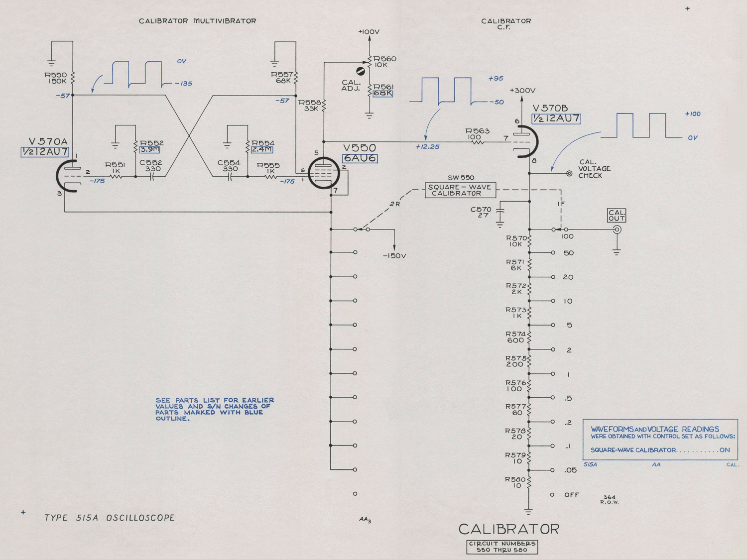
CALIBRATOR
The calibrator is a symmetrical multivibrator with V550A and V550B connected so as to turn cathode-follower V570 on and off as it oscillates. During the negative pulse at multivibrator V550A, the grid of the cathode follower is driven well below cutoff , so the cathode is at ground voltage. During the positive pulse at the multivibrator, the plate is cut off and rests slightly below +100 volts. The voltage of the plate during cutoff is determined by the setting of R560, part of a divider between + 100 volts and ground. R560 is a screwdriver adjustment labeled CAL. ADJ.
Cathode follower V570 has a tapped, calibrated voltage divider for its cathode resistor. When the CAL. ADJ. control is properly set, the cathode-follower cathode is at +100 volts when V510B is cut off. The taps on the divider provide eleven fixed calibrated amplitudes. No internal connection from the calibrator to the vertical-deflection circuits is provided.
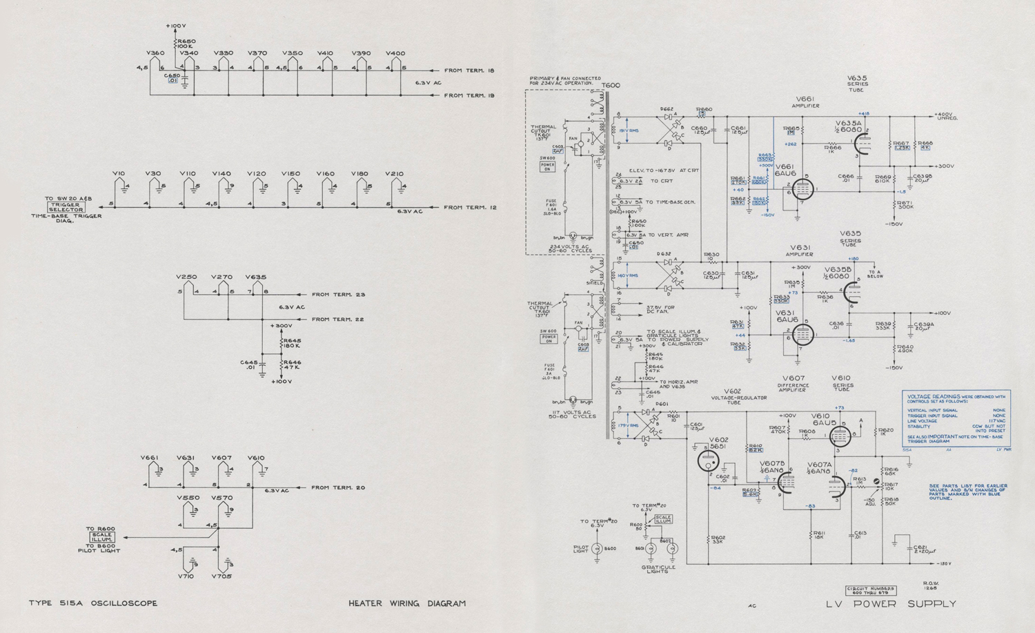
POWER SUPPLY
Transformer
Plate and heater power for the Type 515/515A is provided by a single power transformer, T600. The transformer has two equal 117-volt windings that can be connected either in parallel for 117-volt operation, or in series for 234- volt operation.
Rectifiers
The ac voltage from the high-voltage windings is rectified by bridge-connected full-wave selenium rectifiers.
-150 Volt Supply
All dc voltage furnished by the power supply are regulated with the exception of the +360-volt supply which is used only to supply circuits which are insensitive to voltage variations.
Reference voltage for the regulators is established by means of a gas-diode voltage reference tube, V602. The voltage-reference tube determines the grid voltage of a comparator amplifier, V607, in the -150-volt supply.
The grid potential of V607B is compared with the voltage obtained from a divider, R616, R617, R618, between the -150-volt bus and ground. R617, labeled -150 ADJ., determines the percentage of the total voltage that appears
at the grid of V607A and thus determines the total voltage across the divider.
The voltage difference between the two grids of V607 appears as an amplified error signal at the plate of V607B. The amplified error signal is dc coupled to the grid of the series-regulator tube, V610. This dc-coupled error signal controls the plate resistance of the series regulator tube, changing it in the rightdirection to compensate for any change in output voltage. C613 increases the ac gain
of the feedback loop to reduce the ripple.
The screen of V607B has a small amount of the ripple that exists ahead of the series regulator tube connected to it through R605.
The phase of this ripple is such as to reduce the ripple of the -150-volt bus. This circuit also improves the regulation in the presence of line-voltage variation. R620 bypasses the series tube to reduce the amount of load current through it.
+100-Volt Supply
The -150-volt supply serves as reference voltage for the +100-volt supply. The voltage at the tap on the voltage divider, R639, R640, is applied to the grid of V631. The error signal is amplified in V631 and applied to the grid of V635B, the series-regulator tube, R633, at the screen of V631, reduces ripple and improves the regulation of the supply. C636 increases the ac gain of the feedback loop.
+300-Volt Supply
Rectified voltage from terminals 8 and 9 of the power transformer is added to the voltage supplying the +100-volt regulator to provide about 400 volts for the +300-volt regulator and other points in the instrument which do not ned a regulated voltage. The +300-volt circuit is similar in operation to the + 100-volt regulator.
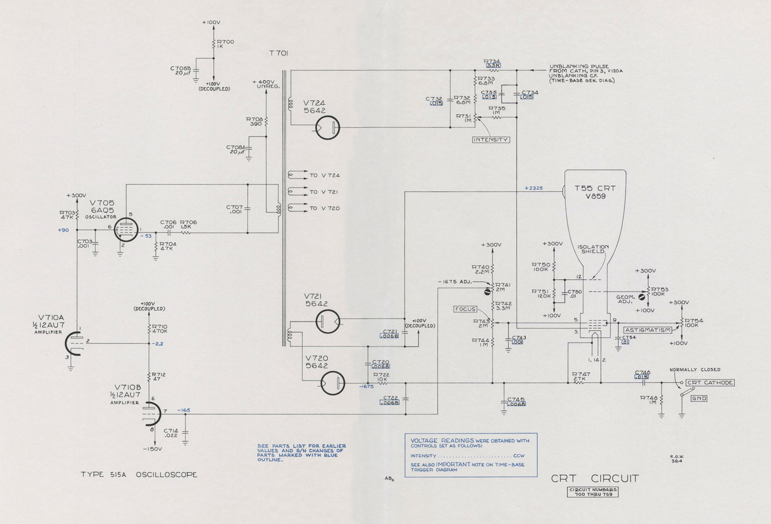
CRT CIRCUIT
High-Voltage Supply
Accelerating voltage for the cathode-ray tube is obtained by rectifying a 60-kc voltage produced by a vacuum—tube oscillator. V705 is the oscillator tube with the primary of T701 serving as a tapped inductor. Rectifier V720 supplies -1675 volts to the crt cathode and V721 supplies +2325 volts to the post-acceleration helix to provide a total acceleration voltage of 4000 volts.
High-Voltage Regulator
A divider from the crt cathode to the +300-volt bus applies a sample of the negative accelerating voltage to the grid of V710B. R741 varies the voltage at the tap to adjust the high voltage. The -150-volt supply,connected to the cathode of V710B, serves as a reference voltage. The amplified error signal at the plate of V710B is applied to the grid of the shunt regulator tube, V710A. The shunt regulator tube determines the screen voltage of the oscillator tube and thus controls the oscillator output voltage.
If, for example, the output voltage becomes too high, the regulator reduces the voltage on the screen of the oscillator tube. The output voltage of the oscillator decreases and the output voltage is corrected.
Unblanking
The crt control-grid voltage is produced by a winding and rectifier, V724, similar to the cathode supply but insulated from it. The positive end of the control-grid supply is connected to the unblanking cathode follower.
When the unblanking pulse is produced at the cathode of the unblanking cathode follower, it drives the whole grid-voltage supply with it so that the pulse appears at the crt grid. Since this is a dc connection, the unblanking pulse can have any duration with no change in grid voltage. The INTENSITY control, R731, varies the bias on the grid to determine trace brightness.
CRT Geometry Control
The second-anode voltage required for best linearity at the extremes of deflection may vary somewhat between tubes. R753, labeled GEOM. ADJ. on the chassis, permits this
voltage to be adjusted».
§§§
Per consultare le parti dedicate a questo oscilloscopio scrivere: “515A” su Cerca.
Foto di Claudio Profumieri, elaborazioni, ricerche e testo a cura di Fabio Panfili.
Per ingrandire le immagini cliccare su di esse col tasto destro del mouse e scegliere tra le opzioni.
.