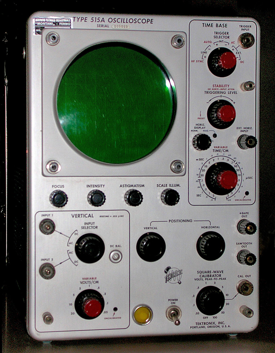
Oscilloscopio a tubo catodico Tektronix Type 515A serial 005869. Terza parte.
Della Tektronix, Inc. Portland, Oregon, Usa. Nell’inventario D del 1956, in data aprile 1961, al n° 1899 si legge: “Imp. Silvestar-Milano – Oscilloscopio Tektronix tipo 515A. Destinazione Elettronica. ₤ 840000”.
Il testo continua dalla seconda parte.
§§§
«Stability
The STABILITY control adjusts the bias level on a multivibrator in the time-base generator near the level at which the sweep will free-run. Three principal settings of the STABILITY control are used; the first setting is with the control advanced to the right, past the point where the generator free-runs; second, retarded to the left just past the point where free-running ceases; and third, retarded all
the way left to make the generator inoperative.
The second setting is duplicated by an internal circuit when the STABILITY control is rotated to the PRESET position.
When the time-base generator free-runs, the sawtooth waveforms are produced at a repetition rate determined by the generator circuit itself. The STABILITY control varies
this repetition rate slightly. In the second, or triggered, position of the STABILITY control the time-bas; generator does not run until a trigger pulse is received at which time one sawtooth waveform is produced and the generator waits for the next trigger pulse.
This is also the case when the STABILITY control is set at PRESET.
For synchronized operation of the time-base generator, as used in the H F SYNC position, set the STABILITY control to the advanced position so that the generator just free-runs,
and keep it to the right of this point while adjusting its point to synchronize the time base.
For all triggered operation except AUTO., the STABILITY control should be retarded to the left of the free run point or set to the PRESET position (S/N 1001-up).
General-Purpose Triggering
For most average triggering applications the AUTO. mode of triggering is the easiest to use. Only one control need be adjusted and after it is once set the sweep will trigger
satisfactorily on a wide variety of waveforms and over a wide range of sweep speeds without resetting. When the STABILITY control is set properly there will always be a trace on the screen, whether a signal is present ornot, unless the trace is positioned off the screen vertically. This feature is especially valuable if the probe is being moved from
one point to another in a circuit under test.
To use the AUTO. mode, set the red TRIGGER SELECTOR knob to AUTO. A horizontal trace should appear immediately. A stable display should be obtained on most signals within the range of 60 cycles to 2 megacycles when using this mode.
For any application within the frequency range from 60 cycles to about 5 megacycles where the display is unstable on AUTO., the AC mode can be used. To use this mode of
triggering proceed as follows:
1 . Set the red TRIGGER SELECTOR knob to AC.
2. Set the STABILITY C0ntI’01 t0 the PRESET position (counterclockwise S/N 101-1000).
3. Adjust the TRIGGERING LEVEL control for stable triggering. The procedure outlined above will provide
stable triggering for most applications. However, with some triggering waveforms, it may be necessary to manually set the STABILITY control. This is done as follows:
1. Set the red TRIGGER SELECTOR knob to AC.
2. Turn the TRIGGERING LEVEL control counterclockwise to the stop.
3. Advance the STABILITY control clockwise until the time-base generator free-runs then back it off just past the point where the sweep stops.
4. Turn the TRIGGERING LEVEL control clockwise until stable triggering occurs. With this same control you can now select the point or level at which triggering occurs. Triggering should occur near the 0 mark.
Low-Frequency Triggering
For waveforms having a slow rise and a repetition rate of less than 60 cps, the DC triggering mode is best.
To use this mode of triggering, proceed as follows:
1. Set the red TRIGGER SELECTOR knob to DC.
2. Set the STABILITY control to the PRESET position (counterclockwise S/N 101-1000).
3. Adjust the TRIGGERING LEVEL control for stable triggering. The procedure outlined above will provide
stable triggering for most applications. However, with some triggering waveforms, it may be necessary to manually set the STABILITY control. This is done as follows:
1. Set the TRIGGER SELECTOR red knob to DC.
2. Turn the TRIGGERING LEVEL control counterclockwise to the stop.
3. Advance the STABILITY control clockwise until the time-base generator free-runs then back it off just past the point where the sweep stops.
4. Turn the TRIGGERING LEVEL control clockwise until stable triggering occurs. With this same control you can now select the point or level at which triggering occurs.
Triggering should occur near the 0 mark if the trace is centered. Since the AC mode is more sensitive than the DC mode above 60 cps and is not affected by the positioning controls, it is superior to the DC mode, above 60 cps. However, the DC mode can be used up to about 5 mc.
High-Frequency Synchronization
For stable triggering it is necessary for the trigger circuits to have a frequency response considerably in excess of the frequency of the waveform being displayed. At about five
megacycles the efficiency of the trigger circuits is reduced and the H F SYNC mode becomes the best method of synchronizing the trace.
To use the H F SYNC mode simply advance the STABILITY control until the time base free-runs and then continue to advance it until the time base locks in with the signal. The polarity markings on the TRIGGER
SELECTOR switch have no significance in this mode, and the TRIGGERING LEVEL control is not used.
Triggering on Complex Waveforms
When the waveform under observation is complex there may be several points on the waveform where ordinary triggering circuits may tend to trigger. As a result, the trace
may be unstable. This instability may be encountered occasionally with the AUTO. mode of triggering. The AC and DC triggering modes allow the level on a waveform, at which triggering occurs, to be selected by the TRIGGERING LEVEL control. Thus the LEVEL control can be set so that only one point on the waveform is of sufficient amplitude to trip the triggering circuits. This point can be located by setting the controls as for the AC or DC triggering modes and then moving the TRIGGERING LEVEL control away from the 0 mark in either direction
until the trace becomes stable.
Trigger-Signal Source
For most normal triggering applications the INT. trigger source is most convenient. In the INT. positions of the TRIGGER SELECTOR switch the triggering signal is obtained from the vertical amplifier. If an external trigger source is available it is often convenient to use the EXT. positions of the TRIGGER SELECTOR switch. An external
trigger source is particularly useful if the amplitude of the signal under observation is changing or if the probe is being moved from point to point in a circuit.
The LINE positions of the TRIGGER SELECTOR switch permit stable triggering at the line frequency. These positions are useful when displaying almost any function
that is synchronized with the line.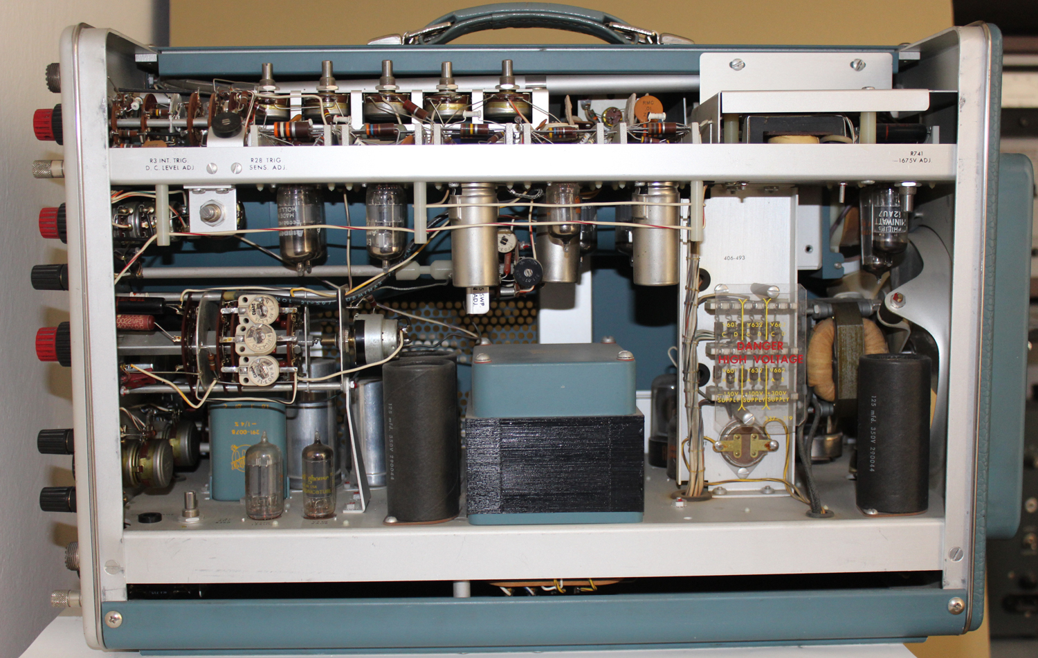
 TIME-BASE OPERATION
General
The time-base generator produces the sawtooth waveform which is used to move the beam across the crt. The TIME/CM controls vary the slope, but not the amplitude, of this waveform, and thus determine the sweep rate
without affecting the length greatly.
The horizontal amplifier amplifies the sawtooth waveform and applies it to the crt deflection plates. The HORIZ. DISPLAY switch increases the gain of the amplifier five times in the MAG. position. In this position the display
is spread over the equivalent of five screen diameters.
Sweep Rule
The TIME/CM controls determine the sweep rate of the horizontal trace. The TIME/CM of horizontal deflection is indicated by the black numbers when the HORIZ. DISPLAY switch is in the normal position and by the
blue numbers when it is in the MAG. position.
These numbers are correct only when the red VARIABLE control is completely clockwise.
The UNCALIB RATED light indicates when the time base is not calibrated for this reason. The VARIABLE control has a range of about 2 · 1/2 to 1. [?? N.d.R.]
Magnifier
The HORIZ. DISPLAY switch increases the horizontal-amplifier gain five times in the MAG. position expanding the time base so that the center one-fifth of the trace fills
the graticule. The MAG. light is energized when the HORIZ. DISPLAY switch is turned to the MAG. position. Any portion of the trace may be positioned on the screen with the HORIZONTAL POSITIONING control. If
the VARIABLE control is fully clockwise the magnified sweep rate is indicated by the blue numbers at the TIME/CM switch.
External Horizontal Input
When the HORIZ. DISPLAY switch is in the EXT. position, the horizontal amplifier is connected to the EXT. HORIZ. INPUT binding post. The STABILITY control serves as an
attenuator for signals applied to this bindingpost.
VERTICAL-AMPLIFIER OPERATION
Probes
The P6017 probe furnished with this instrument has a 10 – to – 1 attenuation ratio. Be sure to check the adjustment of the probe regularly and before making critical measurements. If the compensation is incorrect the frequency response will be affected. Touch the probe
tip to the calibrator output connector and display several cycles of the calibrator waveform.
If the top and bottom of the displayed square wave are not flat, adjust the trimmer capacitor located inside the probe compensator box to achieve correct square-wave response.
Input Connections
Be careful that the external circuitry does not cause deterioration of the waveform when you make connections to the INPUT connectors.
Improper termination of cables may cause ringing or loss of frequency response. If you use unshielded leads keep them as short as possible.
Two cables or probes can be connected to the oscilloscope at once. You can then select the signal on either cable with the INPUT SELECTOR switch. However, if one signal
is very much larger than the other, some crosstalk may occur and the cable having the larger signal should be disconnected.
Coupling
It is sometimes unnecessary or undesirable to display the dc level of the waveform. In the two AC positions of the INPUT SELECTOR switch, a capacitor in series with the input blocks the dc component of the waveform so that only the ac component is displayed.
Deflection Sensitivity
The VOLTS/CM switch inserts frequency-compensated attenuators ahead of the amplifier. The VARIABLE control provides continuous adjustment of the deflection sensitivity between the values indicated by the VOLTS/CM switch.
The VARIABLE control must be clockwise against the stop for the sensitivity to be as indicated by the VOLTS/CM switch. The red UNCALIBRATED light indicates when the
VARIABLE control is not fully clockwise.
DC Balance Adjustment
After the oscilloscope has been in use for a period of time you will notice that the trace will change position as the VARIABLE control is rotated. This is caused by tube aging and the resultant shift in operating potentials. To correct this condition rotate the VARIABLE control back and forth and adjust the DC BAL control until the trace position is no longer affected by rotation of the VARIABLE control.
 AUXILIARY FUNCTIONS
Square-Wave Calibrator
The square-wave calibrator provides a source of square waves of known amplitude at about 1000 cycles. The outout impedance varies with the voltage but is as high as 5,000 ohms.
Be sure the load impedance you connect to the CAL. OUT connector does not change the output voltage.
Truce-Brightness Modulation
To couple markers or other signals into the crt cathode for brightness information, disconnect the ground strap at the rear of the instrument and connect the signal to the CRT CATH. binding post.
Graticule Illumination
The graticule lighting control, labeled SCALE ILLUM., can be adjusted to suit the lighting conditions of the room. The graticule can be mounted in either of two positions rotated
180 degrees from each other. In one position the illumination is colored red and, in the other position, white. The white will reproduce well photographically.
A green light filter is supplied which can be used for increased contrast. Normally this filter should be mounted next to the crt screen so it does not block the light from the graticulelines.
Direct Connection to Deflection Plates
Connections can be made directly to the deflection plates by removing the cabinet on the left side. The two pins on the left-hand side of the crt neck are the vertical deflection
plates. To avoid distortion, the average dc potential on these plates should be between 150 and 200 volts. Unless dc coupling is required, connect coupling capacitors in series
with the leads to the deflection plates and connect one-megohm resistors from the deflection plates to the leads from the delay line.
With this connection the plates are maintained at the proper operating potential and positioning control is retained by the front-panel controls.»
§§§
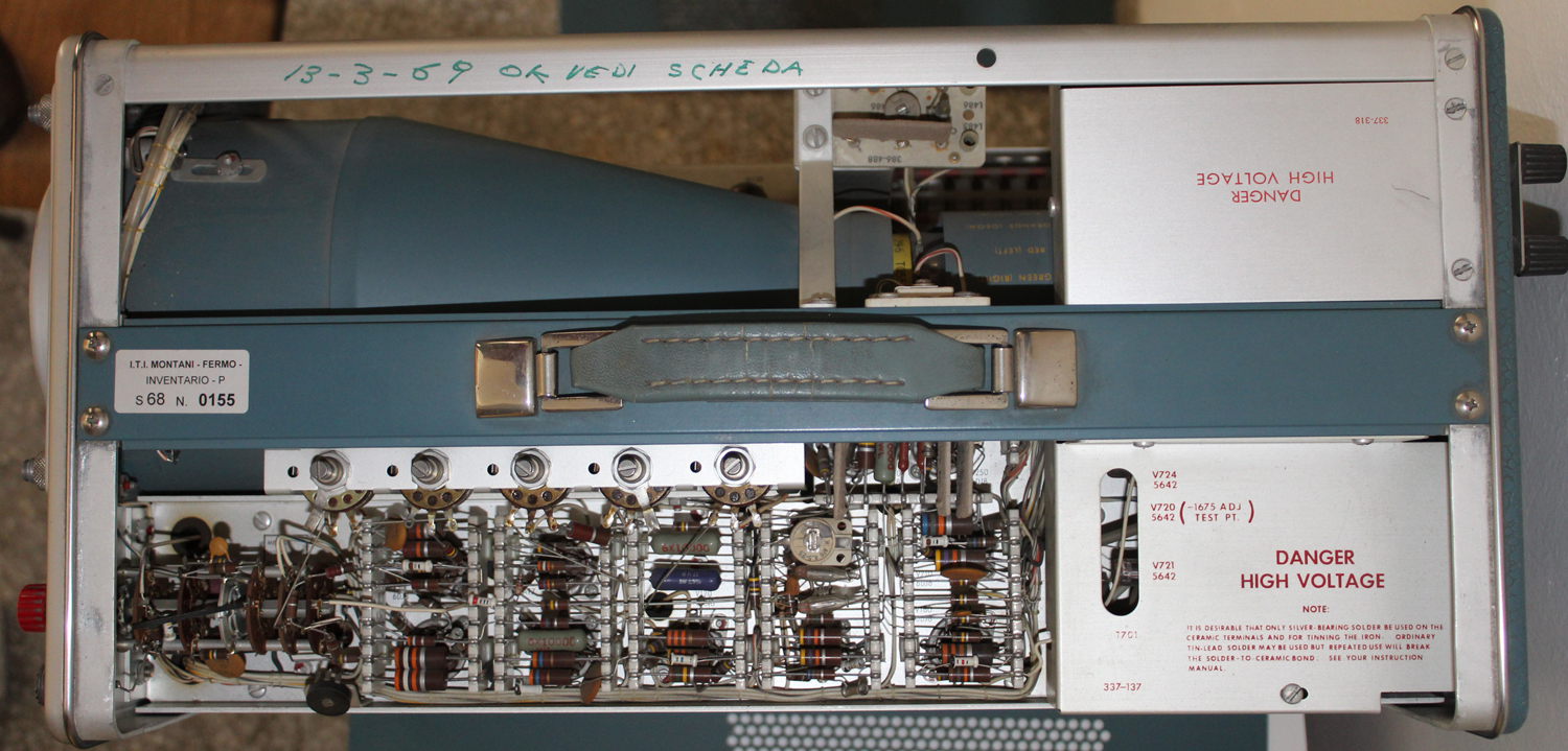
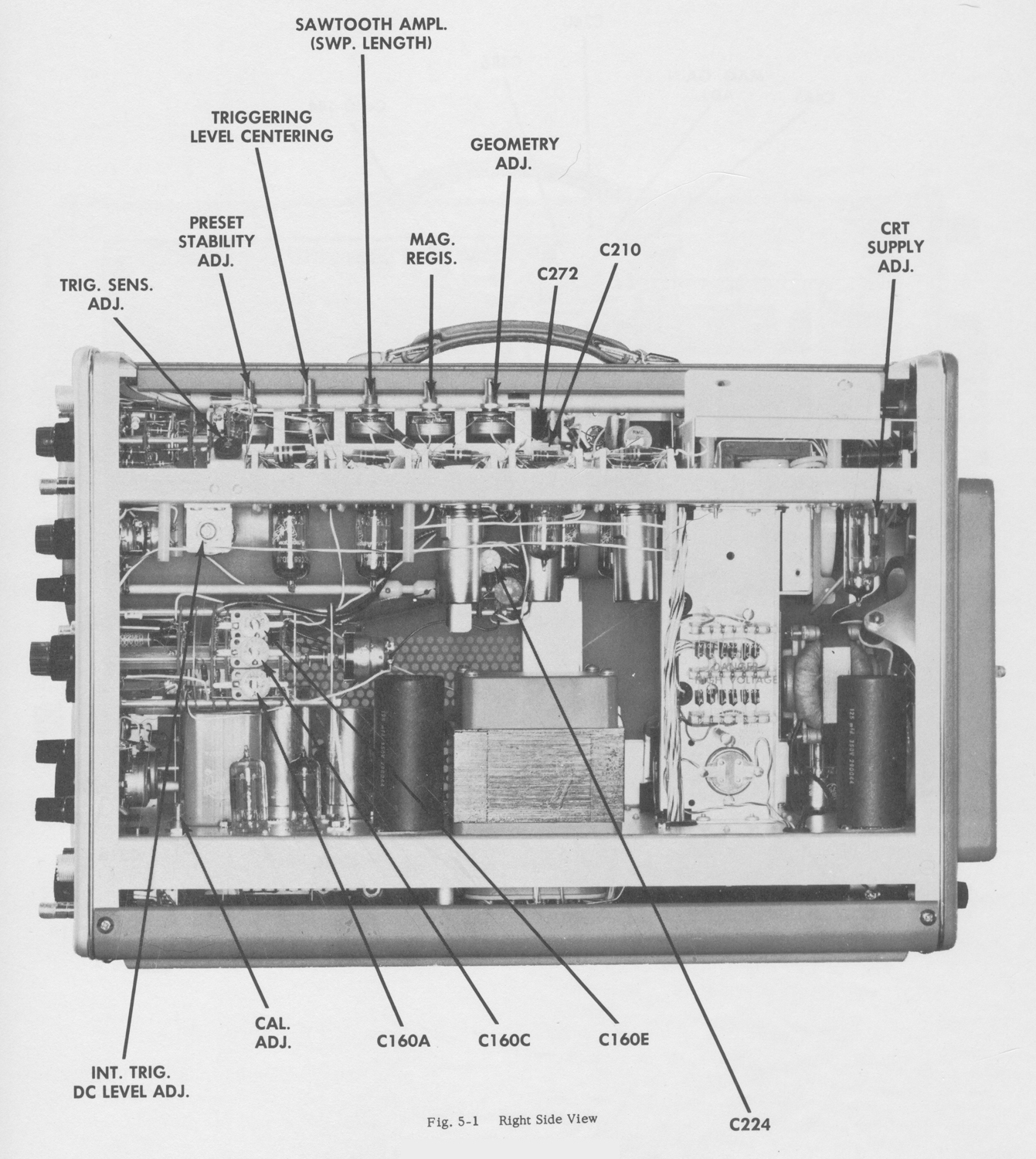
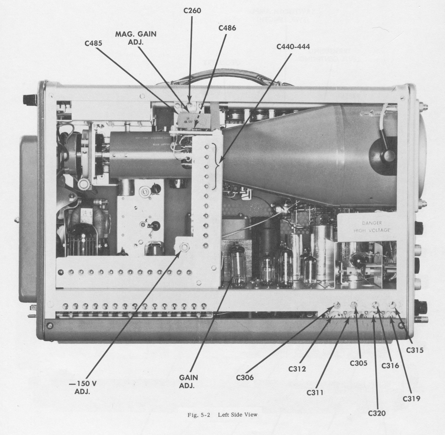
Le due figure sono tratte dal capitolo MAINTENANCE che abbiamo omesso.
Il testo prosegue nella quinta parte.
Per consultare le altre schede dedicate a questo oscilloscopio scrivere: “515A” su Cerca.
Foto di Claudio Profumieri, elaborazioni, ricerche e testo a cura di Fabio Panfili.
Per ingrandire le immagini cliccare su di esse col tasto destro del mouse e scegliere tra le opzioni.