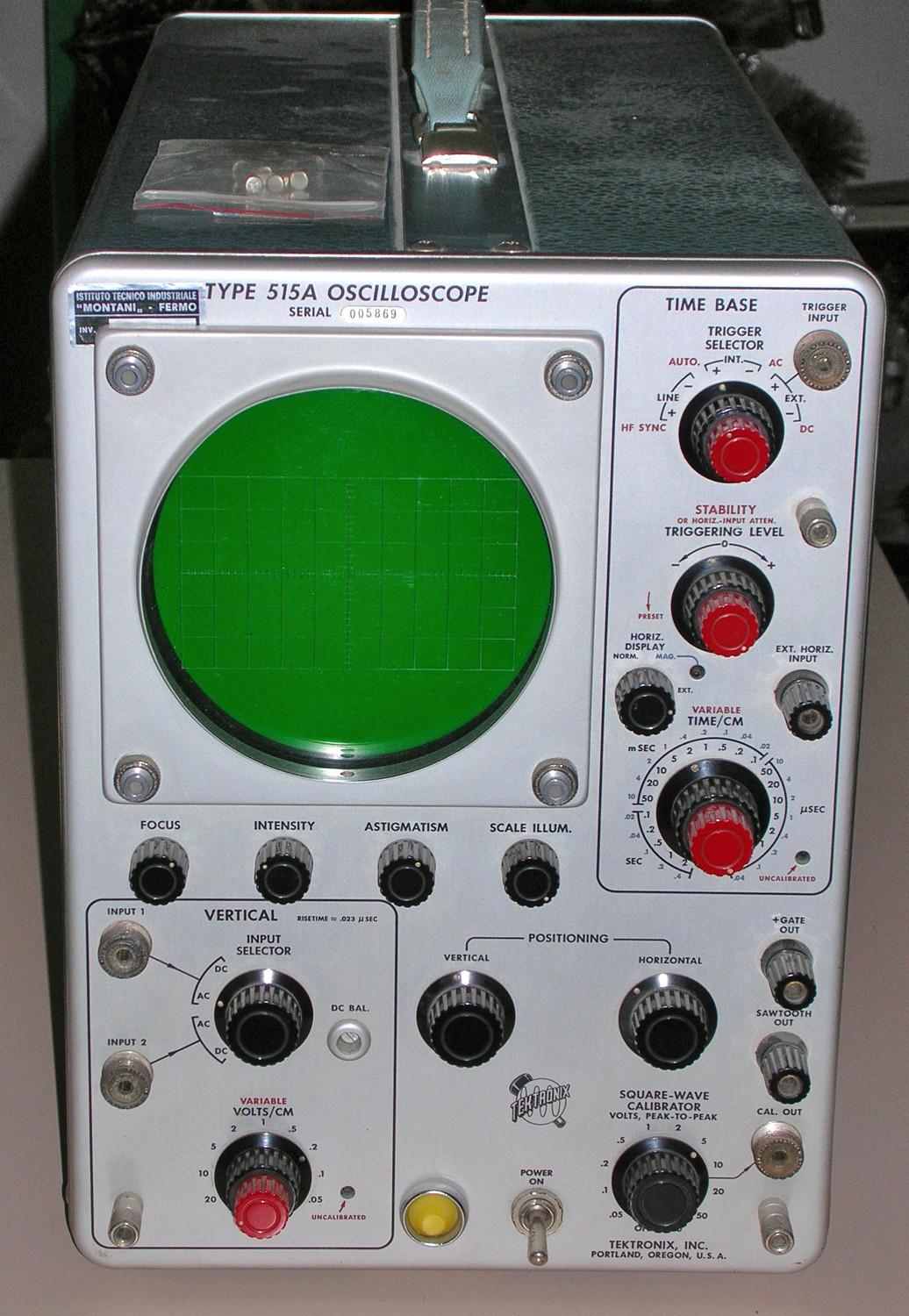
Oscilloscopio a tubo catodico Tektronix Type 515A serial 005869. Seconda parte.
Della Tektronix, Inc. Portland, Oregon, Usa. Nell’inventario D del 1956, in data aprile 1961, al n° 1899 si legge: “Imp. Silvestar-Milano – Oscilloscopio Tektronix tipo 515A. Destinazione Elettronica. ₤ 840000”.
Il testo continua dalla prima parte.
§§§
«SECTION II
OPERATING
INSTRUCTIONS
General information
The Type 515/515A Oscilloscopes are extremely versatile instruments, adaptable to a great number of applications. However, to make use of the full potentialities of the instrument, it is necessary that you understand completely the operation of each control. This portion of the Operators Manual is intended to provide you with the basic information that you require. If you are familiar with other
Tektronix oscilloscopes, you should have very little difficulty in understanding the operation of the 515/515A, since the function of many of the controls is the same as the function of corresponding controls in other Tektronix
instruments.
Cooling
A fan maintains safe operating temperature in the Type 515/515A Oscilloscope by circulating air through a filter and over the rectifiers and other components. The instrument must therefore be placed so the air intake is not
blocked. The air filter must be kept clean to permit adequate air circulation. lf the interior temperature does rise too high for some reason, a thermal cutout switch will disconnect the power and keep it disconnected until the temperature drops to a safe value.
Power Requirements
The regulated power supplies in the Type 515/515A will operate with line voltages from 105 to 125 volts or from 210 to 250 volts.
For maximum dependability and long tube life the voltage should be near the center of this range.
Voltages outside of these limits may cause hum or jitter on the trace. Be sure the line voltage is correct if indications such as these are present.
Unless tagged otherwise, this oscilloscope is connected at the factory for 117 – volt operation. For 234-volt operation , refer to the Maintenance section of this manual for proper transformer connections.
FIRST-TIME OPERATION
Control Settings
The following procedure will help you get a trace on the screen and become familiar with some of the controls.
Connect the line cord to a source of 117- volt 50 to 60 cycle power, and set the front-panel controls as follows:
FOCUS Centered
INTENSITY Counterclockwise (CC W)
ASTIGMATISM Centered
POWER ON
INPUT SELECTOR INPUT 1, DC
VOLTS/CM 5
(black knob)
TRIGGER SELECTOR
black knob + INT
red knob AUTO
TRIGGERING Counterclockwise
LEVEL
STABILITY PRES ET (CCW S/N
(red knob) 101-1000)
HORIZ. DISPLAY NORM.
TIME/CM .5 MILLISEC
VERTICAL Center
POSITIONING
HORIZONTAL Center
POSITIONING
CALIBRATOR 10
Connect a lead from the CAL. OUT connector to the INPUT 1 connector. If the tubes have had time to warm up, turn the INTENSITY control clockwise until a trace is visible on the screen. Adjust the FOCUS, ASTIGMATISM
and INTENSITY controls to produce a sharp trace of comfortable brightness.
The two POSITIONING controls will move the trace vertically and horizontally as necessary to position the display where you want it on the crt screen.
Triggering Modes
If you have not had previous experience with the type of trigger controls used on this oscilloscope, the calibrator waveform is a good one to practice with. A few minutes
spent on trying the triggering modes described below will be time well spent in terms of future operating convenience.
Auto
The triggering method used in the preceding example is the AUTO. (automatic) mode of operation. It is the simplest mode of triggering.
There are no front-panel controls to be adjusted when using this mode. If the signal is removed from the input connector, the sweep will continue, but at a reduced repetition rate. This provides a visual indication that the signal has been removed and the sweep and triggering
circuits are operating.
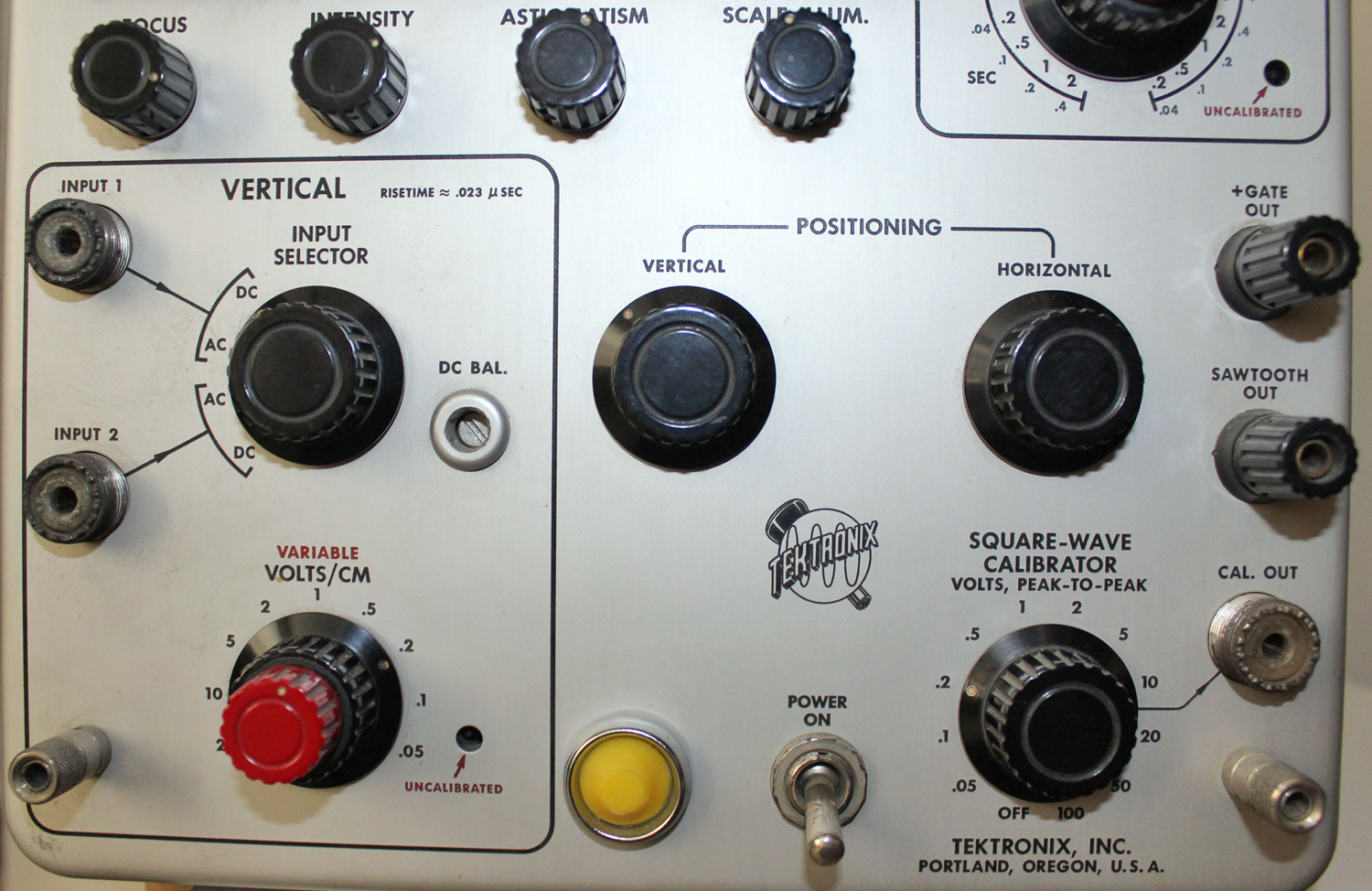
FUNCTIONS OF CONTROLS AND CONNECTORS
CRT Controls
FOCUS Control to adjust the beam for maximum
sharpness of the trace.
INTENSITY Control to vary the brightness of the trace.
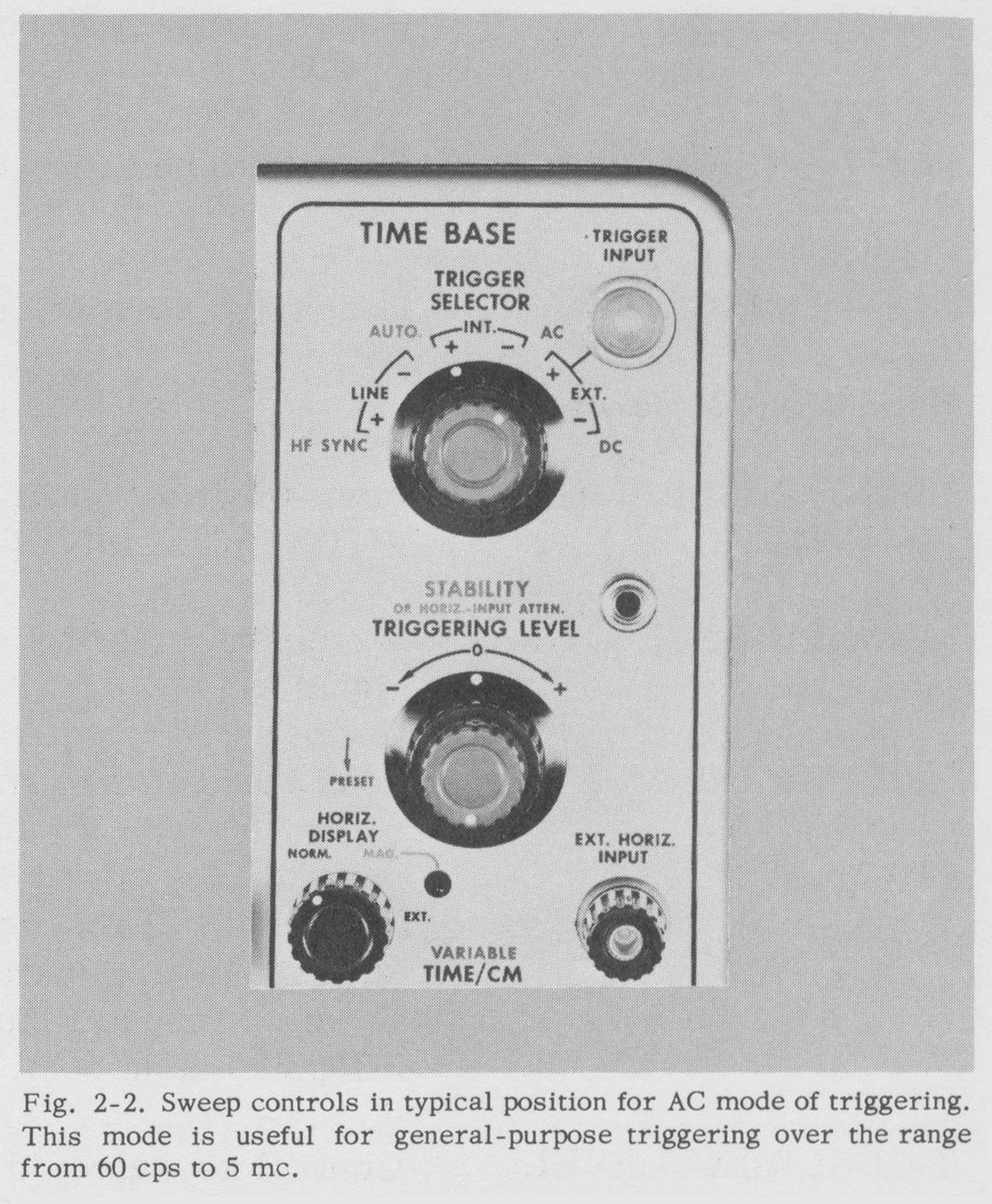
AC
Now try the AC mode of triggering. Turn the red TRIGGER SELECTOR knob to AC. Advance the TRIGGERING LEVEL control clockwise until you get a stable trace. There
may be a considerable range over which you get a stable trace. The start of the trace will move up and down the edge of the square wave over this range. Notice that the trace
starts on the up-going part of the calibrator square wave.
Now turn the black TRIGGER SELECTOR switch to the -INT position and readjust the TRIGGERING LEVEL control to get a stable trace again. Notice now that the trace starts on the down-going portion of the square wave
and that the position of the start can again be changed somewhat with the level control.
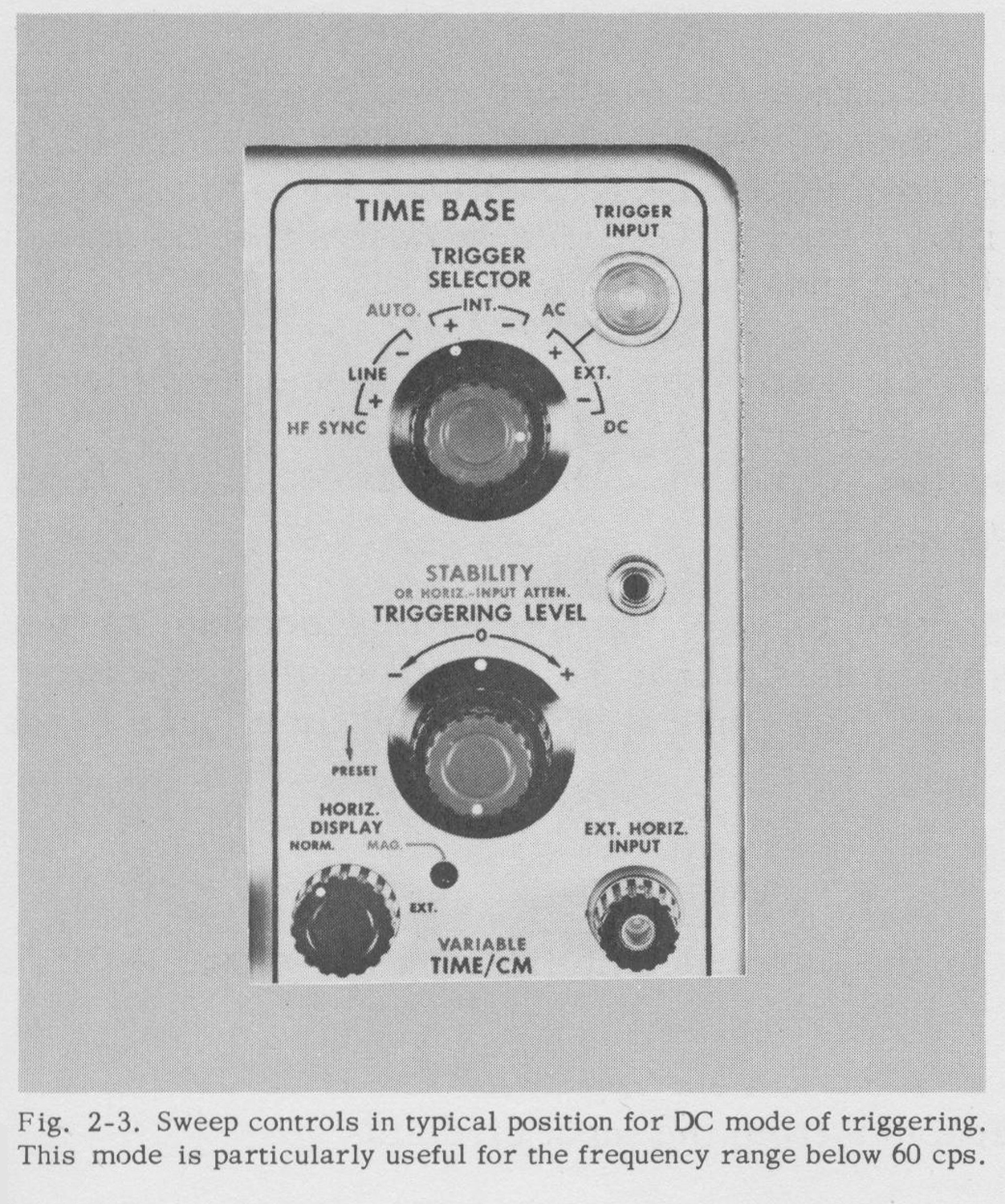
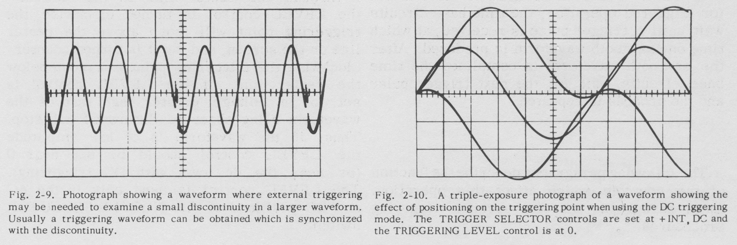
DC
Turn the red TRIGGER SELECTOR knob to If necessary adjust the TRIGGERING LEVEL control for stable triggering. Move the trace vertically on the screen with the
VERTICAL POSITIONING control and note that triggering occurs at a vertical level on the screen selected by the LEVEL control, and that the triggering point changes relative to the waveform as the waveform is positioned
vertically. This effect will be more noticeable if you look at a low-frequency sine wave.
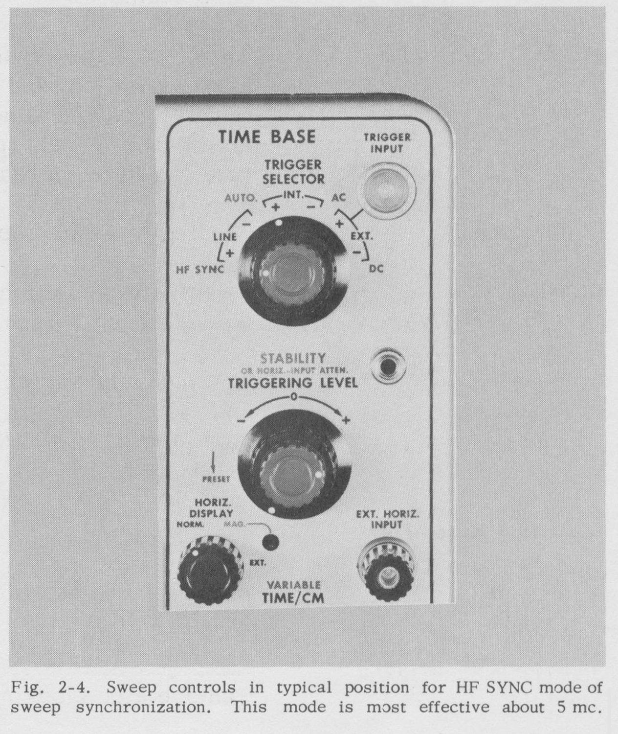
H F Sync
The H F SYNC position of the TRIGGERING SELECTOR switch is primarily for signals having a repetition rate in excess of five megacycles. In this position the time base
will trigger poorly, if at all, on the calibrator waveform. To stabilize the display of a high-frequency signal, simply advance the STABILITY control clockwise until a stable trace is obtained.
The LEVEL control is not used in the H F SYNC mode.
FUNCTIONS OF CONTROLS AND CONNECTORS
CRT Controls
FOCUS Control to adjust the beam for maximum sharpness of the trace
INTENSITY Control to vary the brightness of the trace.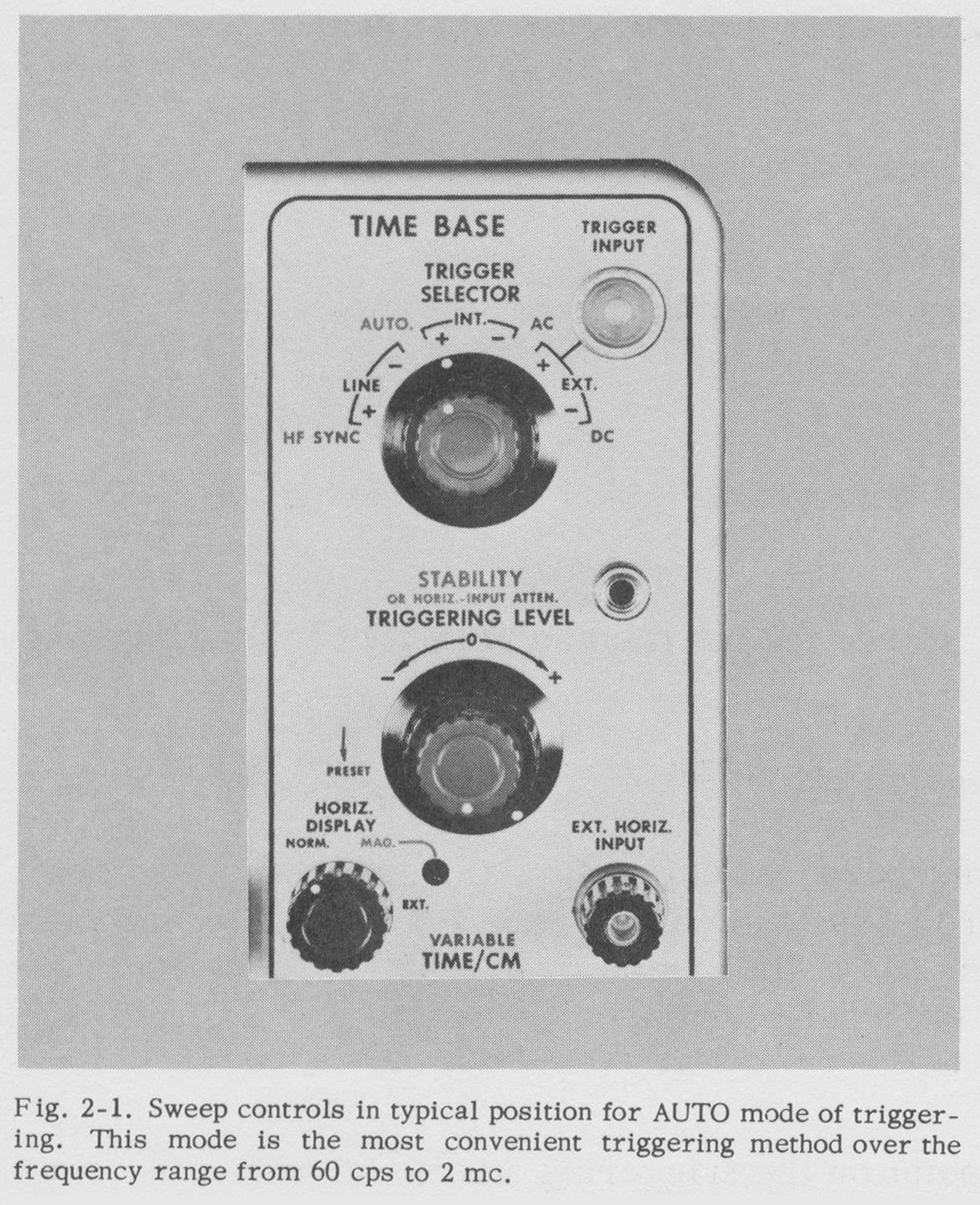
 ASTIGMATISM Control used in conjunction with the FOCUS control to adjust the
beam for maximum sharpness of the trace.
SCALE ILLUM. Control to vary the brightness of the graticule illumination.
VERTICAL
POSITIONING Control to position the trace vertically.
HORIZONTAL
POSITIONING Control to position the trace horizontally.
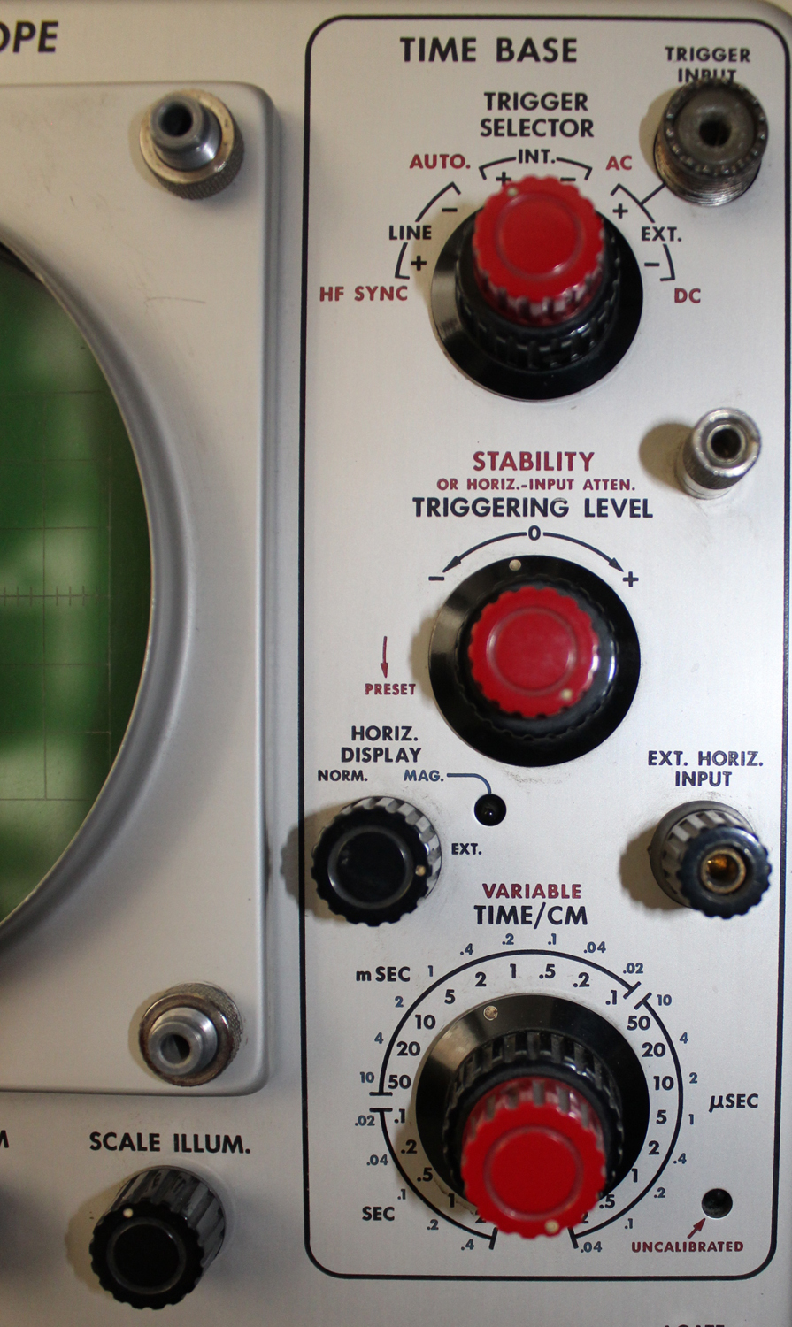
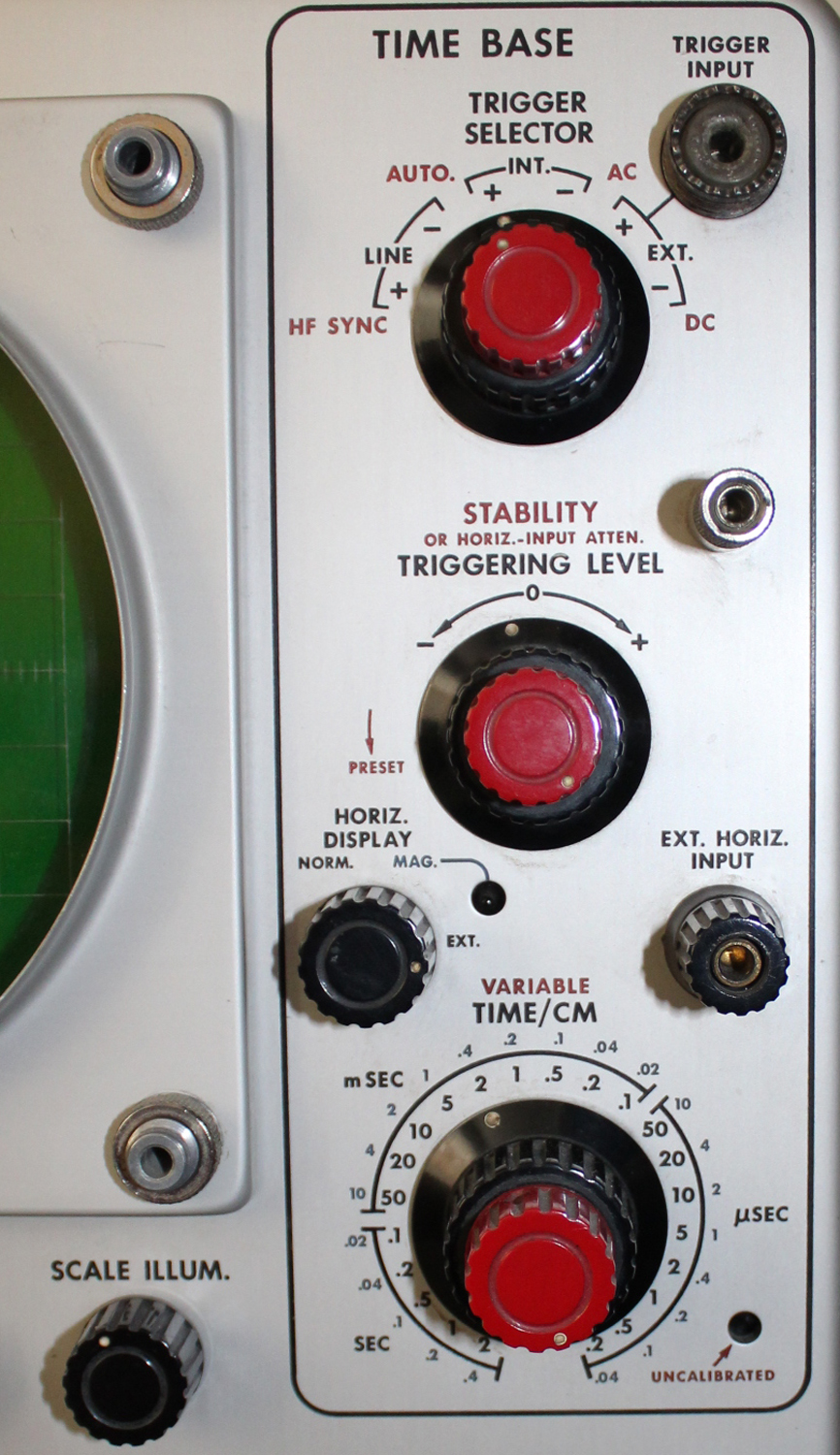
Time-Base Generator
TRIGGER SELECTOR (red knob) Four-position switch to select four kinds of triggering: H F SYNC- AUTO, AC and DC.(red knob)
TRIGGER SELECTOR (black knob) Six—position switch to select the source and polarity of the triggering signal.
TRIGGER INPUT Coax connector to triggering circuits.
STABILITY Control to adjust time-base circuits for triggered or recurrent operation. This control has a PRESET position suitable for most triggering applications (S/N 1001-up). This control also function as an attenuator for external signals connected to the EXT. HORIZ. INPUT binding post.
TRIGGERING LEVEL Control to select the point on the triggering waveform where the time base begins.
HORIZ. DISPLAY Three-position switch to increase the sweep rate five times in the
MAG. position and to connect the horizontal amplifier to the EXT.
HORIZ. INPUT binding post in the EXT. position. When this control is in the MAG. position, the MAG. light indicates that the sweep rate has been increased five times.
EXT. HORIZ. INPUT Binding post to apply an external signal to the horizontal amplifier.
TIME/CM Twenty-two-position switch to select calibrated sweep rates from 2 sec/cm to .2 μsec/cm.
VARIABLE (red knob) Continuously variable control to vary the sweep rate between ranges
and to 5 sec/cm. When this control is away from the clockwise
stop the UNCALIBRATE-JD light indicates that the time base is not calibrated.
Vertical Amplifier
INPUT 1 – INPUT 2 Separate signal inputs to the vertical amplifier by way of the INPUT
SELECTOR switch.
INPUT SELECTOR Four—position switch to select either input connector and insert or remove a dc blocking capacitor from the input circuits.
DC BAL. Screwdriver control to balance the amplifier circuits so that there is no shift in the trace position as the VARIABLE control is rotated.
VOLTS/CM Nine-position switch to select the desired deflection sensitivity.
VARIABLE Continuously variable control to vary the sensitivity between ranges and to 50 volts/cm. When this control is away from the clockwise stop the UNCALIBRATED light indicates that the amplifier is not calibrated.
Auxiliary Functions
+GATE Binding post to supply a positive pulse for the duration of the time base.
SAWTOOTH OUT Binding post to supply a positive-going sawtooth, synchronized with the internal time base.
SQUARE-WAVE CALIBRATOR Twelve-position switch to select one of eleven taps on a precision voltage divider in the calibrator circuit and to turn the calibrator off.
CAL. OUT Coax connector from the calibrator.
POWER On-off switch in the lead to the power transformer and fan.
Rear Panel
CRT CATHODE Binding post to the crt cathode for the application of intensity modulation.
TRIGGERING INSTRUCTIONS
General
The function of the trigger circuit is to derive from the incoming waveform a sharp pulse of suitable amplitude to trigger the time-base generator. One such pulse occurs for each cycle of the incoming waveform. This pulse is independent of the incoming waveform in shape and amplitude.
The time-base generator develops the sawtooth waveform necessary to provide a linear time base. If the STABILITY control is set for triggered operation, the time base circuits wait until a trigger pulse is received, at which time one sawtooth waveform is produced. After the sawtooth waveform is completed the time base circuits wait for the next trigger pulse and the process is repeated.
The following paragraphs describe the function of the controls which affect this operation.
Later paragraphs describe specific triggering procedures
Triggering Controls
Triggering level
In the Type 515/515A the TRIGGERING LEVEL
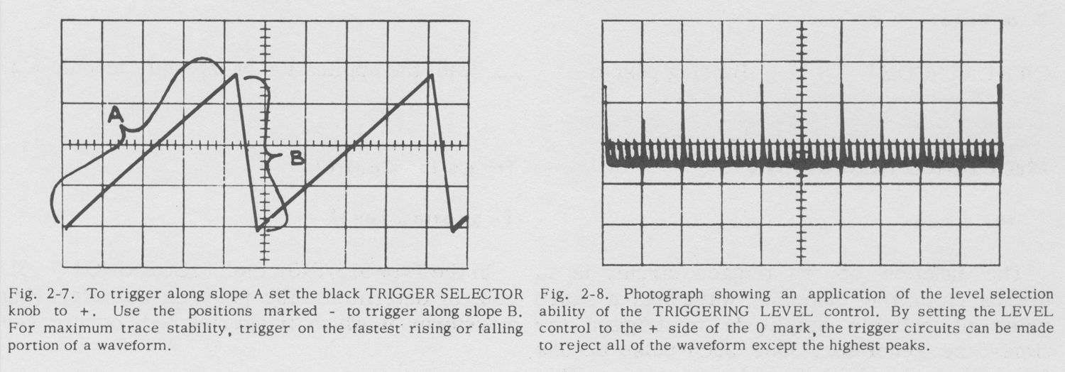
control determines the point on the triggering waveform at which triggering will occur. The TRIGGERING LEVEL control is not a trigger amplitude or gain control if you are accustomed to this type of circuit. Instead, it is an amplitude or voltage discriminator. If the waveform you are observing is centered on the screen and the TRIGGERING LEVEL control is set near 0 the sweep will start as the waveform passes through the center line on the screen. As the LEVEL control is turned clockwise, the triggering point will move above the center line on the screen, and, as it is turned counterclockwise the triggering point will move below the center line. If the LEVEL control is set for a voltage greater than that of the waveform being observed the sweep will stop. Thus, if the waveform is of low amplitude the LEVEL control should be set near 0 (or near the dc level with DC triggering). The LEVEL control is used only in the AC and DC positions of the TRIGGER SELECTOR switch.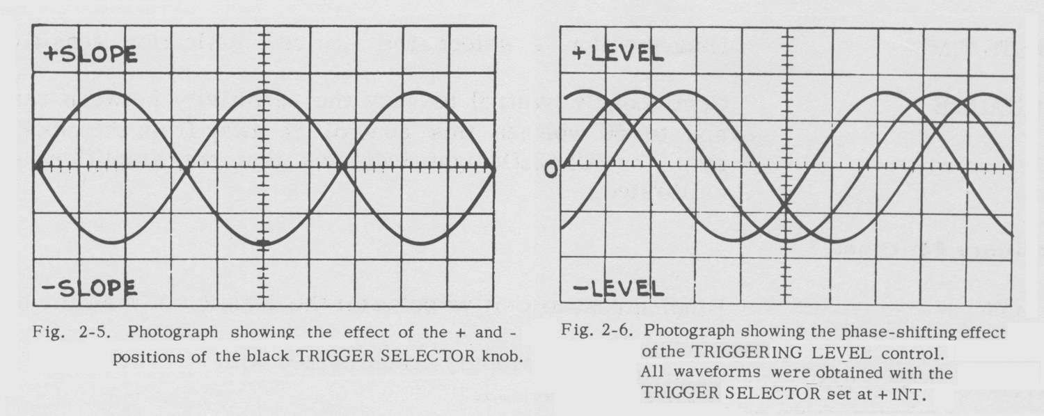
 Trigger Slope
The black TRIGGER SELECTOR knob selects the trigger source and determines whether the sweep will start as the waveform is going positive or negative. The + positions of this switch cause triggering to occur during the rising portion of the waveform. The – positions cause triggering to occur during the falling portion of the waveform. The trigger slope feature is not used in the H F SYNC mode.
Triggering Mode
The red TRIGGER SELECTOR knob selects the kind, or mode, of triggering used. The DC position will permit triggering on all signals from dc to about five megacycles. It is especially useful for signals below 60 cycles where the sensitivity of AC triggering begins to fall off.
In the AC position, the switch inserts a capacitor in the trigger circuits to make the trigger settings independent of the vertical position of the trace. This mode is slightly more sensitive than the DC mode.
The AUTO position arranges the circuits for an automatic synchronizing action rather than a strict triggering action. In this position the trigger-shaper multivibrator free-runs at
a repetition rate of about 50 cycles. The multivibrator will lock in and run synchronously with trigger signals from 60 cycles to about 2 megacycles. If the trigger signal is lost
the sweep will not stop but will continue at a reduced repetition rate without synchronization.
In the H F SYNC position the trigger-shaper circuits are bypassed and the triggering waveform is used to synchronize the time base circuits directly. The time-base generator must be free-running for this type of operation.
It free-runs at advanced settings of the STABILITY control. This mode of operation is primarily useful for signals in excess of two megacycles.»
§§§
Il testo prosegue nella terza parte.
Per consultare le altre schede dedicate a questo oscilloscopio scrivere: “515A” su Cerca.
Foto di Claudio Profumieri, elaborazioni, ricerche e testo a cura di Fabio Panfili.
Per ingrandire le immagini cliccare su di esse col tasto destro del mouse e scegliere tra le opzioni.