Oscilloscopio Tektronix Type 565 serial 689. Quarta parte.
Nell’inventario D del 1956 si trova al n° 3747 e risulta acquistato nell’agosto del 1964; vi si legge: “Silvestar ltd. Milano. Oscilloscopio Tektronix mod. 565 matr 689. Dest. Elettronica ₤ 1·678·600”. Insieme alla fotocamera che è al n° 3746, dove si legge: “Silvestar ltd. Milano. Macchina fotografica Tektronix mod. C-12 completa di Bezel-Tektronix. Dest. Elettronica. ₤ 557·700”.
Il testo continua dalla terza parte.
§§§
«SECTION 2
OPERATING INFORMATION
Introduction
This portion of the manual contains general information about the many features of the Type 565 and specific information about the use of each control. The information
is intended to help you gain full use of the potentialities of
the instrument.
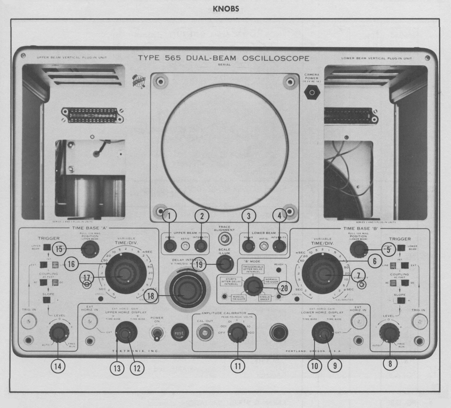
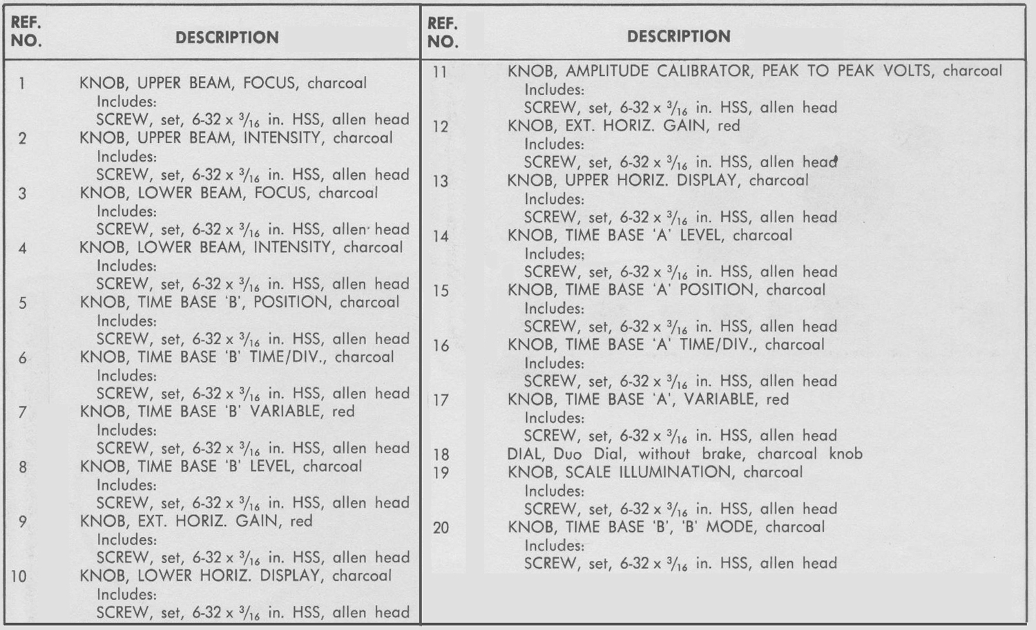
BRIEF DESCRIPTIONS OF CONTROL AND
SWITCH FUNCTIONS
NOTE
More complete descriptions of the controls and switches and how to use them is included in the latter portion of this section.
UPPER BEAM
These controls and switches are located on the left half of the front panel and affect the upper beam display.
UPPER HORIZ. DISPLAY
(Upper Horizontal Display) Provides selection between ‘A’ TIME BASE, ‘B’ TIME BASE, and EXT. [external] signal sources for horizontal deflection of the upper beam.
EXT. HORIZ. GAIN
(External Horizontal Gain) Functions only when the UPPER HORIZ. DISPLAY switch is in the EXT. position. Permits variation of the external horizontal input deflection sensitivity to a maximum of about 0.1 volt per division.
POSITION (Upper Beam)
(Not part of Time Base ‘A’) Used to move the display horizontally. This is a combination coarse and vernier control. About 55° vernier adjustment is available at any position of the control.
10X MAG. (Ten-Times Magnifier) Expands a one major division segment of the display to ten times normal width. The segment of the normal display which was positioned at the center of the crt will be displayed. When the 10X MAG. is used, the sweep rate is ten times faster than indicated by the TIME/DIV. switch. 10X MAG. has no effect when an external horizontal input is used.
FOCUS Adjust in conjunction with the ASTIG. control to obtain sharpest possible trace definition.
ASTIG. (Astigmatism) Adjusted so the FOCUS control can be set for equally sharp definition of both the horizontal and vertical portions of the display.
INTENSITY Allows variation of trace brightness.
LOWER BEAM
These controls and switches are located on the right half of
the front panel. They are identical in function to those provided for the upper beam display, but affect only the lower beam display.
TIME BASE ‘A’
These controls and switches are located on the left half of
the front panel and affect only Time-Base ‘A’.
TRIGGER
(UPPER BEAM) (LOWER BEAM) Functions only when the EXT.-INT.-LINE switch is in the INT. position. Selects between the Upper Beam and Lower Beam vertical channel signals as the source of triggering signal.
EXT.-INT.-LINE (External-Internal-Line) Provides a selection of triggering signal sources: external (EXT.) from TRIG. IN connector; internal lNT.) from either Upper or Lower Beam vertical channel, or a sample of the power line waveform (LINE)
COUPLING Allows acceptance or rejection of some
(AC-AC FAST- DC) characteristics of triggering signals. AC rejects dc and very low frequency ac signals. AC FAST rejects signals below about 1 kc. DC accepts all frequencies and dc.
SLOPE (+ -) Determines whether the sweep will trigger on the positive-going or negative-going portion of a signal.
LEVEL (AUTO.-FREE RUN) A three function control. Except at the extreme clockwise and counterclockwise positions, it operates as a triggering LEVEL control. LEVEL selects the amplitude point on the triggering signal at which the sweep will trigger. AUTO. (automatic) overrides the function of the COUPLING switch and LEVEL control and selects AC coupling and ‘0’ level. In the absence of a triggering signal, a reference trace is displayed on the crt (about 50 sweeps per second, maximum). The FREE RUN position provides recurrent sweeps at a rate depending upon the TIME/DIV. switch setting (about 12,000 sweeps per second at one microsecond per division).
STABILITY A screwdriver adjustment which sets the time-base generator susceptibility to pulses from the trigger circuits.
TIME/DIV. (Time Per Division) Selects the rate at which the spot moves across the crt.
VARIABLE An uncalibrated control which provides sweep rates other than those included on the TIME/DIV. switch. Rates to less than 0.4 of that indicated by the TIME/DIV. switch can be obtained.
DELAY INTERVAL (‘A’ Time Per Division Multiplied by a figure between one and ten). Used with ‘A’ TIME/DIV. switch to determine the delay interval between the start of ‘A’ sweep and the delayed trigger pulse. This pulse is fed to a rear-panel output connector and to the ‘B’ MODE switch. With the proper setting of the ‘B’ MODE switch, this pulse can either; (1) start ‘B’ sweep (STARTS AFTER DELAY INTERVAL) or (2) make ‘B’ sweep susceptible to trigger pulses (TRIGGERABLE AFTER DELAY INTERVAL).
TIME BASE ‘B’
These controls and switches are located on the right half
of the front panel and are identical to those for Time-Base
‘A’ with the addition of the following:
‘B’ MODE Selects the type of operation that Time Base ‘B’ will perform. In the NORMAL TRIGGER position, the operation is identical to that of Time Base ‘A’. TRIGGERABLE AFTER DELAY INTERVAL and STARTS AFTER DELAY INTERVAL are explained previously under “DELAY INTERVAL”.
 MANUAL TRIGGER and SINGLE SWEEP
function as follows:
MANUAL TRIGGER Overrides all TIME BASE ‘B’ TRIGGER controls. The spot will sweep across the crt once each time the MANUAL TRIGGER button is pushed.
SINGLE SWEEP Permits Time Base ‘B’ to move the spot across the crt once each time the SINGLE SWEEP button is pushed. Pushing the button does not start the sweep; it permits the trigger circuit to do so.
AMPLITUDE CALIBRATOR
PEAK-TO-PEAK VOLTS Selects output voltage delivered to the CAL. OUT connector from the available decade steps, .001 volt to 100 volts. It also permits turning off the Amplitude Calibrator.
OTHER CONTROLS
TRACE ALIGNMENT Used to rotate the crt display to coincide with the graticule markings.
SCALE ILLUM (Scale Illumination) Adjusts the brightness of the graticule markings.
POWER ON Ac line switch.
FIRST-TIME OPERATION
The following information is intended to help you prepare your Type 565 Oscilloscope for first-time use. It is also suggested that a quick-check, similar to these steps, be performed each day before beginning measurements.
Whenever plug-in units are exchanged, steps 10 and 11
must be checked.
1. Install any general-purpose amplifier plug-in units (e.g. 3A1, 3A2, 2A60, 2A63, 3A75, 3A72, 3A74, etc.).
2. Set Upper and Lower Beam display controls and switches as follows:
INTENSITY counterclockwise
POSITION (horiz.) centered
10X MAG. off (pushed in)
UPPER HORIZ. DISPLAY ‘A’ TIME BASE
LOWER HORIZ. DISPLAY ‘B‘ TIME BASE
3. Set the applicable controls and switches on both vertical
plug-in units as follows:
VOLTS/DIV. 5
VARIABLE CALIBRATED
AC-DC-GND. AC
POSITION (vert.) centered
4. Set TIME BASE ‘A’ and TIME BASE ‘B’ controls and
switches as follows:
TIME/DIV. .2 mSEC
VARIABLE CALIBRATED
LlNE—lNT.—EXT. LINE
LEVEL AUTO.
STABILITY clockwise (screwdriver adjustment)
5. Set the remaining controls and switches as follows:
‘B’ MODE NORMAL TRIGGER
PEAK-TO-PEAK VOLTS 10
NOTE
Controls not mentioned may be left in any position.
6. Connect the power cord to the proper voltage source
and turn on instrument power.
7. Allow several minutes for the instrument to warm-up.
Then, slowly advance the INTENSITY controls to obtain
traces of moderate brightness. It may be necessary to
readjust the vertical POSITION controls.
8.Slowly turn the Time Base ‘A’ STABILITY control
counter-clockwise. The upper beam trace should dim and then
disappear. Set the STABILITY control in the middle of the
“dim” range. Adjust the Time Base ‘B’ STABILITY control
in the same manner.
NOTE
This setting of the STABILITY control is correct for most applications. However, when the triggering signal frequency is above approximately one megacycle, it may be necessary to make a slight readjustment to obtain a completely stable display.
9. Connect the CAL. OUT signal to the INPUT connector of both vertical plug-in units. Set the LINE—INT.— EXT. switch in both time-base blocks to INT. Adjust the
INTENSITY controls so the vertical lines in the square wave display are just visible.
10. Adjust the FOCUS controls so the vertical and horizontal portions of each display are equally focused. Then adjust the ASTIG. controls for best focus in the horizontal and vertical portions of each display. Repeat the
adjustments, if necessary, until no further improvement can be made.
NOTE
It may be necessary to touch-up the FOCUS control adjustment whenever a major change is made in the INTENSITY control setting. In some applications, such as those involving low repetition rate signals displayed at fast sweep rates, a very dim display will be obtained. Since better display focus can be obtained when the INTENSITY
control is set below maximum, you may wish to use a moderate INTENSITY control setting and a viewing hood. The viewing hood will block external light and make dim displays useable.
11. Use a screw driver to set the gain adjustment on the front panel of the plug-in units so each of the square wave displays is exactly 2 major divisions in amplitude.
If you require additional information about this adjustment, see the manual for your particular plug-in unit.
12. Remove the signal input leads. Turn both trigger LEVEL controls fully clockwise. The traces should be parallel to the horizontal graticule lines. If not, adjust the TRACE ALIGNMENT control to remove any tilt. NOTE
The TRACE ALIGNMENT control is a screw-driver-
adjustment located on the front panel just below the crt. This control permits the operator to easily offset any trace tilt introduced by the earth’s magnetic field.
When the preceding steps have been completed, the
Type 565 Oscilloscope is ready for use.
NOTE
It is important that steps 10 and 11 be rechecked each time plug-in units are exchanged in the Type 565.
USING THE TYPE 565
Signal Input Connections
Signals to be displayed on the oscilloscope are connected to the input connectors of the vertical plug-in units.
The signals within the plug-in unit are then changed to the
proper amplitude and used to produce vertical deflection
of the electron beams. It is frequently possible to make the
input connections with unshielded test leads. This is
particularly true when you are observing a high-level, low-frequency signal from a low impedance source. When test
leads are used, place a ground connection between the
oscilloscope chassis and the output “common” terminal of
the signal source.
In many applications, unshielded leads are unsatisfactory
for making input connections due to the noise pickup
resulting from stray magnetic fields. In such cases, shielded
cables should be used. The ground conductors of the cable
must be connected to the chassis of the oscilloscope and
the output “common” terminal of the signal source.
In high-frequency applications, it is usually necessary to
terminate the signal source and connecting cable in their
characteristic impedance. Unterminated connections may
result in reflections in the cables and cause distortion of
the displayed waveforms.
In general, a termination resistor connected at the input
connector of the plug-in unit will produce satisfactory
results. In some cases, however, it may be necessary to
terminate cables at both ends. The need for proper terminations increases as frequency increases.
In analyzing the displayed waveforms, you must consider
the loading effect of the oscilloscope on the signal source.
The input resistance of the vertical plug-in unit is usually
adequate to limit low-frequency loading to a negligible
value. At high frequencies, however, the input capacitance
of the plug-in unit and the distributed capacitance of input
cables become important. Capacitive loading at high frequencies may be sufficient to adversely affect both the
displayed waveform and operation of the signal source.
Both capacitive and resistive loading can usually be limited
to negligible values through use of attenuating signal probes.
Signal Probes
In addition to providing isolation of the oscilloscope from
the signal source, an attenuator probe decreases the amplitude of the displayed waveform by the attenuation factor of the probe. Thus, a probe allows you to increase the
vertical-deflection factor so high-amplitude signals, beyond
the normal limits of the oscilloscope and plug-in combination, may be observed. Signal amplitudes, however, must be limited to the maximum allowable value for the probe used.
Before using a probe, you must check (and adjust it necessary) the probe compensation to be certain the waveform will be correctly displayed. To do this, connect the probe tip to the CAL. OUT connector and obtain a display of about 2 major divisions. Then, if necessary, adjust the probe compensation.
Horizontal Sweeps
Horizontal sweep signals for the Type 565 Oscilloscope
are usually produced by the two time-base generators.
Either beam can be deflected by either time base. Or, if
desired, both beams may be swept simultaneously by the
same time base. The selection of time base is made with
the UPPER and LOWER HORIZ. DISPLAY switches.
The sweep rates of the two beams are determined by
the settings of the appropriate TIME/DIV. switch. The sweep characteristics of the two time bases are identical. Each time base provides 21 calibrated sweep rates ranging from 1 microsecond to 5 seconds per division. Uncalibrated
VARIABLE TIME/DIV. controls permit continuously variable sweep rates between I microsecond and approximately 12 seconds per division.
Sweep Magnifiers
Signals displayed with either of the two beams can be expanded ten times horizontally by using the appropriate 10X MAG. switch. Magnification is obtained when the 10X
MAG. switch is pulled outward. This switch has no effect
when the horizontal deflection is produced by external
signals. The magnifiers increase the observed sweep rates
by 10 times the TIME/DIV. control settings. The true sweep
time per division is found by multiplying the settings of the
TIME/DIV. controls by 0.1.
The 1-division portion at the horizontal center of the
graticule of an unmagnified display is expanded and
remains centered in the full 10-division width of the graticule when the magnifier is turned on. Any other I-division portion of the original unmagnified display can then be observed in magnified form by using the HORIZONTAL POSITION control to position that portion on the crt.
Sweep Triggering
In most cases, it is desirable for a repetitive signal to produce a stationary display on the crt so that the
characteristics of the waveform can be examined in detail. As a necessary condition for this type of display, the start of
each sweep must bear a definite, fixed-time relationship to
the events in the input signal. In the Type 565 Oscilloscope,
this is accomplished by using the displayed signal or another related signal to start (trigger) each single or
repetitive sweep.
The four TRIGGER slide switches and the LEVEL control
provide complete control over the means of triggering the
sweep. Triggering controls for Time Base ‘A’ and Time Base ‘B’ are identical. Thus, the following information applies to both.
Selecting the Triggering Signal Source
The triggering signal for either time base can be obtained
from any one of four sources; the Upper Beam vertical
amplifier, the Lower Beam vertical amplifier, the power
line (via the power transformer), or from an external source.
It is usually convenient to trigger the sweeps internally
from either the upper or lower beam vertical signals. This
is done by placing the EXT. INT. LINE switch to the INT.
position and then setting the UPPER BEAM-LOWER BEAM switch to the appropriate position.
If the displayed signal frequency is related to the power
line frequency, the LINE source can be used. This source is
particularly useful when the displayed signal will not allow
stable internal triggering.
External (EXT.) triggering is often used when signal tracing
in amplifiers, phase shift networks, and wave-shaping circuits. The signal from a single point in the circuit can be
used to trigger the sweep. It is then possible to observe the
shaping and amplification of the signal at various points in the circuit without resetting the triggering controls.
Selecting The Triggering Slope
The sweeps can be triggered during either the rising or
tolling portion of the triggering signal. When the display
consists at several cycles of the input signal, either setting
of the SLOPE switch may be used. However, it you wish to display less than one full cycle at the input signal, the
SLOPE switch will permit you to start the sweep on the
desired slope; either rising (+ slope) or falling (- slope).
Trigger Input Coupling
The trigger COUPLING switch permits you to accept or
reject certain properties of triggering signals. Three means of coupling are provided; DC, AC, and AC FAST. of all frequencies, and dc levels.
AC coupling rejects the dc component of trigger signals
and attenuates ac signals below about 20 cycles.
AC FAST coupling rejects the dc component of trigger signals and ac signals below about 1000 cycles.
In general, the AC position of the COUPLING switch
should be used. It will be necessary to use DC coupling
for very low frequency triggering signals. AC FAST coupling should be used when triggering internally from multi-trace plug-in units operated in the alternate mode (unless the “Trigger From Channel One Only” feature at the plug-in is being used). Also, it line frequency hum is mixed with a desired high frequency triggering signal, best results may be obtained using AC FAST coupling.
Use of the LEVEL Control
The LEVEL control has two switch positions (AUTO. and FREE RUN) and a variable mid-region (LEVEL). The function of each is as follows:
Level — This function of the control operates except at
the clockwise and counterclockwise extremes. The LEVEL
control determines the instantaneous voltage level on the
triggering signal at which the sweep is triggered. (This
instantaneous voltage level can include a dc component if
the COUPLING switch is set to DC.). With the SLOPE switch in the + position, adjustment of the LEVEL control makes it possible to trigger the sweep consistently at virtually any point on the positive slope at the triggering signal. Likewise, with the SLOPE switch in the — position, adjustment of the LEVEL control makes it possible to trigger the sweep consistently at virtually any point on the negative slope of the triggering signal.
Auto. — Automatic triggering is frequently used for ease
of operation. It can be used to observe a large variety of
signals with simplicity, requiring no setting of the TRIGGER controls. Automatic triggering is useful for obtaining stable displays at signals in the range from approximately 60 cycles to one megacycle. In AUTO. operation, the trigger SLOPE and source can be selected, but the triggering level and trigger coupling cannot. Each sweep is triggered at the average voltage level of the ac-coupled triggering signal.
In the absence of a triggering signal, the sweep continues
to run to provide a convenient reference trace on the crt.
The maximum repetition rate of the reference trace sweeps
is about 50 sweeps per second and therefore, the trace
may not be visible when the fastest sweep rates are used.
Free Run — FREE RUN operation produces repetitive
sweeps, independent of any triggering signal. These sweeps
will provide a reference trace, as does AUTO., but it will
have normal intensity at any sweep rate. This method of
operation is useful in applications where the device under
test requires a trigger or input signal. The appropriate rear
panel + GATE OUT or HORIZ. SIG. OUT signal may be
fed to the device to cause its operation. The resulting
signals displayed on the crt will be synchronized with the
sweep.
Using the ‘B’ MODE Switch
The ‘B’ MODE switch permits operating Time Base ‘B’ in
any of five different ways:
1.Normal Trigger
2.Single Sweep
3.Manual Trigger
4.Starts After Delay Interval
5.Triggerable After Delay Interval
The following paragraphs describe typical procedures used
in operating Time Base ‘B’ in each mode.
Normal Trigger
When the ‘B’ MODE switch is in the NORMAL TRIGGER
position, the operation of Time Base ‘B’ is independent of, but identical to that of Time Base ‘A’.
Single Sweep
Single Sweep is often used when photographing non-repetitive waveforms and in other applications where the
signal varies in amplitude, shape, or time interval. A
continuous display of such signals would appear as a jumbled mixture of many different waveforms and would yield little or no useful information.
The Type 565 Oscilloscope permits you to obtain a single-sweep presentation and eliminate all subsequent sweeps so information is clearly recorded without the confusion resulting from multiple traces.
The single sweep function of Time Base ‘B’ is selected by
placing the ‘B’ MODE switch in the SINGLE SWEEP position.
As the change is made from NORMAL TRIGGER mode to SINGLE SWEEP mode, the Time Base remains triggerable. If there is sufficient delay before triggering, the READY lamp will light to show that the time base is “ready” to be triggered. When the time base has been triggered and one sweep is completed, the time base becomes in-operative and the READY lamp will be extinguished. This shows that the single sweep has been initiated.
The time base can be “reset” to the triggerable condition
by pressing the RESET button, located to the right of
the ‘B’ MODE switch. The time base will then be “ready” to produce another single sweep when a suitable triggering
signal is applied.
Manual Trigger
The Manual Trigger mode operates similarly to Single Sweep. The only difference is that Time Base ‘B’ always
begins the sweep when the MANUAL TRIGGER button is
pressed.
STARTS AFTER DELAY INTERVAL
Introduction
The following information is given in the form of
demonstration procedures. They are intended to show some of the various measurements and other operations that can be performed by using the delayed ‘B’ sweep; the accuracy of those measurements; and the operating procedures
involved.
Set the controls and switches on the instrument as listed
in following paragraphs. Set the Upper Beam horizontal
POSITION so the trace begins precisely at the left-hand
edge of the graticule. Notice the position of the intensified
segment in the Upper Beam trace.
Now set ‘A’ TIME/DIV. to .2 SEC and ‘B’ TIME/DIV. to
20 mSEC. The intensified segment should be at the same
position as with the previous sweep rates.
Turn the Lower Beam INTENSITY control for a visible trace. Notice that the Lower Beam trace and the intensified
segment in the Upper Beam trace begin at the same time. This display shows that Time Base ‘B’ produces one sweep during each ‘A’ sweep. The Time Base ‘B’ TRIGGER switches and LEVEL control have no effect on the operation.
The Time Base ‘A’ sweep rate is .2 second per division and
the intensified segment begins 5 major divisions after the
beginning of the Upper Beam trace. Hence, the Lower Beam Time Base ‘B‘ sweep starts one second after the
beginning of the Upper Beam Time Base ‘A’ sweep (0.2
second per division times 5 divisions equals 1 second).
The number of major divisions between the beginning of
the Upper Beam sweep and the beginning of the intensified
segment is established by the setting of the DELAY INTERVAL control. Therefore, with any dial setting greater than about 0.50, the time difference between the beginning of the ‘A’ and ‘B‘ sweeps is the product of the Time Base ‘A’ sweep rate and the DELAY INTERVAL dial setting.
The following demonstration procedures are intended to
show five of the most commonly used applications of the
delayed sweep feature. The applications include time
measurements which are more accurate than those obtained
directly from the crt display, and other operations that can only be performed on oscilloscopes having a delayed sweep
feature. Set the Type 565 controls and switches as follows:*
TRIGGER (Time Base ‘A’) UPPER BEAM
EXT.-INT.-LINE INT.
COUPLING AC
SLOPE +
LEVEL AUTO.
‘A’ TIME/DIV. 1 mSEC
‘B’ TIME/DIV. .1 mSEC
VARIABLE (‘A’ & ‘B’) CALIBRATED
‘B’ MODE STARTS AFTER DELAY
INTERVAL
DELAY INTERVAL 5.00
PEAK-TO-PEAK VOLTS
(Amplitude Calibrator) 10
UPPER HORIZ. DISPLAY ‘A’ TIME BASE
LOWER HORIZ. DISPLAY ‘B‘ TIME BASE
10X MAG. (both) off (pushed in)
horiz. POSITION (both) centered
Upper Beam INTENSITY so both intensity levels in the Upper Beam trace are easily seen
Lower Beam INTENSITY counterclockwise
Set the controls and switches of both vertical plug-in units*
as follows:
VOLTS/DIV. 5
VARIABLE CALIBRATED
AC – DC – GND DC
POSITION centered
*Controls not mentioned may be left in any position. »
§§§
Il testo prosegue nella quinta parte.
Per consultare le altre schede dedicate a questo oscilloscopio esposto al Museo MITI (su proposta di fabio Panfili) scrivere “565” su Cerca.
Elaborazioni e testo a cura di Fabio Panfili.
Per ingrandire le immagini cliccare su di esse col tasto destro del mouse e scegliere tra le opzioni.