Oscilloscopio Tektronix Type 565. Sesta parte.
Nell’inventario D del 1956 si trova al n° 3747 e risulta acquistato nell’agosto del 1964; vi si legge: “Silvestar ltd. Milano. Oscilloscopio Tektronix mod. 565 matr 689. Dest. Elettronica ₤ 1·678·600”. Insieme alla fotocamera che è al n° 3746, dove si legge: “Silvestar ltd. Milano. Macchina fotografica Tektronix mod. C-12 completa di Bezel-Tektronix. Dest. Elettronica. ₤ 557·700”.
Il testo continua dalla quinta parte.
§§§
«SECTION 3
CIRCUIT DESCRIPTION
General
This portion of the Instruction Manual presents a detailed
discussion of the Type 565 circuitry operation. This discussion refers to various block diagrams inserted in the text, and to the circuit diagrams in the back of this manual.
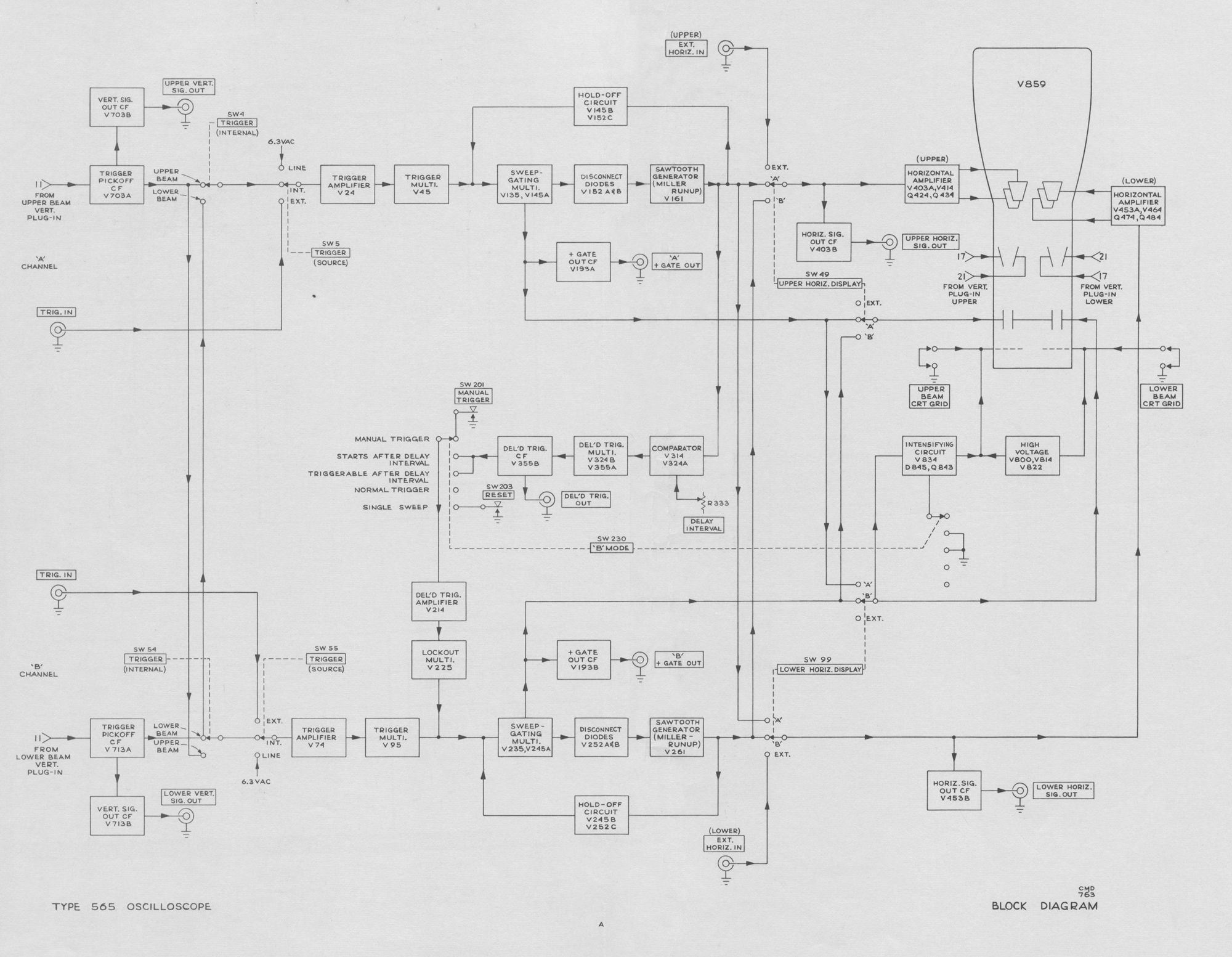
BLOCK DIAGRAM
A functional block diagram at the Type 565 Oscilloscope is shown in Fig. 3-1. The relationship of the circuits in each
block to those in other portions of the instrument is discussedin the detailed description of that circuit.

TIME BASE TRIGGER
General
Time Base ‘A’ Trigger and Time Base ‘B’ Trigger circuits are identical except for component reference numbers on
the schematics. The following circuit description pertains
to both circuits, but reference numbers for Time Base ‘A’
Trigger are used.
For best triggering stability, the Time Base Generator
requires a trigger pulse that is representative of the selected
triggering signal frequency, but otherwise consistent in
amplitude and wave-shape. Available triggering signals often vary in amplitude, waveshape, and frequency, and thus cannot be used directly to trigger the time base. The Trigger circuit is essentially a waveshaping circuit that converts a sample of the input signal into a pulse having a reasonably constant risetime and amplitude. Hence, frequency is the only variable characteristic remaining in the output trigger pulse.
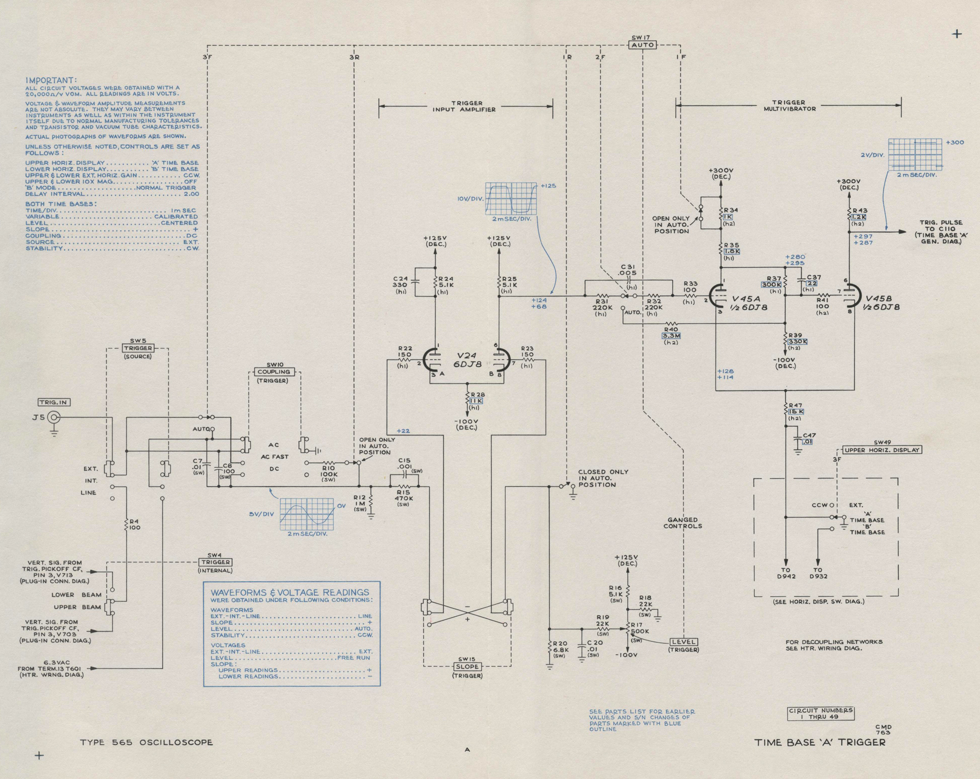
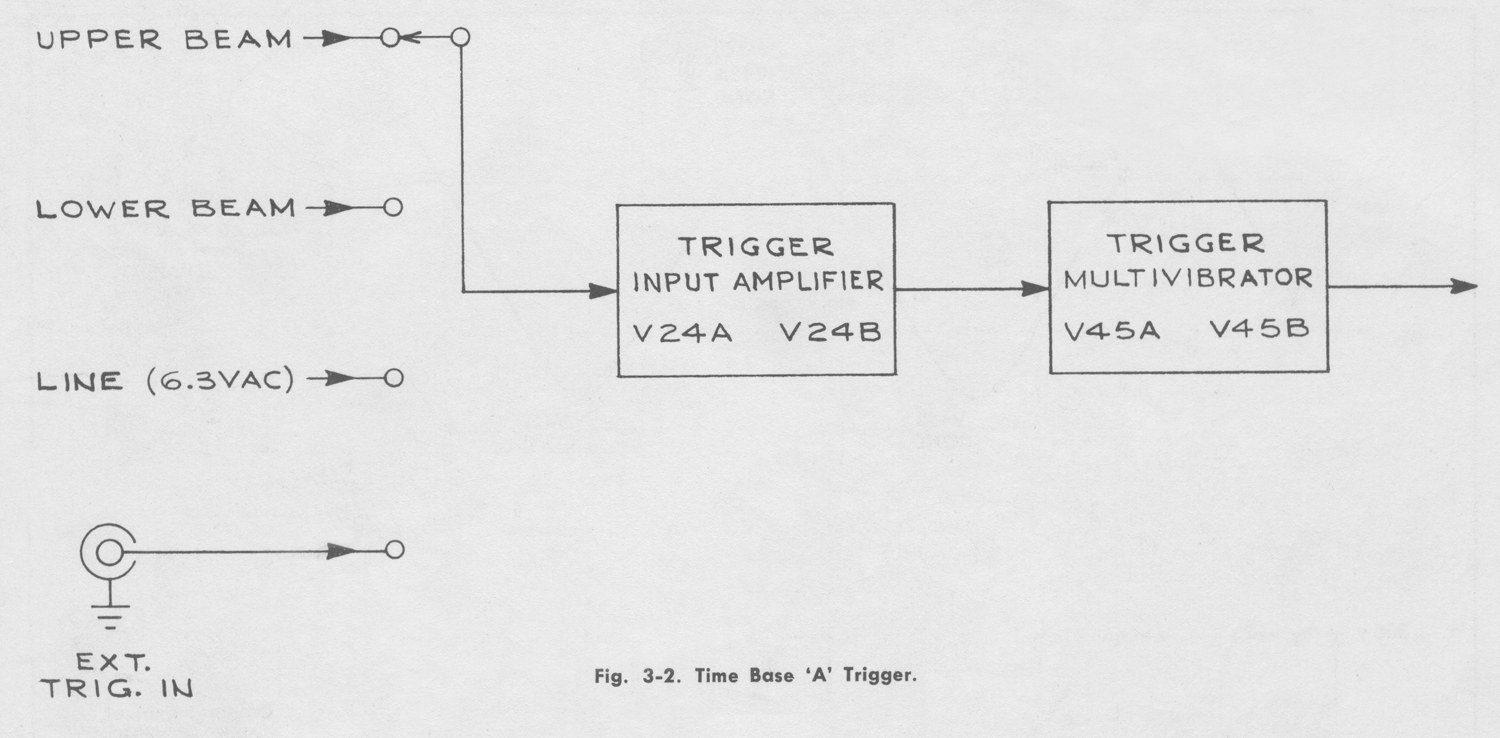
The block diagram, Fig. 3-2, shows the two basic elements
of the trigger circuit. The Trigger Input Amplifier amplifies
(and when desired, inverts) the incoming triggering signal and applies it to the input grid of the Trigger Multivibrator. The Trigger Multivibrator is essentially a switch that is either on or off, depending on the instantaneous voltage level at its input. Its square wave output is applied to the Time Base Generator where it is differentiated to form positive and negative pulses. The negative pulses trigger the Time Base Generator while the positive pulses are clipped and not used.
 For the following description, refer to the Time Base ‘A’
Trigger schematic in the back of this manual.
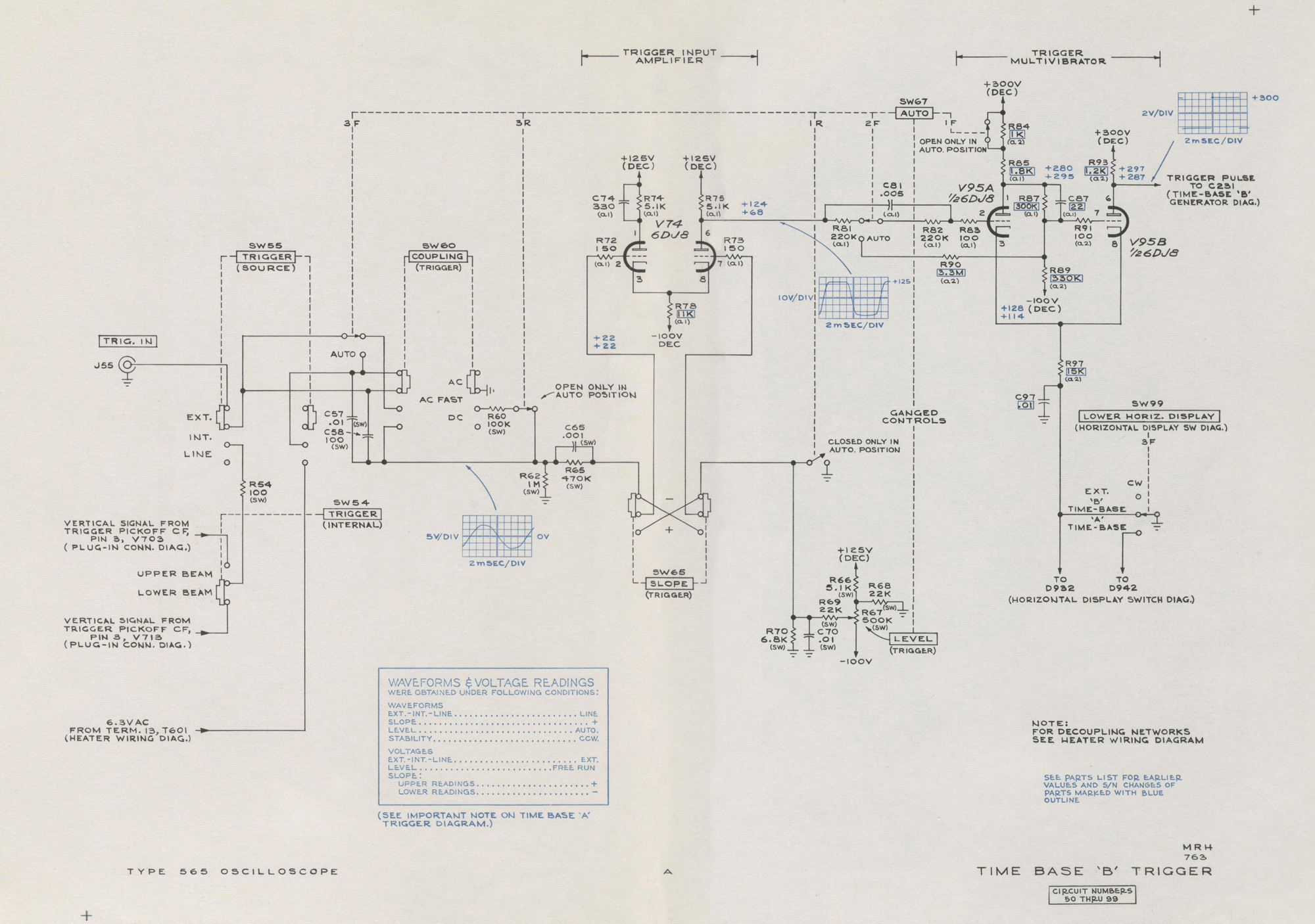
Trigger Input Amplifier
The TRIGGER source switches are used to select the
appropriate trigger signal from one of four sources: upper beam vertical plug-in unit (UPPER BEAM), lower beam vertical plug-in unit (LOWER BEAM), TRIG. IN connector (EXT.), or line-frequency signal from the power transformer (LINE). Theselected signal is then applied to the COUPLING switch. (Information about the automatic mode, AUTO., of trigger operation is given later in this circuit description).
The COUPLING switch permits the operator to accept or
reject certain characteristics of the triggering signal. In the DC position, the coupling capacitors are shorted, coupling
both dc and ac signals to the Trigger Input Amplifier. In
the AC position, C7 and C8 in parallel are placed in the
signal path. An RC circuit consisting of C7-C8 and R12 is thus formed which blocks dc and attenuates ac signals below about 20 cycles. In the AC FAST position, C8 alone is placed in the signal path and R12 is placed in parallel with R10. This RC network blocks dc and rejects ac signals below 1000 cycles. The TRIGGER source and COUPLING switches are wired so the AC FAST function is bypassed when the LINE source is used.
The signal from the COUPLING switch is applied to the
SLOPE switch through R15-C15. (R15 and C15 prevent high amplitude positive signals from drawing excessive grid
current from V24.) The SLOPE switch determines whether or not the triggering signal will be inverted by the Trigger Input Amplifier. When the SLOPE switch is set to —, the signal is applied to the grid of V24A and will not be inverted. For example, a positive-going signal at the grid of V24A will cause a positive-going change in the common cathode circuit. The fixed voltage at the grid of V24B and the positive going change at its cathode reduce the current through V24B. This results in a positive-going change in plate voltage; hence, no inversion.
If the SLOPE switch is in the + position, the signal is applied to the grid of V24B. In this case, V24B inverts the
signal in the manner characteristic of a single stage, plate-loaded amplifier.
The SLOPE switch also serves another function, it applies
a dc voltage from the LEVEL control to whichever grid of V24 is not connected to the COUPLING switch. (The need for this dc voltage is explained in the Trigger Multivibrator portion of this circuit description. At this point, however, the important consideration is the effect the dc voltage has on the amplified trigger signal at the plate of V24B.)*
The voltage at the junction of R19 and R20 can be varied
between about +15 and -15 volts by adjusting the LEVEL
control. This voltage controls the average voltage at the plate of V24B and the triggering signal either adds to or
subtracts from that average. Thus, in addition to being an
amplifier, the Trigger Input Amplifier is also a voltage
comparator. (V24 is a voltage comparator rather than a
difference amplifier since R24 and C24 balances the gain of V24A to that of V24B.) This composite signal is applied to the input grid of the Trigger Multivibrator.
The Trigger Multivibrator is disabled unless R47 is grounded.
If the UPPER HORIZ. DISPLAY switch, LOWER HORIZ.
DISPLAY switch, or ‘B’ MODE switch is set for a function in which the operation of Time Base ‘A’ is required, then
R47 will be grounded.
Trigger Multivibrator
The Trigger Multivibrator, V45, is a typical bistable Schmitt
circuit. When the voltage at the grid of V45A is above a
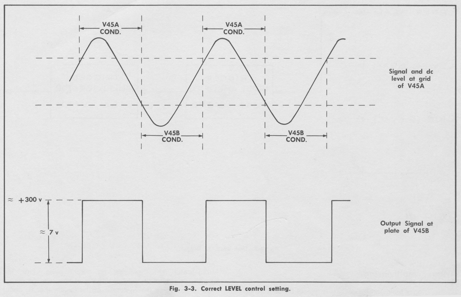
certain level, V45A conducts and V45B is cut off. In this state, the output voltage at the plate of V45B is +300 volts. When the voltage at the grid of V45A is below a certain level, V45B conducts and V45A is cutoff. The output voltage at the plate of V45B is then about +293 volts. The transition from one state to the other occurs very rapidly, regardless of how slowly the input voltage passes the trip-level. Thus, the output of the Trigger Multivibrator is a square pulse of about 7 volts amplitude. The following example illustrates the sequence of events.
When a negative-going voltage change reaches about +111 volts at the input grid, the plate of V45A rises and carries the grid of V45B with it. V45B is driven into conduction (see Fig. 3-3). Since the cathode resistor R47 is common to both tubes, the conduction of V45B tends to raise the
cathode voltage of V45A. This further reduces the current
flow through V45A and compounds the original action of the input signal. V45A and V45B rapidly change conduction states; V45A cuts off and V45B conducts. The voltage at the plate of V45B drops sharply. This voltage step is applied to a differentiating network in the Time Base Generator and becomes the negative-going trigger pulse required to start the time base action.
As the input signal continues into the positive-going portion of a cycle, the grid of V45A rises beyond +111 volts to about +113 volts before the Trigger Multivibrator resets to its previous state. This approximate 2 volt difference in switching levels is the hysteresis range of the circuit.
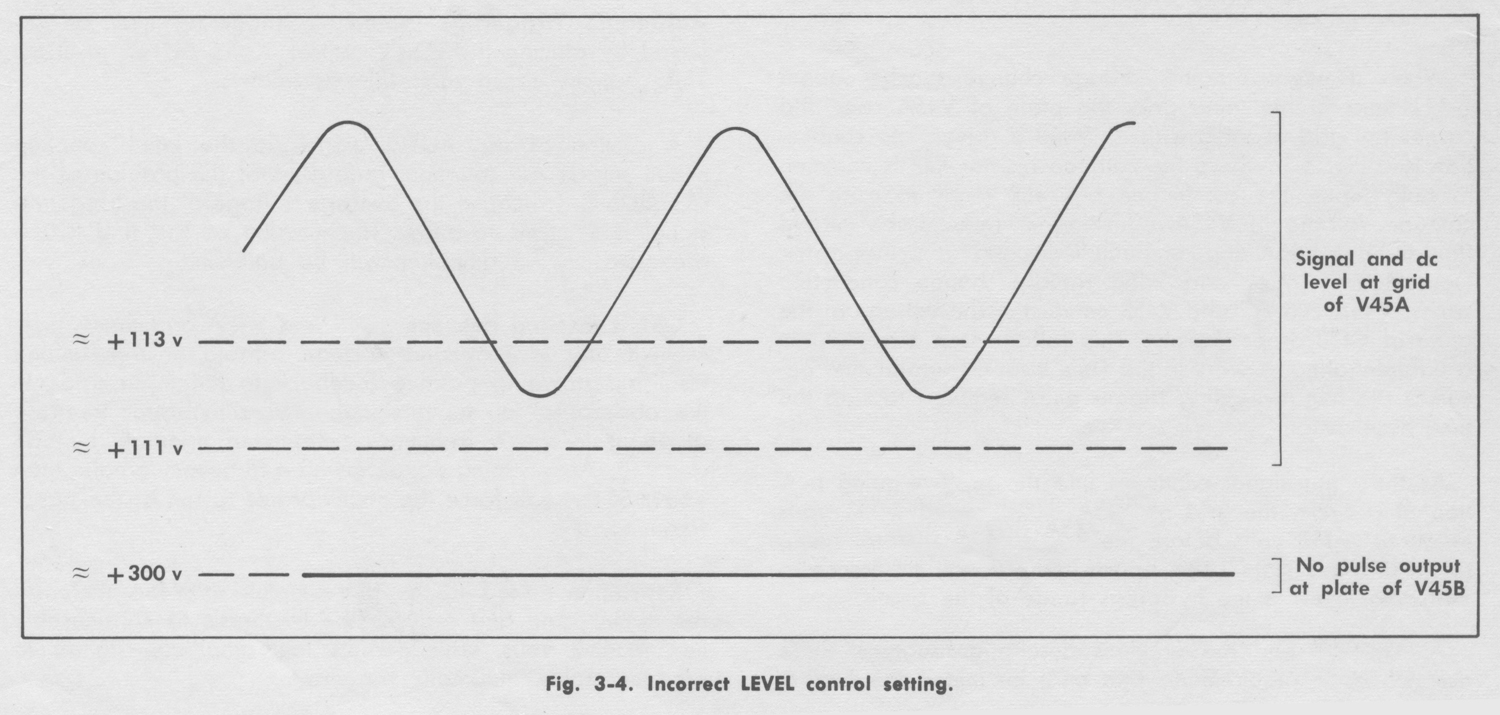
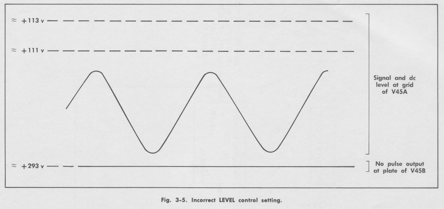
As Fig. 3-3 and the previous description suggest, there are two basic requirements that must be met if the Trigger Multivibrator is to generate an output pulse. First, the
amplified signal at the grid of V45A must have enough
amplitude to overcome the hysteresis of the circuit; that is, about 2 volts peak to peak, or more. Second, the signal must be superimposed on a dc voltage that will permit it to cross the upper and lower hysteresis limits of the circuit; that is, about +111 volts and +113 volts. This second requirement is met through the use of the LEVEL control mentioned previously. Figures 3-4 and 3-5 illustrate the consequence of improper LEVEL control adjustment. In both cases, the signal amplitude is adequate to produce triggering, but the dc level of the signal is incorrect.
Automatic Triggering—Automatic triggering may be
selected by placing the LEVEL control in the AUTO. position.
This changes circuit operation as follows:
A section of the AUTO. switch in the input coupling circuit selects AC coupling, regardless of the position of the COUPLING switch, so the average voltage of the triggering signal is reduced to zero. The junction of R19 and R20 is
grounded so the amplifier will be balanced. C31 is inserted between V24B and V45A and the Trigger Multivibrator is converted into an astable or free-running form by providing positive feedback to the input grid. In the absence of an input signal, the multivibrator free-runs at about 50 cps; a frequency determined primarily by C31 and R40. An incoming signal having a frequency greater than about 50 cps will force the multivibrator to run at the signal
frequency.
Resistance added in the plate circuit of V45A increases the circuit gain and reduces the hysteresis to considerably less than 2 volts. This permits low amplitude signals to produce stable automatic triggering.
TIME BASE GENERATORS
The following description pertains to both time bases, but circuit reference numbers for Time Base ‘A’ are used.
The additional circuitry in Time Base ‘B’ is described in
a later portion of this section under the title “Time Base
‘B’ Lockout”.
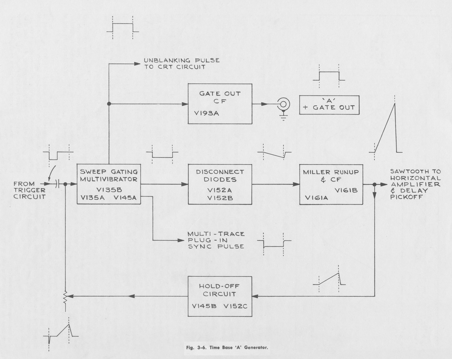
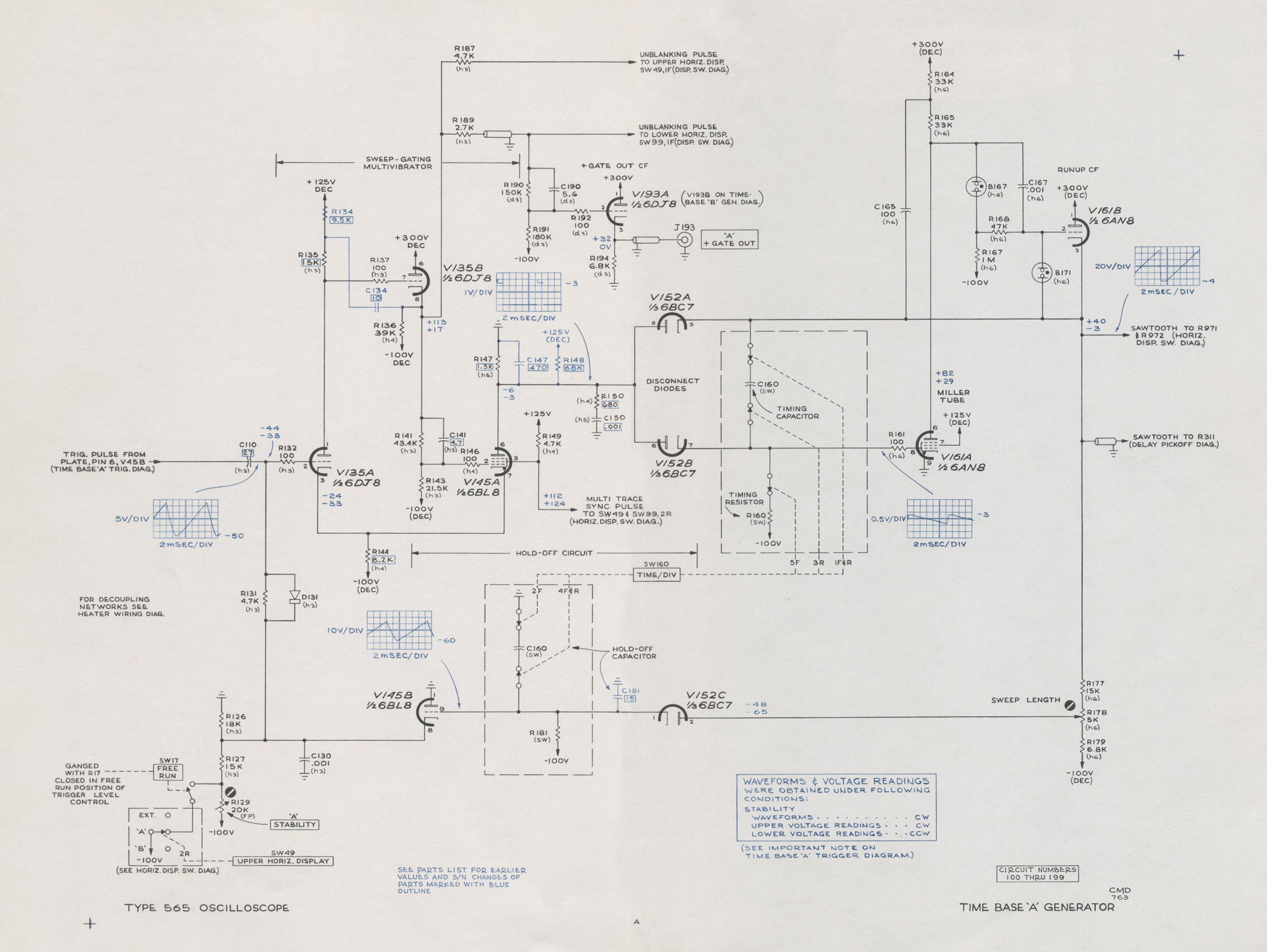
The Time Base Generator produces four output signals (see
Fig. 3-6):
1. a positive-going sawtooth which can be coupled to either or both horizontal amplifiers by the appropriate setting of the Horizontal Display switches. The sawtooth output is also permanently connected to the Delay Pickoff circuit (Time-Base ‘A’ only)
2. a positive-going unblanking pulse having the same duration as the sawtooth rise. Coupled to the Crt Circuit by
the Horizontal Display switches to unblank the beam(s)
being deflected by Time Base ‘A’.
3. a positive-going pulse (+ GATE OUT) having the same duration as the sawtooth rise. Coupled to a rear panel connector for external use.
4. a negative-going multi-trace sync pulse having the same
duration as the sawtooth rise. Coupled to the appropriate Vertical Plug-In Unit(s) by the Horizontal Display
switches. The trailing edge of the pulse causes multi-trace
plug-in units, operating in the alternate mode, to switch channels.
In most applications, each cycle of events is started by a trigger pulse from the Time Base Trigger circuit. However it is also possible to either disable the generator or to make it free run; that is—the end of one cycle will cause the next cycle to begin. The desired mode of operation will be
obtained through the appropriate setting of the STABILITY
and LEVEL (FREE RUN position) controls. (See Section 2.)
The block diagram, Fig. 3-6, shows the basic elements of
the Time Base Generator. The Sweep Gating Multivibrator is an electronic switch which turns the Disconnect Diodes on and off. When the Disconnect Diodes are back-biased, the Miller Runup begins to produce a sawtooth signal. A sample of the sawtooth is fed back to the Sweep Gating Multivibrator through the Holdoff Circuit. When the sawtooth sample reaches a predetermined amplitude, the Sweep Gating Multivibrator resets, switching the Disconnect Diodes.
The Miller Runup then resets, forming the retrace or falling
portion of the sawtooth. A sample of the sawtooth retrace is fed back to the Sweep Gating Multivibrator, but is delayed by the Holdoff Circuit. This delay prevents the generator from beginning the next sawtooth until the circuits have stabilized.
In the following detailed circuit description, refer to the
Time Base ‘A’ Generator schematic in the back of the manual.
Unless otherwise stated, the STABILITY control is set for triggered operation and the LEVEL control is set to mid- range.
Quiescent Conditions
In the quiescent state; that is, when the generator is
triggerable but no sweep is being generated, the circuit
conditions are as follows:
Sweep Gating Multivibrator—V135A is conducting and
V145A is cut off. The STABILITY control sets the grid voltage
of V135A at about -50 volts. The approximate +25 volts at
the plate is coupled to the cathode follower, V1358, and
divided to about -55 volts at the grid of V145A. Since the grid of V135A is about 5 volts more positive than the grid
of V145A, V135A demands all available current from the
common cathode circuit. With no current through V145A,
its plate voltage is determined by the current through R147
and the disconnect diodes.
The voltage at the cathode at V135B (about +35 volts) is coupled to the Crt Circuit to blank the appropriate beam.
This same voltage is divided to about -25 volts and applied
to the grid of V193A. Thus, V193A is cut off and the voltage at the ‘A’ + GATE OUT connector is zero.
Disconnect Diodes—V152A and V152B are conducting.
V152A clamps the sawtooth output bus (the cathode of
V161 B) at about -3.5 volts to provide a stable, repeatable,
starting voltage for the sawtooth. V152B clamps the grid of
V161A at about -2.5 volts.
Miller Runup—Since the grid of V161A is clamped at
about -2.5 volts, the tube conducts heavily and the plate
voltage is about +30 volts. The plate voltage is coupled to the grid of V161B by the voltage divider, B167 and R167.
This type of voltage divider reduces the dc level by about
60 volts, but does not attenuate variations of the input voltage.
Hold-Off Circuit—V152C is conducting and V145B is cut off. The voltage divider network, R177, R178, and R179,
applies about -65 volts to the plate of V152C. Thus V152C
conducts through R181 and sets the grid voltage of V145B
at about -65 volts. V145B is cut off since its cathode voltage is about -50 volts; the same as the voltage at
the grid of V135A.
Cycle of Operation
When a negative-going pulse is received from the Trigger
Circuit at the grid of V135A, the Sweep-Gating Multivibrator switches. Multivibrator action starts by V135A amplifying the trigger pulse. The positive-going pulse at the plate of V135A is coupled to the grid of V145A by the cathode follower, V135B. V145A is driven into conduction, causing a positive-going voltage change in the common cathode circuit. This is positive feedback to the cathode of V135A which further reduces its conduction. Thus, the original action is compounded and the circuit rapidly switches.
V145A conducts and V135A is cut off. V145A conducts more heavily than did V135A. Therefore, the common cathode voltage is about 25 volts more positive than it was in the quiescent state, and V135A remains deep in cut off after the trigger pulse has ended.
When V135A cuts off, the voltage at the cathode of V135B
rises sharply from about +25 to about +128 volts. This voltage step is coupled to the Crt Circuit and the + Gate Out Cathode Follower. The crt is thus unblanked and the beginning of the plus gate pulse is formed.
With V145A now in conduction, its plate voltage has
switched to a new level; about -6 volts. This negative
voltage step cuts off conduction in the Disconnect Diodes.
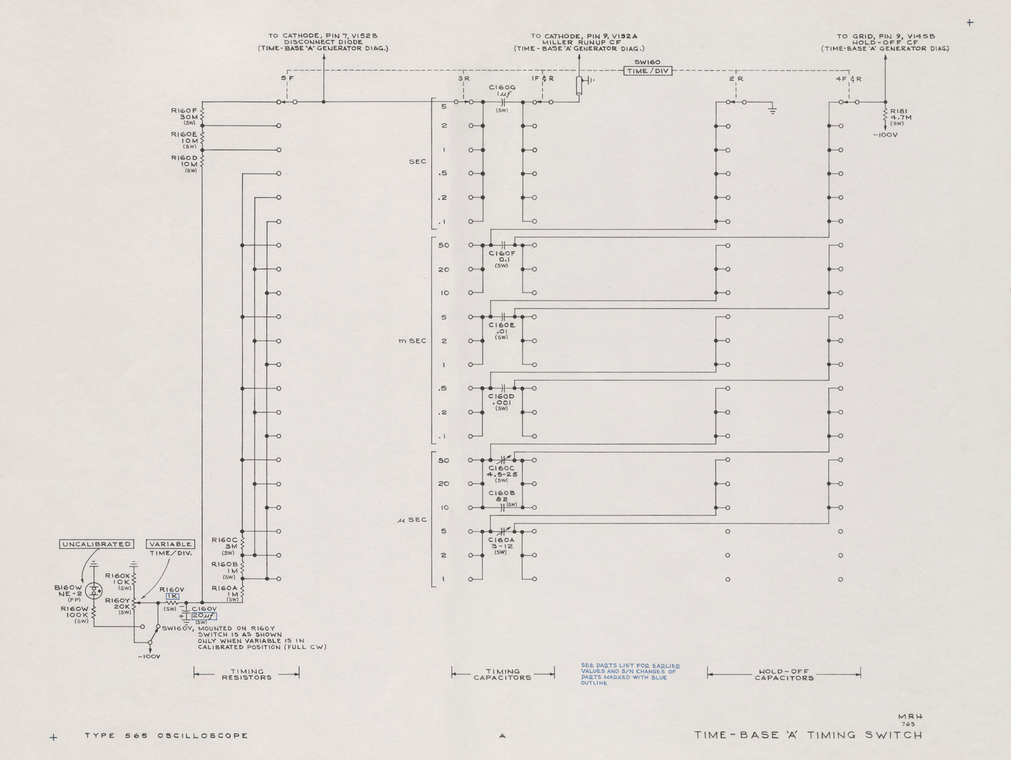
The current through the timing resistor, R160, is now diverted and begins to charge the timing capacitor, C160. As the timing capacitor charges, the grid of V161A goes negative.
The greatly amplified positive-going change at the plate of
V161A is coupled to the grid of V161B through the neon
lamp, B167. The neon lamp lowers the dc level of the signal
by about 60 volts, but does not reduce the signal amplitude.
The cathode of V161B provides the sawtooth output signal plus feedback to two points within the time base generator.
Feedback to the timing capacitor opposes the negative-
going change at the grid of V161A. This action persists
throughout the period of the sawtooth and limits the total
change in grid voltage to less than one volt. Since the
voltage drop across the timing resistor is held nearly
constant, the current through the resistor is essentially a
constant value. This constant current flows into the timing
capacitor and the voltage across the capacitor increases at a very linear rate. The rate of rise of the sawtooth is a function of the RC time constant of the timing resistor and
capacitor.
An attenuated sample of the positive-going output sawtooth is applied to the plate of V152C in the Hold-Off Circuit. The steady rise in voltage at the cathode of V152C charges the hold-off capacitor while raising the grid voltage on V145B. When the sawtooth has reached about one-half
its final amplitude, V145B begins to conduct. As the sawtooth continues to rise, the cathode of V145B and the grid of V135A also rise. V135A will begin to conduct when its grid has risen about 20 volts. The plate voltage on V135A and the grid voltage on V145A drop and the cathode current no longer required by V145A is assumed by V135A. This positive feedback rapidly drives V135A into heavy conduction and V145A into cut off.
The negative-going voltage step at the cathode of V135B
blanks the crt and forms the end of the + Gate Out pulse.
The positive going voltage step at the screen grid of V145A is coupled to the appropriate vertical plug-in unit to cause
a multi-trace plug-in unit, operating in the “alternate” mode, to switch channels.
When V145A cuts off, its plate voltage rises sharply to
about -3 volts and brings V152B into conduction. The grid
voltage on V161A rises and its plate voltage drops, carrying the grid and cathode of V161B with it. When the cathode of V161B drops to about -3.5 volts, V152A conducts to clamp the sawtooth output bus at that voltage level.
A sample of the falling voltage at the cathode of V161B
is coupled to the plate of V152C, cutting off its conduction.
While the hold-off capacitor was charged through the diode,
it must discharge through a large resistor, R181. This
retarded discharge (holdoff) delays the fall in voltage at the
grid (and hence, the cathode) of V145B. The STABILITY
control voltage divider network cuts off V145B when its
cathode drops to about -50 volts. Thus, V135A is reduced
from a stale of heavy conduction to its original quiescent
(triggerable) state.
Triggerable pulses which may arrive at the grid of V135A
while the sweep is in progress have no effect since V135A
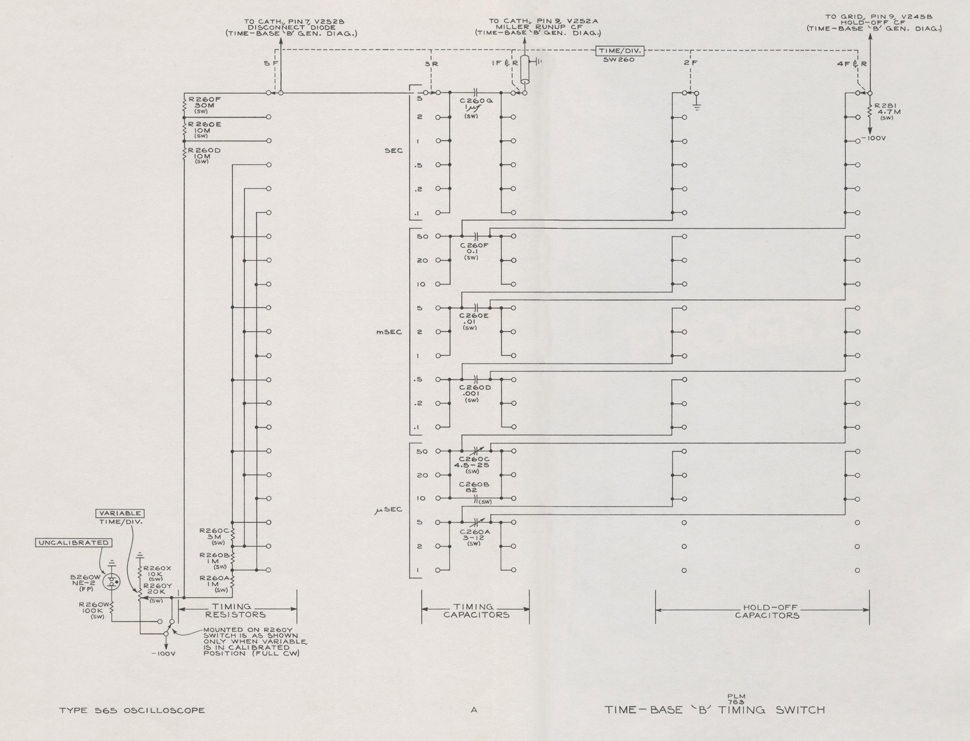
is already deep in cut off. When V135A is driven into heavy conduction at the peak of the sawtooth, trigger pulses still have no effect because their fixed amplitude is too low to bring V145A out of cut off. The Hold-Off Circuit extends this period of insensitivity and thus blocks the start of the
next cycle until the circuits have stabilized. Hold off time is required for stable triggering and is related to the timing capacitor being used. The proper holdoff capacitor is selected by the TIME/DIV. switch (see the Timing Switch
schematic).
Special Component Functions—C141 assures that the
Sweep-Gating Multivibrator will switch rapidly from one
conduction state to the other. R187 and R189 isolate the
shunt capacitance of the unblanking cables from the
Sweep-Gating Multivibrator so its switching speed is not degraded.
C165 aids V161B in charging the shunt capacitance in its
cathode circuit at the fastest sweep rates. C167 insures that the voltage divider consisting of B167 and R167 will have the proper frequency response. The SWEEP LENGTH control, R178, is set during calibration for the proper
sawtooth amplitude. D131 clips the positive-going portion of the triggering signal and C130 bypasses it to ground.
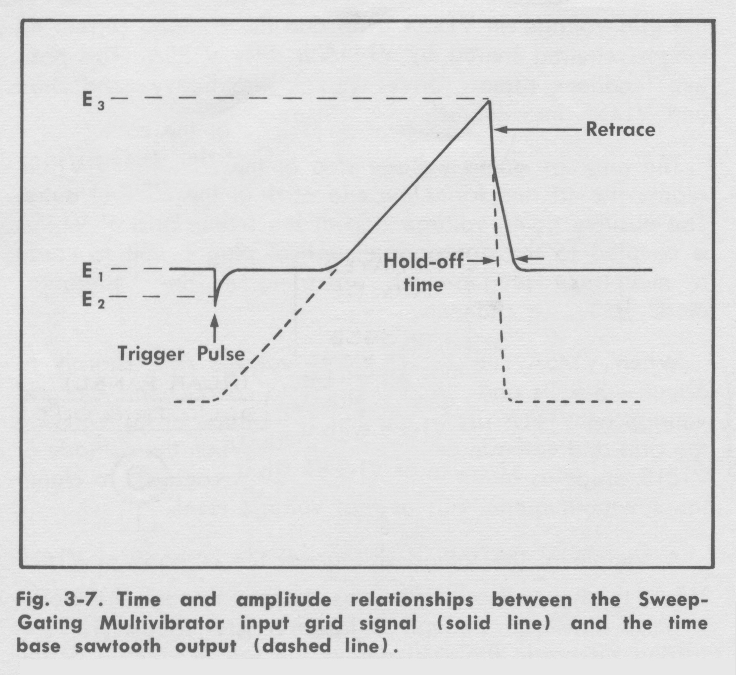
STABILITY control—Fig. 3-7 shows the relationship between the voltage at the Sweep-Gating Multivibrator input grid and the sawtooth output of the time base. Normally, the STABILITY control is set near mid-range so the voltage at the Sweep-Gating Multivibrator input grid will be at the level represented by E2 in Fig. 3-7. This voltage level is about 2 volts above the trip level (E1) required to cause the multivibrator to switch states. An incoming trigger from the Time Base Trigger circuit will drive the grid below the trip level.
The multivibrator will immediately switch states and a
sawtooth cycle will begin.
When the output sawtooth has reached about one-half of
its final amplitude, the Hold-Off Cathode Follower begins to conduct and raises the voltage on the Sweep-Gating Multivibrator input grid. The voltage continues to rise until it reaches the reset level represented by E3. At this level, the
multivibrator resets to its previous state and the retrace portion of the sawtooth begins. The falling voltage at the
input grid of V135A is retarded by the Hold-Off circuit, but
finally stabilizes at the quiescent level, E2. The entire circuit
is then ready for the next trigger pulse.
As you will note from the foregoing description and Fig. 3 7, the stability voltage at the Sweep Gating Multivibratar
input grid must be at the correct level for triggered operation to occur. As the STABILITY control is turned
counterclockwise, the quiescent voltage will become more positive than E2. The amplitude of the trigger pulses will then be insufficient to drive the grid through the trip level E1. Sincethe time base will not operate, this condition is referred to as “lockout”. As the STABILITY control is turned clockwise, the voltage becomes more negative than the trip level E2, and the Sweep-Gating Multivibrator will switch without waiting for a trigger pulse. As the sawtooth cycle thus initiatedcarries the input grid of the multivibrator through the retrace and hold-off period, the voltage will again fall below the trip level. Thus, another cycle will be initiated.
The sweep generation will repeat without the need for trigger pulses as long as the voltage from the STABILITY
control is sufficiently negative. This condition is referred to as ‘free run’ and can also be obtained by setting the LEVEL
control to the FREE RUN position (provided UPPER HORIZ. DISPLAY is set to ‘A’ TIME BASE)».
§§§
Il testo prosegue nella settima parte.
Per consultare le altre schede dedicate a questo oscilloscopio esposto al museo MITI (su proposta di Fabio Panfili) scrivere “565” su Cerca.
Elaborazioni e testo a cura di Fabio Panfili.
Per ingrandire le immagini cliccare su di esse col tasto destro del mouse e scegliere tra le opzioni.