
 Oscilloscopio a tubo catodico Tektronix Type 515A serial 005869. Quarta parte.
Della Tektronix, Inc. Portland, Oregon, Usa. Nell’inventario D del 1956, in data aprile 1961, al n° 1899 si legge: “Imp. Silvestar-Milano – Oscilloscopio Tektronix tipo 515A. Destinazione Elettronica. ₤ 840000”.
Il testo continua dalla terza parte.
§§§
«SECTION 3
CIRCUIT
DESCRIPTION
BLOCK DIAGRAM DESCRIPTION
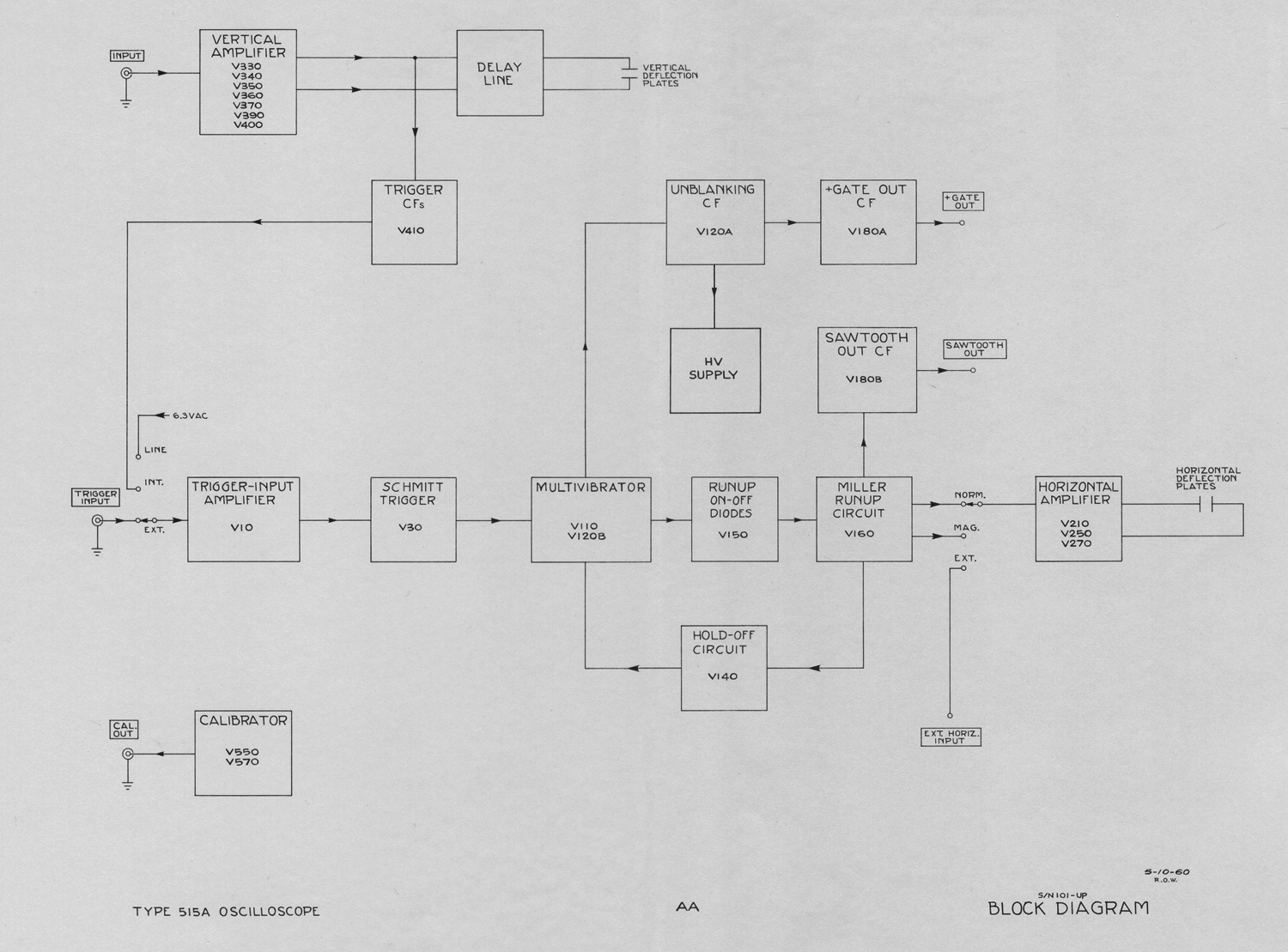
The block diagram shows the interconnection of the functional parts of the oscilloscope, except the power supplies. Functions of the switches are shown instead of their actual connections. This diagram, as well as the ones which follow, is designed to fold out so that the diagram can be studied along with the text without turning any pages.
The vertical amplifier has a sensitivity of .05 volt per centimeter (.1 volt per centimeter S/N 101-1000) and provides push-pull output to drive the deflection plates. The balanced delay line is connected between the output amplifier and the deflection plates.
The trigger cathode follower applies a sample of the vertical signal to the trigger-amplifier stage to provide internal triggering.
The trigger amplifier and shaper provide a sharp trigger pulse which triggers the multivibrator. The multivibrator gates the time-base generator and is prevented from recycling by the holdoff cathode follower until the generator has had time to run up and return.
The time-base generator is a Miller run-up type and provides a 150-volt sawtooth for the horizontal amplifier.
The horizontal amplifier converts the time-base
sawtooth for push-pull applications to the deflection plates.
The unblanking cathode follower applies a positive gate to the crt grid via the high-voltage power supply. It also supplies a gate to the gate-out cathode follower which provides a positive gate at a front-panel binding post.
The calibrator provides a square wave of known amplitude for checking the gain of the oscilloscope amplifiers and auxiliary equipment.
VERTICAL-DEFLECTION SYSTEM
General
The Type 515/515A vertical amplifier has a maximum sensitivity of .05 volt per centimeter (.1 volt per centimeter S/N 101-1000), ac or 1.The circuit consists of two stages of amplification, each stage preceded by cathode followers.
Input Connectors
There are two input connectors which can be switched into the input circuits by SW 301, the INPUT SELECTOR switch. This switch is wired physically so as to reduce coupling between inputs to a minimum. Blocking capacitor C301 is shorted out in the DC positions of the selector switch.
lnput Attenuators
The VOLTS/CM switch inserts frequency-compensated attenuators into the input circuit. Four attenuators are used singly or in tandem pairs to produce nine fixed sensitivities.
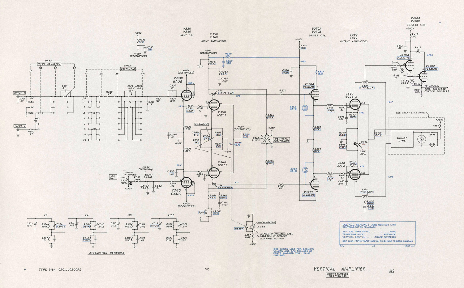 DC Balance
The DC BAL control, R338, provides an adjustable, dc grid voltage for V340 so that the cathode of V360 is at the same potential as the cathode of V350. When this control is properly set, no change in vertical positioning will result when the VARIABLE position is rotated.
Input Cathode Follower
The input cathode follower, V330, isolates the input circuits from changes in capacitance as the VARIABLE control is rotated. R330 is a current-limiting resistor to limit grid current in the event an excess voltage is applied to the input. The opposite cathode follower, V340, balances the drift in V330 caused by heater-voltage changes.
Input Amplifier
The input amplifier stage is a common- cathode phase-splitter amplifier. Coils L351 and L361 provide high-frequency peaking. The VARIABLE VOLTS/CM control, R356, varies the gain by varying the degeneration in the
cathode circuit.
Vertical positioning is produced by two dual potentiometers, R368, connected to the plates of the amplifier so that current through one plate load is increased as current through the other plate load is decreased. Since the
amplifier is dc coupled, the change in the plate voltage which occurs changes the position of the trace on the cathode-ray tube.
The rc networks, R352, C352 and R362, C362, provide compensation for the reduction in gain at very-low frequencies which is a characteristic of high-conductance amplifiers.
Output Amplifiers
Cathode followers V370A and V370B drive the output amplifiers through series peaking coils L390 and L400. The GAIN ADJ. control, R396, sets the gain of the amplifier to agree with the front-panel calibration. Plate current
for the output amplifiers is supplied by the delay-line termination resistors , R485 and R486.
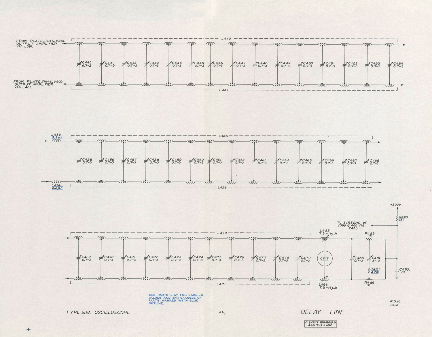
Delay Line
The balanced delay line delays the signal until the sweep starts and the crt is unblanked.
The trigger signal is taken from a coil which serves as the first section of the delay line.
Each section of the line is turned for optimum response to a square wave.
HORIZONTAL-DEFLECTION SYSTEM
Trigger Amplifier
The TRIGGER SELECTOR switch with the black knob, SW20, selects the source of triggering voltage and arranges the trigger-amplifier input circuit to produce negative-going output for either negative-going or positive-going
portions of the input signal.
The trigger amplifier, V10, is a grounded-grid cathode-coupled amplifier. A capacitor, C4, can be switched into the grid circuit to remove the dc component of the trigger signal.
Output is always taken from the pentode plate, but the TRIGGER SELECTOR switch connects either the pentode grid or the triode grid to the input-signal source. The opposite grid is connected to a dc bias source, adjustable by
means of the TRIGGERING LEVEL control.
This bias voltage determines the voltage on the pentode plate. In the AC and DC positions of the TRIGGER SELECTOR switch, the voltage on the pentode plate is dc coupled to the grid of V30A.
Trigger Shaper
The trigger-shaper stage consists of V30 connected as a dc-coupled multivibrator. In the normal, or quiescent, state the V30A section is conducting and its plate is down. The grid
of the V30B section is dc coupled to the V30A plate through divider R38, R39 and R40, which holds the “B” grid below plate-current cutoff.
As the trigger signal drives grid of V30A in the negative direction the cathodes of both tubes follow the grid down until V30B starts to conduct. At this point the plate voltage of V30A and the B grid rises with it. The V30B cathode rises with its grid carrying the “A” cathode with it and V30A cuts off.
The transition occurs very rapidly, regardless of how slowly the V30A grid signal falls.
The steep negative-going step at the plate of V30B is differentiated by an rc network including C109 shown in the sweep diagram, and the sharpened pulse trips the sweep multivibrator.
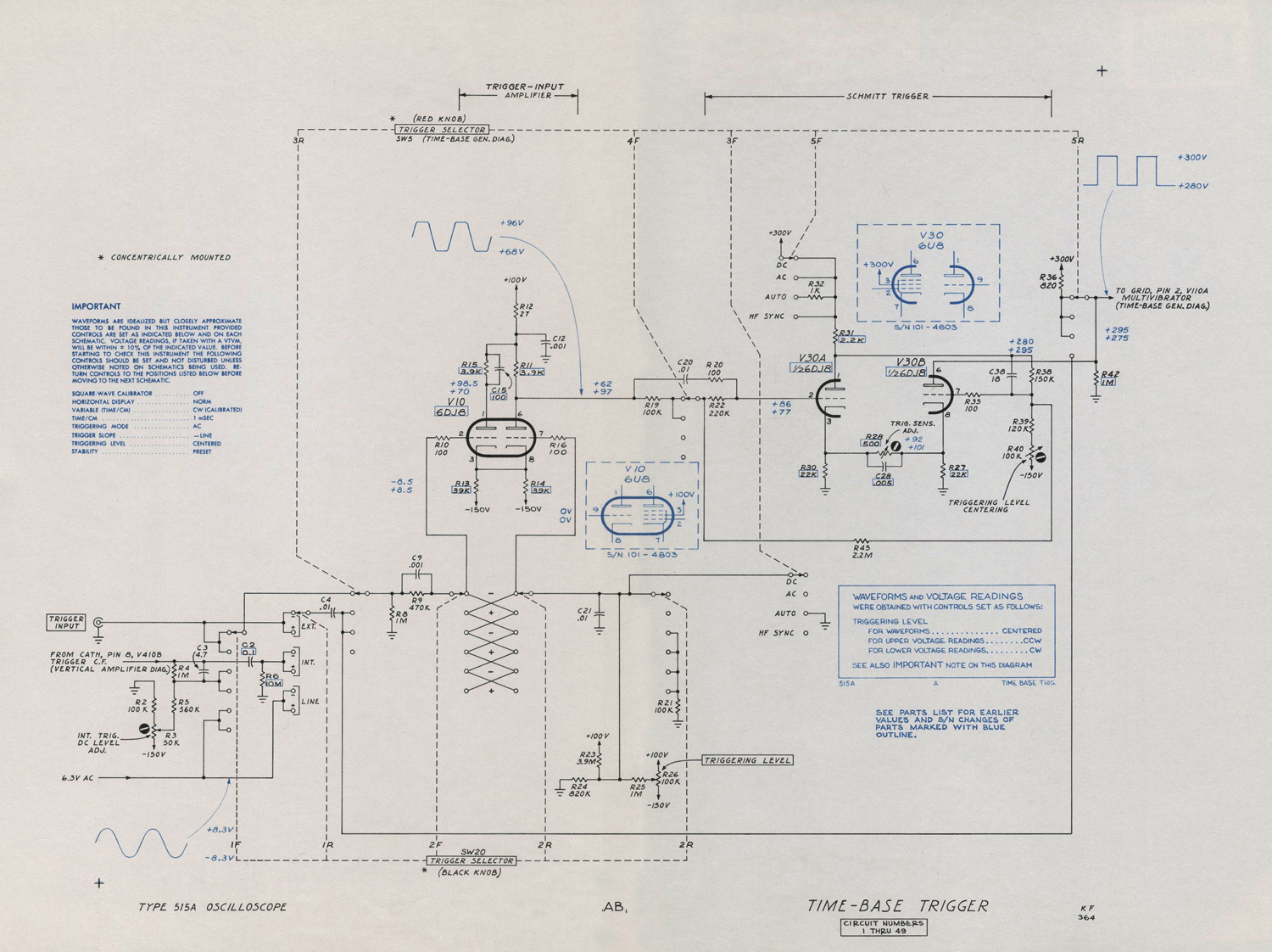
Trigger Mode Switch
The TRIGGER SELECTOR switch with the red knob, SW5, has four positions which arrange the circuits for four types, or modes, of triggering. In the DC position, the triggering signal is dc coupled as far as the trigger-shaper
stage. In the AC position, blocking capacitor C4 removes the dc component of the signal.
In the AUTO. position of SW5, the plate of the A section of the trigger shaper, V30, drives the grid of the B section just as it also drives its own grid through R45 , a resistance of several megohms. This plate-to-grid coupling allows the trigger shaper to free-run when no triggering signal is present. The presence of R45 causes the trigger shaper to free run when no trigger signal is present. For example,
when the plate of V30A rises, the grid of V30B also rises, carrying with it the right-hand end of R45. The left-hand end of R45 is connected to the A grid through R22. The
time constant of the rc circuit between the B grid and ac ground through C20, R22 and R45 is of such length that it takes about .01 second for the V30A grid to rise exponentially from its starting point below cutoff to a point where plate current can flow.
When V30A plate current flows, the plate drops, forcing the V30B grid down, and thus the right-hand end of R45 is forced down.
The left-hand end of R45 and the A grid immediately begin to drop exponentially toward cutoff. When the A grid reaches cutoff again it has completed one cycle of the approximately 50-cycle triangular waveform. The range of
the V30A grid voltage between A cutoff and B cutoff is about 3 volts for the circuit used in the AUTO. mode. This is increased from about .5 volt for the AC and DC modes by the addition of R45 to the circuit.
Since the V30A grid is never more than 3 volts from cutoff, a trigger signal with a peak-to-peak voltage of three volts or more can drive the grid to cutoff at any time and produce a trigger output. Smaller signals can also trigger the shaper but only if they occur at a time when the grid is within their peak voltage of cutoff. The duty cycle of operation of the time-base generator is somewhat reduced therefore with smaller trigger signals.
This circuit configuration is useful because with it the time-base generator can be synchronized with repetitive signals over a wide range of frequencies without readjustment. When not triggered externally, the generator continues at a 50-cycle rate, and in the absence of any vertical signal, generates a base line that shows that the oscilloscope is adjusted so as to display any signal that might be connected to the vertical-deflection system.
In the H F SYNC position of SW5, the trigger amplifier and trigger shaper stages are bypassed and the trigger signal is applied directly to the sweep multivibrator. In this mode the STABILITY control is set so the sweep is superimposed on the negative-going trigger-holdoff waveform at the grid of V110A and will cause the multivibrator to synchronize at a submultiple of the triggering signal frequency. This circuit is suitable for signals in excess of five megacycles.»
§§§
Il testo prosegue nella quinta parte.
Per consultare le parti dedicate a questo oscilloscopio scrivere: “515A” su Cerca.
Foto di Claudio Profumieri, elaborazioni, ricerche e testo a cura di Fabio Panfili.
Per ingrandire le immagini cliccare su di esse col tasto destro del mouse e scegliere tra le opzioni.