
 3305A SWEEP PLUG-IN per il 3300A FUNCTION GENERATOR della HEWLETT PACKARD GMBH. Matr. N° G 348-00120. Seconda parte.
Nell’inventario per reparto N° 7 di Elettronica, in data febbraio 1968, al n° D 4236 si legge: “A FUNCTION GENERATOR S. 3300 A – HP” ; e la n° D 4236 si legge: “A AUXILIARY PLUG-IN 3301 – HP”, ma forse si tratta del mod. 3305!
È facile trovare le istruzioni in internet agli indirizzi elencati sotto.
http://bee.mif.pg.gda.pl/ciasteczkowypotwor/HP/3300A.pdf
http://hpmemoryproject.org/wb_pages/wall_b_page_10c.htm
http://www.kennethkuhn.com/students/ee431/mfg_data/hpj_nov_1965.pdf
http://www.hpl.hp.com/hpjournal/pdfs/IssuePDFs/1968-05.pdf
Il testo prosegue dalla prima parte.
§§§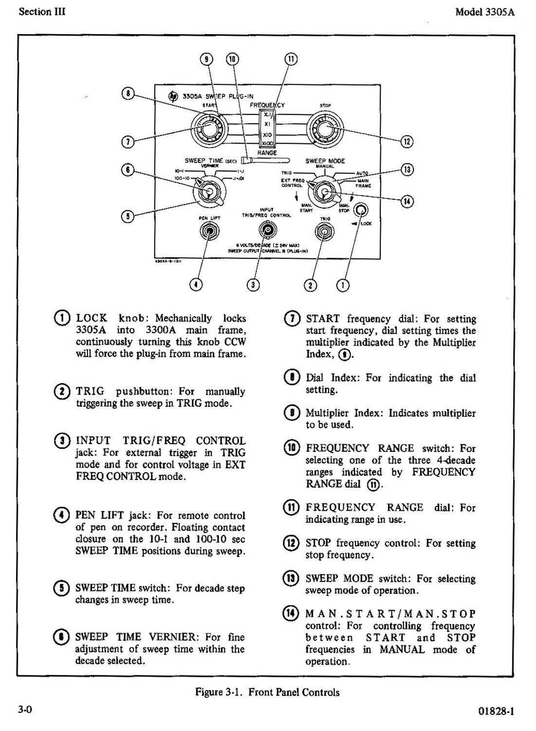 FIGURE 3-1 FRONT PANEL CONTROLS
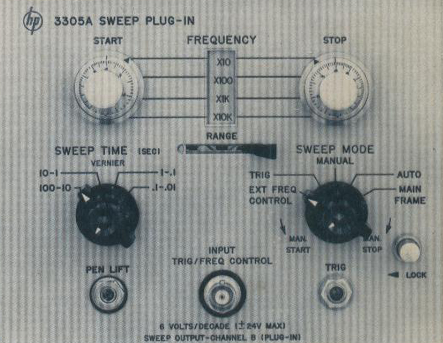
(1) LOCK knob: Mechanically locks 3305A into 3300A main frame, continuously turning this knob CCW will force the plug-in from main frame.
(2) TRIG pushbutton: For manually triggering the sweep in TRIG mode.
(3) INPUT TRIG/FREQ CONTROL jack: For external trigger in TRIG mode and for control voltage in EXT FREQ CONTROL mode.
(4) PEN LIFT jack: For remote control of pen on recorder. Floating contact closure on the 10-1 and 100-10 sec SWEEP TIME positions during sweep.
(5) SWEEP TIME switch: For decade step changes in sweep time.
(6) SWEEP TIME VERNIER: For fine adjustment of sweep time within the decade selected.
(7) START frequency dial: For setting start frequency, dial setting times the multiplier indicated by the Multiplier Index, (9).
(8) Dial Index: For indicating the dial setting.
(9) Multiplier Index: Indicates multiplier to be used.
(10) FREQUENCY RANGE switch: For selecting one of the three 4-decade ranges indicated by FREQUENCY RANGE dial (11)
(11) FREQUENCY RANGE dial: For indicating range in use.
(12) STOP frequency control: For setting stop frequency.
(13) SWEEP MODE switch: For selecting sweep mode of operation.
(14) MAN. START/MAN.STOP control: For controlling frequency between START and STOP frequencies in MANUAL mode of operation.
«SECTION III
OPERATING INSTRUCTIONS
3-1. INTRODUCTION.
3-2. This section contains instructions and information necessary for operation of the Model 3300A/3305A Function Generator with the Sweep Plug-in.
3-3. FRONT PANEL CONTROLS.
3-4. The 3305A front panel controls are identified and described in Figure 3-1. Refer to the 3300A Operating and Service Manual for the function of the 3300A main frame controls.
3-5. MODES OF OPERATION.
3-6. The Model 3300A/3305A has five modes of operation. Each n-rode of operation is described in the paragraphs listed:
1.AUTO (Paragraph 3-35)
2.TRIGGER (Paragraph 3-30)
3.EXTERNAL FREQUENCY CONTROL (Paragraph 3-33)
4.MANUAL (Paragraph 3-36)
5.MAIN FRAME (Paragraph 3-39)
3-7. GENERAL OPERATING INFORMATION.
3-8. WARM-UP TIME.
3-9. After inserting the Plug-in into the main frame, apply operating power by depressing POWER pushbutton and allow a one hour warm up and stabilization period for internal parts to reach normal operating temperature; specified accuracy will then be obtained. If the main frame has been on for one hour or more prior to inserting the 3305A Plug-in, the warm-up time may be decreased to 20 minutes.
3-10. TYPE OF SWEEP.
3-11. The sweep generated by the 3300A 3305A is logarithmic. That is, the amount of time required to sweep each decade is equal; therefore, the rate of change in output frequency increases as the sweep progresses.
3-12. SWEEP OUTPUT VOLTAGE.
3-13. In all modes of operation except EXT FREQ CONTROL and MAIN FRAME, a sweep voltage proportional to the log of the output frequency is available from CHANNEL B OUTPUT in PLUG-IN position. This sweep voltage may be used to obtain proper pen movement or oscilloscope presentation in AUTO, TRIG, or MANUAL modes of operation. The Channel B AMPLITUDE control adjusts the amplitude of the sweep output voltage. Once the sweep output voltage is adjusted the sweep width may be varied without affecting the sweep output voltage amplitude or period. The sweep time may be changed without readjusting the sweep output amplitude. The period of the sweep output will be the same as the sweep time.
3-14. PEN LIFT.
3-15. In the 100-10 and 10-1 sec SWEEP TIME positions the PEN LIFT jack provides contact closure during the sweep for remote control of recorder pen. In the 1-.1 and .1-.01 sec SWEEP TIME positions the PEN LIFT circuit is switched out.
3-16. SWEEP TIME.
3-17. In AUTO or TRIG mode of sweep the length of time required for one sweep from START frequency to STOP frequency is determined by the SWEEP TIME switch and VERNIER settings. Sweep time is continuously adjustable from .01 seconds to 100 seconds in four decade steps. In each decade position, sweep time is longest when the VERNIER is fully counterclockwise. Sweep time may be measured by observing the period of the sweep output voltage.
3-18. SWEEP WIDTH.
3-19. In AUTO, TRIG, or MANUAL, the sweep width is controlled by the FREQUENCY RANGE switch in conjunction with the START and STOP controls. For example, to set the start frequency to 50 HZ, the START control should be turned until the 5 is aligned with the Dial Index, Figure 3-1, and the Multiplier Index (9), is aligned with the X10 marking on the FREQUENCY RANGE dial. The stop frequency is set in the same manner. See Paragraph 3-33 for external sweep width control.
3-20. When the Multiplier Index is in transition between two multipliers, use the larger multiplier when the dial is above 1 and the smaller multiplier when the dial is below 1.
3-21. SWEEP DIRECTION.
3-22. The START and STOP controls may be set to sweep either up or down in frequency. When sweeping down there is a slight discontinuity caused by internal switching at the midpoint of each frequency range, 10 Hz on X.1-X100, 100 Hz on X1-X1K and l kHz on X10-X10K. When sweeping down less than two decades, this discontinuity can be avoided by selecting the proper frequency range setting. For example a sweep from 900 Hz down to 20 Hz does not go through the switch point on the highest or lowest FREQUENCY RANGE setting. This feature is available because of the overlapping of the three frequency ranges.
3-23. When sweeping up, this internal switching is negligible; however, when sweeping high Q circuits over a narrow band, it is recommended to use the overlapping range feature and select a range where the mid-range switch-point is not within the range of frequencies being swept.
3-24. OPERATING PROCEDURES.
3-25. AUTO.
3-26. In AUTO mode the output of the 3300A is repetitively swept from the start frequency to the stop frequency. The maximum sweep width is 4 decades. The lowest FREQUENCY RANGE switch position will enable sweeping from 0.1 Hz to 1 kHz. The middle FREQUENCY RANGE switch position will enable sweeping from 1 Hz to 10 kHz. The highest FREQUENCY RANGE switch position will enable sweeping from 10 Hz to 100 kHz.
3-27. The sweep width of any frequency range may be reduced as desired by setting the START and STOP controls away from their limits. If the START control is set at a higher frequency than the STOP control, the 3300A will sweep downward.
3-28. Any sweep time between .01 seconds and 100 seconds may be selected by the SWEEP TIME switch and vernier. A sweep voltage output for driving a recorder or an oscilloscope is available from the 3300A CHANNEL B OUTPUT PLUG-IN position. Refer to Paragraph 3-12 for additional information concerning sweep output voltage.
3-29. To operate the 3300A/3305A in AUTO SWEEP MODE proceed as follows:
1.Set the SWEEP MODE switch to AUTO.2.Set the SWEEP TIME switch and the VERNIER to the desired sweep time.
3.Set the START and STOP controls and the FREQUENCY RANGE switch to the desired frequencies.
4.Position CHANNEL A or CHANNEL B to the desired function and adjust the AMPLITUDE control for the desired output level.
5.Connect the device under test to the CHANNEL A or CHANNEL B OUTPUT jack.
6.If a sweep drive voltage is desired, connect the recorder X axis input or oscilloscope horizontal input to CHANNEL B OUTPUT. Switch the CHANNEL B function switch to PLUG-IN. Adjust the CHANNEL B AMPLITUDE control for the desired display on the oscilloscope or recorder.
NOTE:
The MANUAL sweep mode may be used to set the X and Y limits on a
recorder or oscilloscope before switching to AUTO3-30. TRIGGER.
3-31. In TRIG mode, the 3305A operates the same as in AUTO except that it must be triggered for each sweep. Triggering may be accomplished by depressing the TRIG button or by applying a positive external trigger to the INPUT TRIG/FREQ CONTROL jack. The external trigger is ac coupled and must be positive-going, at least 1V peak with 2V per msec rise rate. The maximum trigger rate in TRIG sweep mode is 60 Hz.
3-32. To operate the 3300A/3305A in TRIG SWEEP MODE proceed as follows:
1.Set the SWEEP MODE switch to TRIG.
2.Set the SWEEP TIME switch and VERNIER to the desired sweep time.
3.Set the START and STOP controls and the FREQUENCY RANGE switch to the desired frequencies.
4.Position CHANNEL A or CHANNEL B to the desired function and adjust the AMPLITUDE control for the desired output level.
5.Connect the device under test to the CHANNEL A or CHANNEL B OUTPUT jack.
6.If a sweep voltage is desired, connect the recorder X axis input or oscilloscope- horizontal input to the CHANNEL B OUTPUT. Switch the CHANNEL B function switch to PLUG-IN. Adjust the CHANNEL B AMPLITUDE control for desired display on oscilloscope or recorder.
7.If an external trigger voltage is to be used, connect the INPUT TRIG/FREQ CONTROL jack to a trigger source that will supply a positive-going trigger with an amplitude of at least 1 volt with a rise rate of 2 volts per msec or greater.
3-33. EXTERNAL FREQUENCY CONTROL.
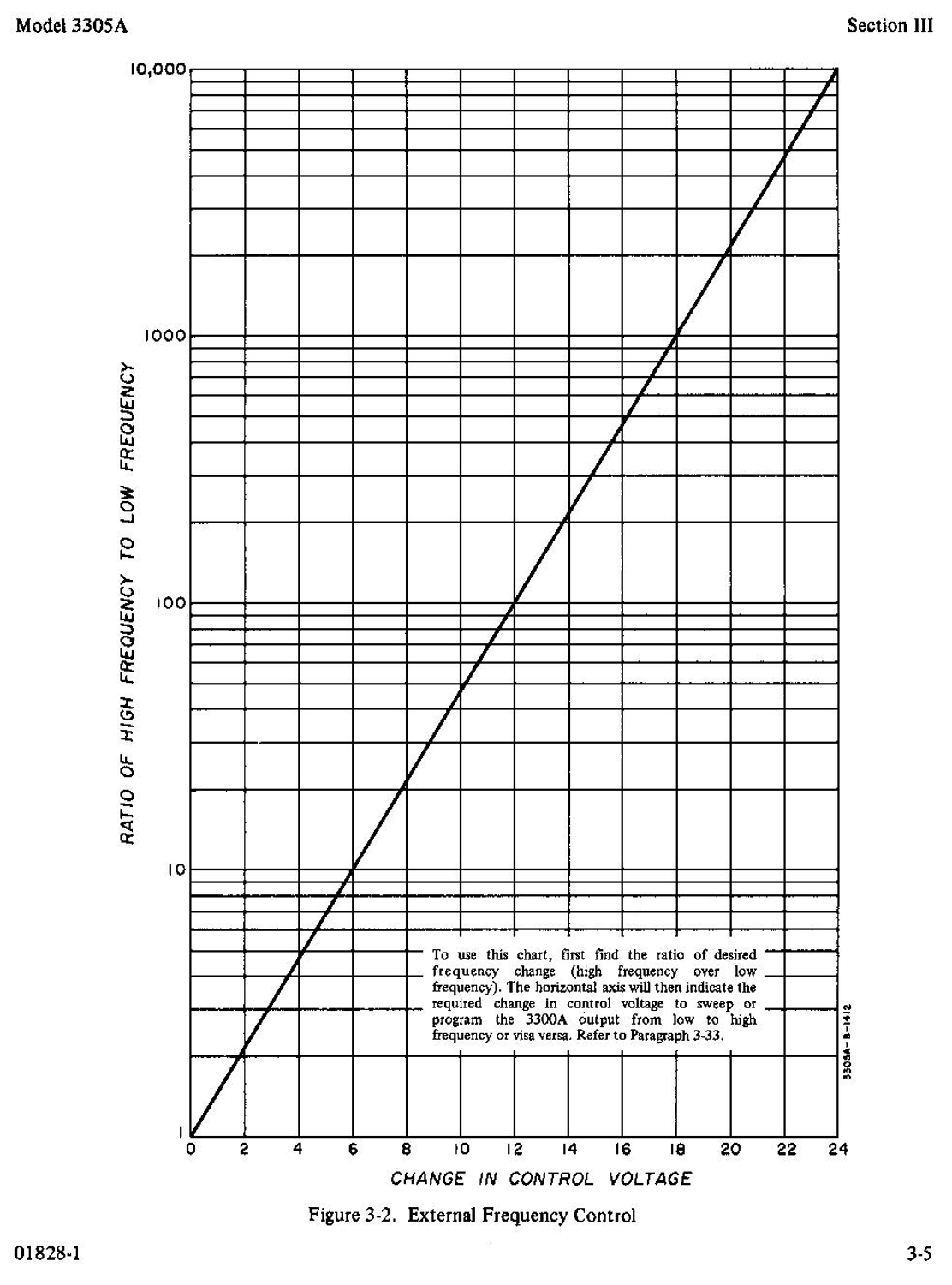
3-34. In EXT FREQ CONTROL the START control determines the initial start frequency, and the voltage applied to the INPUT TRIG/FREQ CONTROL varies the frequency from this initial frequency. For each +6 volts applied externally, the 3300A frequency increases one decade above the START frequency until the frequency range upper limit is reached. Each -6 volts applied decreases the frequency one decade until the frequency range lower limit is reached. The external voltage applied may be either ac or dc with a peak of less than +/- 24V. The maximum frequency of ac control voltage for external frequency control is 100 Hz.
NOTE:
The SWEEP TIME controls and STOP FREQUENCY control have no effect in EXT FREQ CONTROL mode.
3-35. To operate the 3300A/3305A in EXT FREQ CONTROL SWEEP MODE proceed as follows:
1.Set the SWEEP MODE switch to EXT FREQ CONTROL.
2.Set START control to the desired start frequency.
3.Connect an external control voltage to INPUT TRIG/FREQ CONTROL jack.
NOTE:
If a positive control voltage is used, set the START control to the lowest frequency desired. If a negative control voltage is used, set the START control to the highest frequency desired. If an ac control voltage is used, set the START control to the desired center frequency and adjust the peak amplitudes of the ac signal to set the high and low frequencies. The sensitivity of the external frequency control is 6V/decade. The change in external voltage required for change in frequency may be determined from Figure 3-2 or from the following formula:
V = 6V (log of high freq. – log of low freq.)
1.Position CHANNEL A or CHANNEL B to the desired function and adjust the AMPLITUDE control for the desired output level.
2.Connect the device under test to the appropriate CHANNEL A or CHANNEL B OUTPUT jack.
NOTE:
If the INPUT TRIG/FREQ CONTROL jack is open during EXT FREQ CONTROL mode the output frequency may vary with stray voltage pickup.
3-36. MANUAL.
3-37. In MANUAL, the 3300A output frequency is controlled by the MAN. START/MAN. STOP control. When the MAN. START/MAN. STOP knob is fully counterclockwise, the 3300A frequency is that of the START control. As the MAN. START/MAN. STOP knob is turned clockwise, the 3300A frequency varies toward the STOP setting; reaching the STOP frequency in the fully clockwise position.
3-38. To operate the 3300A / 3305A in MANUAL SWEEP MODE proceed as follows:
1.Set the SWEEP MODE switch to MANUAL.
2.Set the START and STOP controls and the FREQUENCY RANGE switch to the desired frequencies.
3.Position CHANNEL A or CHANNEL B to the desired function and adjust the AMPLITUDE control for the desired output level.
4.Connect the device under test to the appropriate CHANNEL A or CHANNEL B OUTPUT jack, and manually control the sweep with the MAN. START/MAN. STOP control.
5.If a sweep drive voltage is desired, connect the recorder X axis input or oscilloscope horizontal input to the CHANNEL B OUTPUT, and switch the CHANNEL B function switch to PLUG-IN. Adjust the CHANNEL B AMPLITUDE control for desired display on the oscilloscope or recorder.
NOTE:
The MANUAL mode of sweep permits the setting of start and stop frequency points with an electronic counter before switching to the AUTO or TRIG mode. The MANUAL sweep mode is also very useful in setting the X and Y limits on a recorder or oscilloscope.
3-39. MAIN FRAME.
3-40. In MAIN FRAME, the 3300A operates independently of the 3305A; however, the plug-in must remain in place in order to provide electrical connections for 3300A main frame operation.
NOTE:
Refer to the 3300A Operating and Service Manual for the operating procedure in MAIN FRAME».
 §§§
§§§
Continua nella terza parte.
Per consultare le altre schede scrivere “ 3305A” su Cerca. Per consultare le schede del generatore di funzioni 3300A scrivere “3300A”.
Foto di Claudio Profumieri, elaborazioni e ricerche di Fabio Panfili.
Per ingrandire le immagini cliccare su di esse col tasto destro del mouse e scegliere tra le opzioni.