 3305A SWEEP PLUG-IN per il 3300A FUNCTION GENERATOR della HEWLETT PACKARD GMBH. Matr. N° G 348-00120. Quinta parte.
Nell’inventario per reparto N° 7 di Elettronica, in data febbraio 1968, al n° D 4236 si legge: “A FUNCTION GENERATOR S. 3300 A – HP” ; e la n° D 4236 si legge: “A AUXILIARY PLUG-IN 3301 – HP”, ma forse si tratta del mod. 3305!
È facile trovare le istruzioni in internet agli indirizzi elencati sotto:
http://bee.mif.pg.gda.pl/ciasteczkowypotwor/HP/3300A.pdf
http://hpmemoryproject.org/wb_pages/wall_b_page_10c.htm
http://www.kennethkuhn.com/students/ee431/mfg_data/hpj_nov_1965.pdf
http://www.hpl.hp.com/hpjournal/pdfs/IssuePDFs/1968-05.pdf
Quel che segue è tratto dalle istruzioni della H-P conservate presso la Sezione Elettronica.
Il testo prosegue dalla quarta parte.
§§§
« SECTION VII CIRCUIT DIAGRAMS
7-1. INTRODUCTION.
7-2. This section contains the circuit diagrams necessary for the operation and maintenance of the Model 3305A Sweep Plug-in. Included are a functional block diagram, schematic diagrams, component location diagrams, and an adjustment point location diagram.
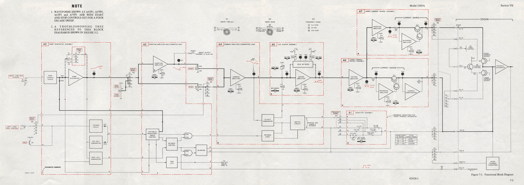
7-3. FUNCTIONAL BLOCK DIAGRAM.
7-4. The functional block diagram shows the relationship between the assemblies of the instrument. Signal flow between the Plug-in and the main frame is also shown on the functional block diagram.
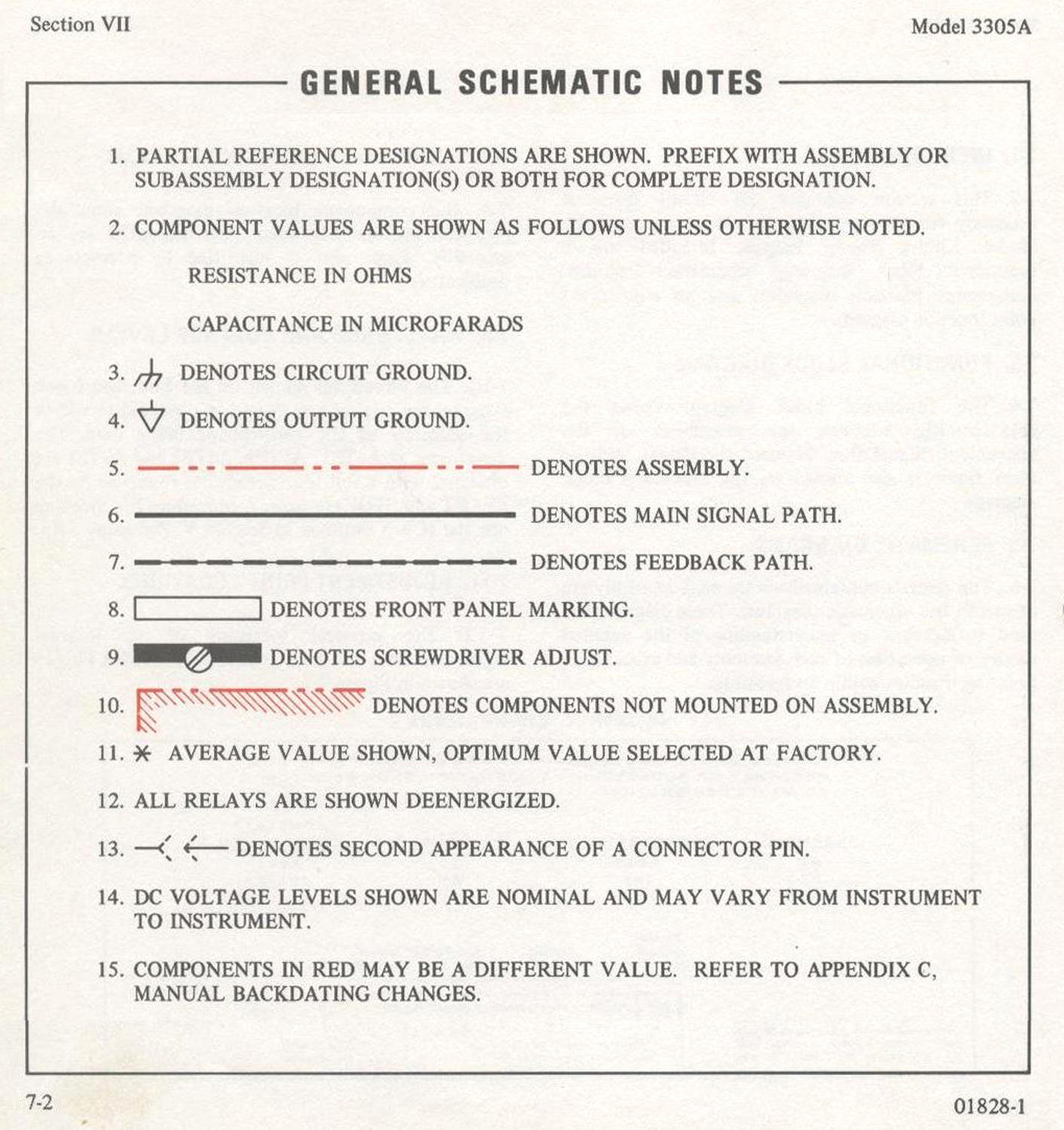
7-5. SCHEMATIC DIAGRAMS.
7-6. The circuits contained within each assembly are shown in the schematic diagrams. These diagrams are used to develop an understanding of the detailed theory of operation of each assembly and as an aid in isolating troubles within an assembly.
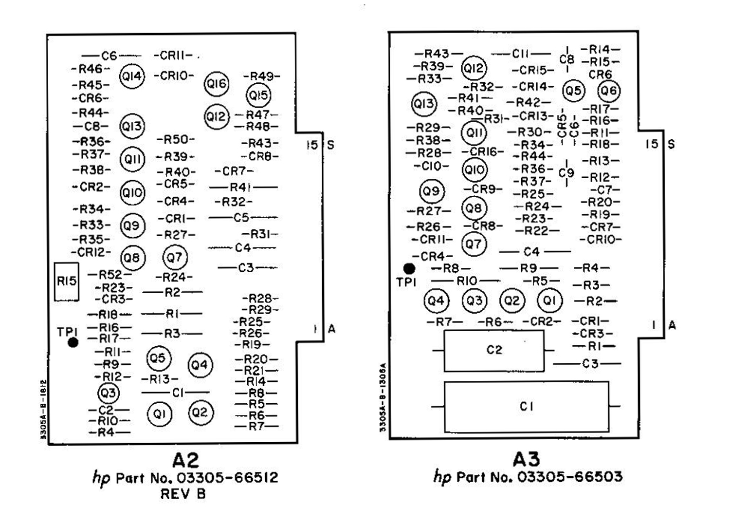
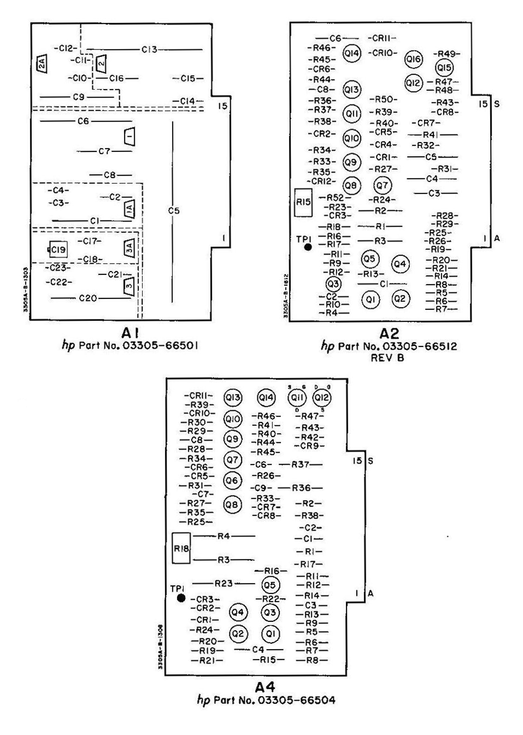
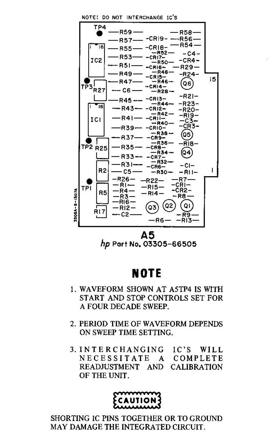
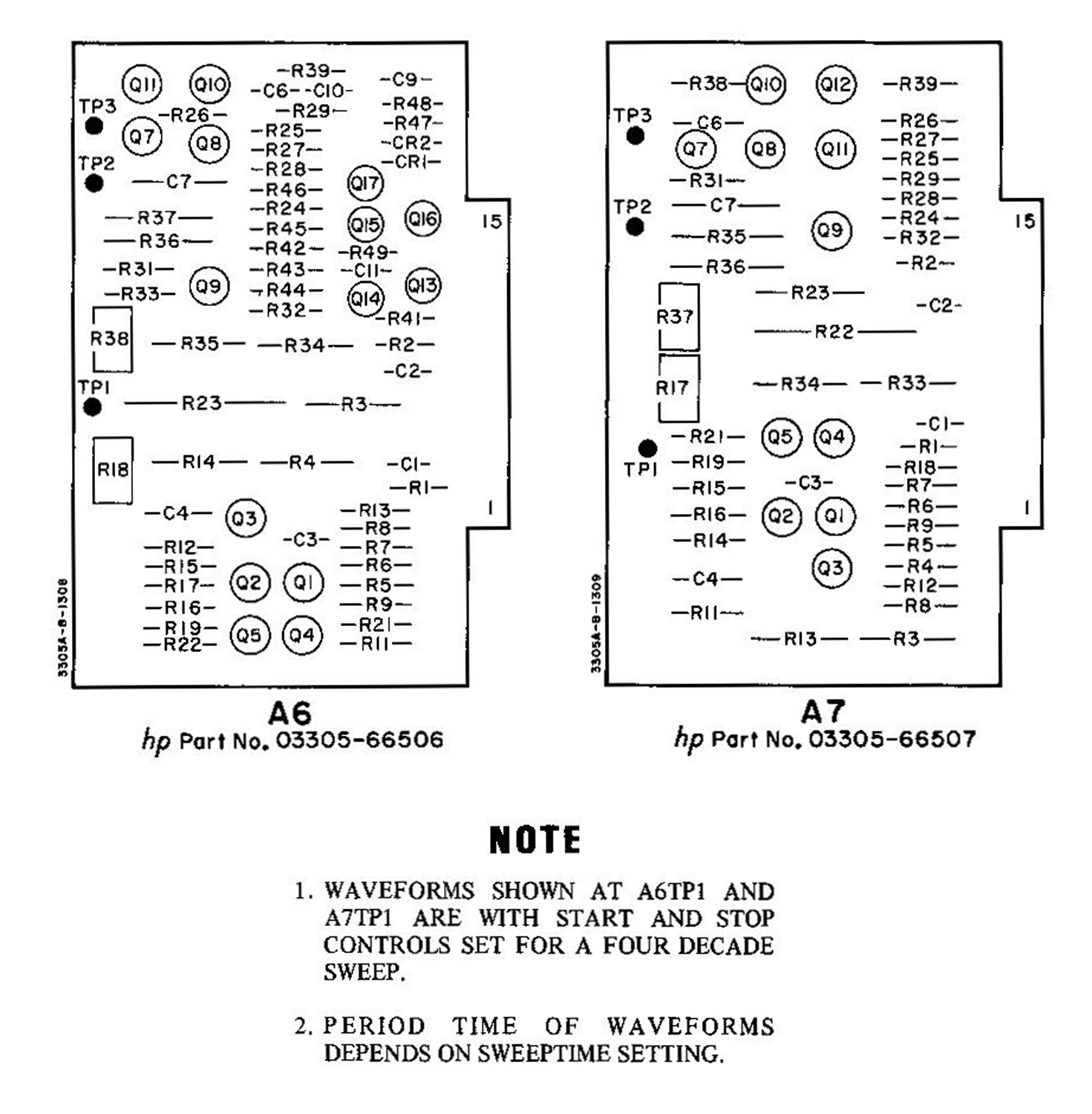
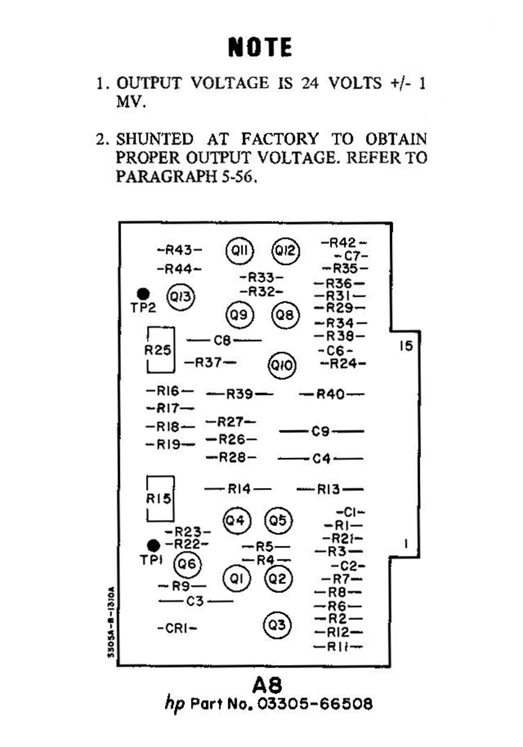
7-7. COMPONENT LOCATION DIAGRAMS.
7-8. The component location diagrams show the physical location of each part mounted on an assembly. Each part is identified by a reference designator.
7-9. WAVEFORMS AND VOLTAGE LEVELS.
7-10. The waveform shown on the Function Block Diagram are critical and should be observed to within the accuracy of the oscilloscope being used. The waveforms at A4TP1, A5TP4, A6TP1 and A7TPI are observed with a full four decades of sweep set by the START and STOP controls. A procedure for checking out the IC’s is outlined in Section V, Paragraph 5-45.
7-11. ADJUSTMENT POINT LOCATIONS.
7-12. The physical locations of all internal adjustment and test points within the 3305A Plug-in are shown in Figure 7-l.»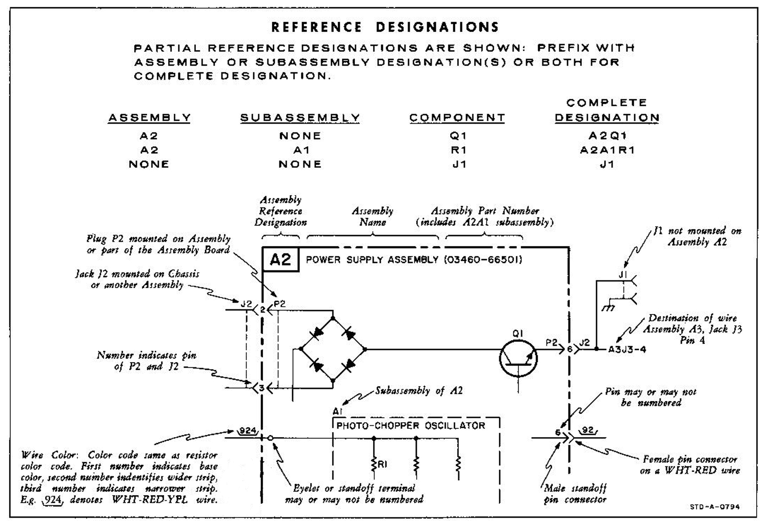
 Per consultare le altre schede scrivere “ 3305A” su Cerca. Per consultare le schede del generatore di funzioni 3300A scrivere “3300A”.
Foto di Claudio Profumieri, elaborazioni e ricerche di Fabio Panfili.
Per ingrandire le immagini cliccare su di esse col tasto destro del mouse e scegliere tra le opzioni.