
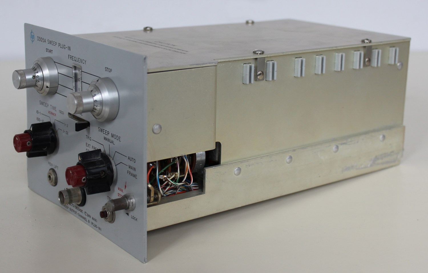
 3305A SWEEP PLUG-IN per il 3300A FUNCTION GENERATOR della HEWLETT PACKARD GMBH. Matr. N° G 348-00120. Terza parte.
Nell’inventario per reparto N° 7 di Elettronica, in data febbraio 1968, al n° D 4236 si legge: “A FUNCTION GENERATOR S. 3300 A – HP” ; e la n° D 4236 si legge: “A AUXILIARY PLUG-IN 3301 – HP”, ma forse si tratta del mod. 3305!
È facile trovare le istruzioni in internet agli indirizzi elencati sotto.
http://bee.mif.pg.gda.pl/ciasteczkowypotwor/HP/3300A.pdf
http://hpmemoryproject.org/wb_pages/wall_b_page_10c.htm
http://www.kennethkuhn.com/students/ee431/mfg_data/hpj_nov_1965.pdf
http://www.hpl.hp.com/hpjournal/pdfs/IssuePDFs/1968-05.pdf
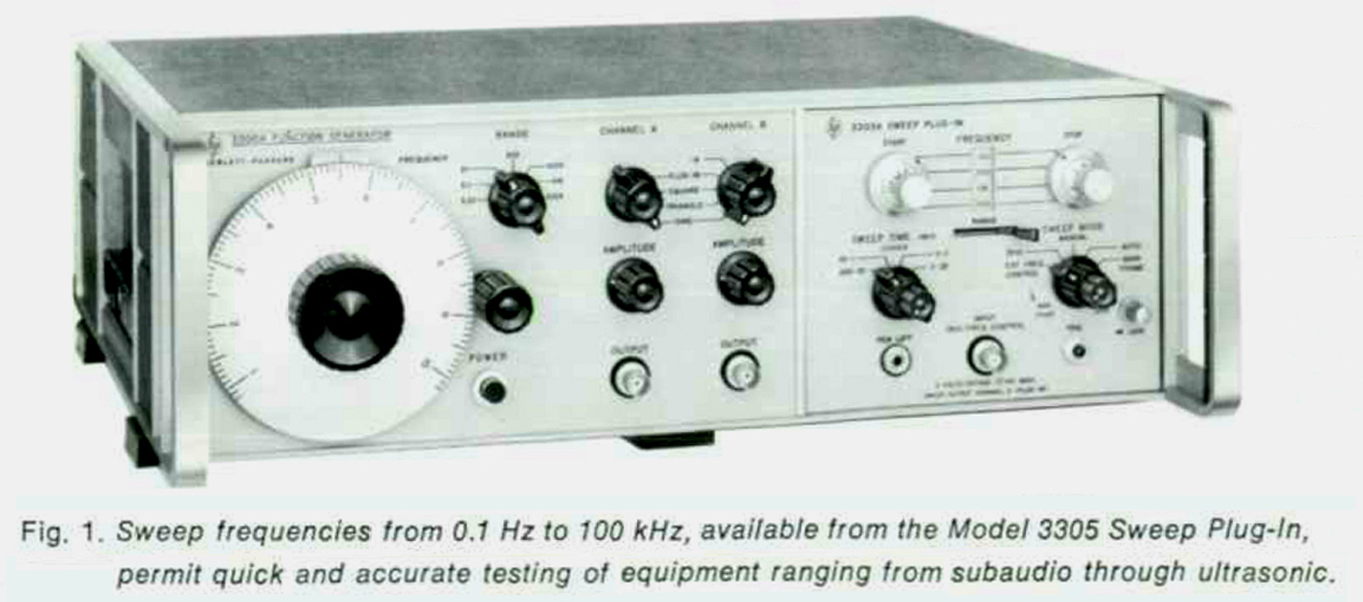
da cui è tratta la fig.1.
Quel che segue è tratto dalle istruzioni della H-P conservate nella Sezione Elettronica.
Il testo prosegue dalla seconda parte.
§§§
«SECTION IV
THEORY OF OPERATION
4-1. INTRODUCTION.
4-2. This section contains a general theory of operation for the -hp- Model 3305A Sweep Plug-in. Included is a block diagram and a discussion of each mode of operation:
1.AUTO
2.TRIGGER
3.EXTERNAL FREQ CONTROL
4.MANUAL
5.MAIN FRAME
4-3. Before discussing the 3305A theory of operation it is important to know two basic functions of the Plug-in in regard to the main frame:
1.The Triangle Integrator capacitors in the main frame are replaced with ratio matched capacitors in the 3305A.
2.The 3305A controls the input to the Triangle Integrator in the main frame, and generates two exponential ramps to drive the Triangle Integrator for a full 4-decade sweep. Triangle Integrator per uno sweep completo di 4 decadi.
4-4. BLOCK DIAGRAM THEORY.
4-5. The operation of the 3305A is most easily described in the AUTO mode. This mode will be discussed, and then the differences encountered in the other modes will be discussed. Refer to the Block Diagram, Figure 4-1.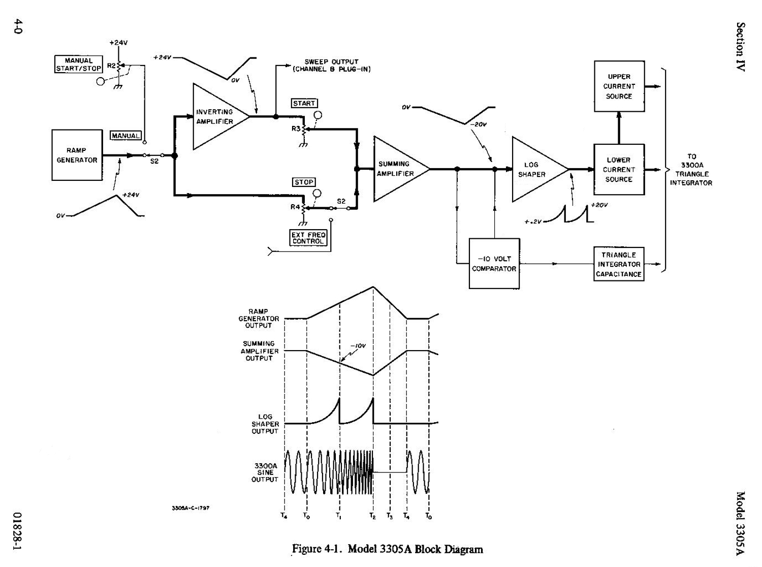 4-6. AUTO.
4-7. The Ramp Generator furnishes a 0 volt to +24 volt linear ramp to the STOP potentiometer and to the Inverting Amplifier. The Inverting Amplifier furnishes a +24 volt to 0 volt linear ramp to the START potentiometer. The voltages from the START and STOP potentiometers coupled to the Summing Amplifier determine the START-STOP range of the sweep.
4-8. When four complete decades are swept upward, the output of the Summing Amplifier is a 0 volt to -20 volt ramp. This ramp is coupled to the Log Shaper an the Ten Volt Comparator. As the ram voltage changes from 0 volts to -10 volts, the Log Shaper output increases exponentially from +0.2 volts to +20 volts, causing the 3300A output to sweep upward two decades.
4-9. When the Summing Amplifier output reaches -10 volts at T1, as shown in Figure 4-l, the Ten Volt Comparator replaces the exact amount of current being taken from the Shaper input. This drops the Shaper output voltage by a factor of 100 from +20 volts to +0.2 volts. At the same time the Triangle Integrator Capacitance is decreased (switched) by a factor of 100.
4-10. The current to the 3300A Triangle Integrator is directly proportional to the Log Shaper output voltage, therefore if at T1 the value of i is decreased by 100 and the value of c is decreased by 100 there is no change in f at T1 as indicated by the basic frequency equation:
f = i / (2cΔe)
where f is the 3300A output frequency, i is the current to the 3300A Triangle Integrator, c is the integration capacitance and Δe is the peak-to-peak voltage of the 3300A Triangle Integrator output.
4-11. After T1 the Log Shaper output voltage again increases exponentially from +0.2 volts to +20 volts as input changes from -10 to -20 volts. This second exponential change of +0.2 to +20 volts continues to sweep the 3300A output an additional two decades higher.
4-12. The two exponential ramps from the Log Shaper are coupled to the Lower Current Source, then to Upper Current Source as shown in Figure 4-1. The Upper and Lower Current Sources furnish a varying current, proportional to the Log Shaper output voltage, to the 3300A Triangle Integrator to produce the proper output frequency.
4-13. By changing the two frequency determining elements at T1 and producing two exponential ramps, the 3305A is able to sweep 4 full decades with improved accuracy and stability.
4-14. At T2 the ramp generator output voltage starts decreasing. During this retrace time, from T2 to T4, the 3300A oscillator is disabled. At T4 the 3300A starts oscillation at the start frequency and continues at this frequency until another sweep starts at T0. This small “waiting time” T4 to T0 permits any transients, introduced at T4 when the blanking is removed, to subside before the start of the next sweep. At time T0 the Ramp Generator starts generating another 0 to +24 volt ramp to repeat the sweep cycle.
4-15. The retrace time (T2 to T4) is controlled by the SWEEP TIME switch. In the 100-10 and 10-1 positions the sweep retrace time is less than 4 seconds. In the l-.1 position, retrace time is less than 30 msec. In the .1-.01 position the retrace time is less than 3 msec. The SWEEP TIME switch and vernier also control the slope of the ramp, therefore controlling the sweep time (T0 to T2).
4-16. TRIGGER.
4-17. In TRIGGER, depressing the TRIG button or applying an external trigger to the TRIG/FREQ CONTROL jack will cause the 3305A to sweep the 3300A one time as described in AUTO mode. After each sweep the 3300A output will wait at the start frequency until another trigger is supplied.
4-18. EXTERNAL FREQUENCY CONTROL.
4-19. In EXT FREQ control the STOP potentiometer is disconnected and the output of the Inverting Amplifier is held at +24 volts. In this mode the sum of the voltage from the START potentiometer and the voltage applied to the TRIG/FREQ CONTROL jack determines the 3300A output frequency by – controlling the Summing Amplifier output. With no voltage applied to the TRIG/FREQ CONTROL jack, the 3300A frequency is that of the START setting. For each +6 volts applied to TRIG/FREQ CONTROL jack, the frequency increases one decade until the upper limit of the four decades is reached. Each -6 volts decreases the frequency one decade until the lower limit of the four decades is reached.
4-20. MANUAL.
4-21 In MANUAL, the MAN. START/MAN. STOP potentiometer replaces the Ramp Generator. The MAN. START/MAN. STOP potentiometer varies the voltage applied to the STOP potentiometer and Inverting Amplifier from 0 to +24 volts. This allows the 3300A frequency to be manually controlled over a four decade range with the MAN. START/MAN. STOP control.
4-22. MAIN FRAME.
4-23. In MAIN FRAME, the 3300A main frame operates independently .of the 3305A plug-in. The theory of operation for the main frame is discussed in 3300A Operating and Service Manual.
4-24. SCHEMATIC THEORY.
4-25. Paragraphs 4-26 through 4-45 refer to AUTO mode except where otherwise specified. Figure 4-1 shows wave form relationships. Refer to Schematic Diagram 1, Figure 7-2.
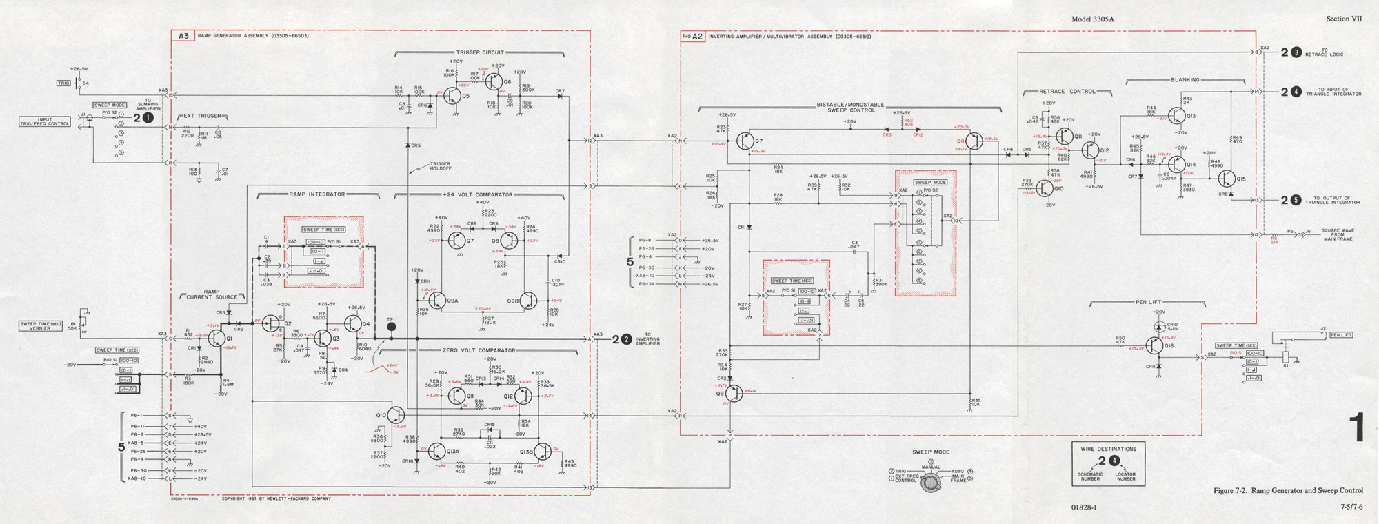
4-26. RAMP GENERATOR ASSEMBLY.
4-27. At To A2Q9 is turned off by the Sweep Control, operating as a monostable multivibrator. A3CR2 is now forward biased and A3CR3 is back biased. Current can now flow through A3Q1 from A2C1 (capacitor used depends on the SWEEP TIME switch position). A linear voltage ramp is integrated from 0 volts to +24 volts measured at A3TP1.
4-28. The slope of the ramp is controlled by the SWEEP TIME switch and vernier. When the ramp reaches +24 volts at T2, A3Q9A turns on. This cuts A3Q8 off; causing a current to flow through A3CRl0, which triggers the monostable Sweep Control. A2Q9 starts furnishing current to discharge the ramp integrator capacitor A2C1. The integrator output voltage then decreases until it reaches 0 volts at T4.
4-29. At T4 the Zero Volt Comparator senses the 0 volt level and turns on A3Q10. The Zero Volt Comparator adjusts the current flowing through A3Q10 to hold the output of the Ramp Integrator at 0 volts until another ramp begins at the next T0.
4-30. INVERTING AMPLIFIER/MULTIVIBRATOR ASSEMBLY.
4-31. The Bistable-Monostable Sweep Control operates as a monostable multivibrator in AUTO and as a bistable in TRIG. In EXT FREQ CONTROL, MANUAL, and MAIN FRAME the bistable is held in one state by A2R32. Refer to Figure 4-2 for a simplified schematic diagram of the Sweep Control.
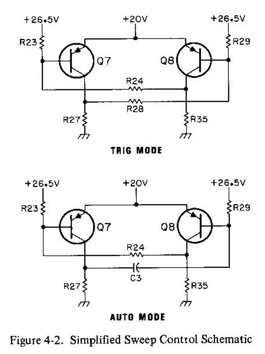
4-32. In TRIG the sweep may be started by depressing the TRIG button or applying a positive external trigger voltage. The trigger voltage is amplified by A3Q5 and A3Q6, and is coupled through A3CR7 to the base of A2Q7. This positive voltage turns off A2Q7, which causes A2Q8 to saturate. The Bistable Sweep Control now causes the Ramp Integrator to start a ramp voltage being generated as explained in Paragraph 4-27.
4-33. At T2 the 24 Volt Comparator causes a current to flow through A2CR10 from the base of A2Q7, and A2Q7 becomes saturated. This applies about + 22 volts to the base of A2Q8, turning it off.
4-34. In AUTO the 24 Volt Comparator turns on A2Q7 at T2, as explained in Paragraph 4-33. As A2Q7 saturates, the positive-going waveform on the collector of A2Q7 is coupled to the base of A2Q8 through A2C3 (and A2C4 and A2C5 at sweep times greater than one second). This prevents A2Q8 from conducting until A2C3 discharges to about l9 volts, at which time A2Q8 once more conducts and starts another sweep.
4-35. The Retrace Control causes the Blanking circuit to blank the output of the 3300A triangle integrator during the retrace time from T2 to T4. At T2 the collector voltage of A2Q8 drops to 0 volts, drawing current through A2R40 and saturating A2Q12. Base current is now supplied through A2R44 to saturate A2Q13. Current is now drawn from the input of the triangle integrator through AZR43. Because of the current flowing in A2R43, the output of the 3300A triangle integrator rises quickly to +20 volts, triggering the +20 volt comparator.
4-36. The +20 volt square wave output of the Comparator is applied to A2CR7. The “and gate” circuit formed by A2CR6 and A2CR7 now reverse-biases the base of A2Q14, turning it off. The voltage on the base of A2Q15 will now be +9 volts. The +20 volt output of the triangle integrator is coupled through A2CR8 to the emitter of A2Q15. A large current now flows through A2Q15 until the triangle integrator output gets down to +10 volts. At this point A2Q15 supplies just enough current to the input of the triangle integrator to hold the integrator output at +10 volts. The output in SINE and TRIANGLE is now 0 volts.
4-37. At T4 the voltage at the collector of A3Q12 rises to -14 volts. A current will now flow through A2R39, saturating A2Q10. The current which now flows through A2R37 and A2R38 causes A2Q11 to saturate and turn off A2Q12. The collector voltage of A2Ql2 will now fall to -21 volts, turning off A2Ql3 and turning on A2Ql4. This allows the 3300A triangle integrator to begin normal operation again.
4-38. At T0 A2Q16 starts conducting, causing the Pen Lift relay A2K1 contacts to close. At T2 A2Q16 is turned off, opening the A2K1 contacts. This offers a recorder pen control at sweep times longer than one second. At sweep times shorter than one second, the SWEEP TIME switch opens the pen lift circuit, so that the relay will not operate.
4-39. Paragraphs 4-40 through 4-45 refer to Schematic Diagram 2, Figure 7-3.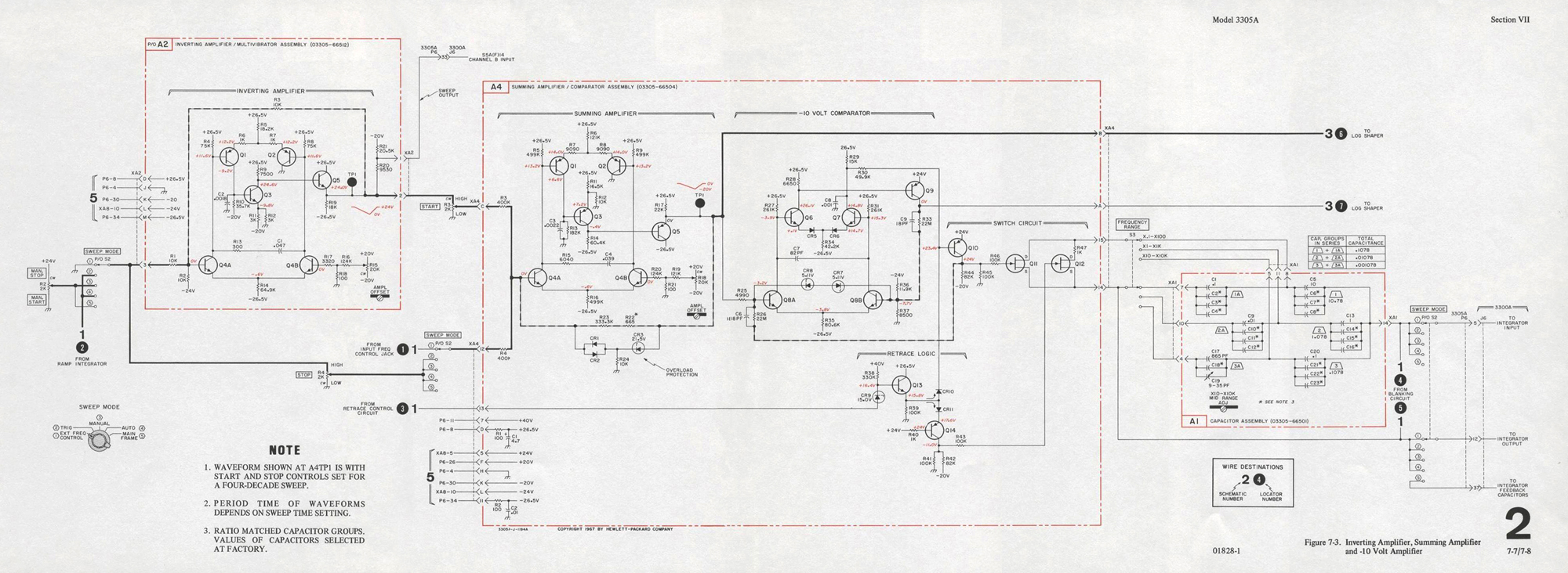 4-40. The +24 volt ramp is applied through the SWEEP MODE switch to both the Inverting Amplifier input and the STOP potentiometer. The Inverting Amplifier has unity gain, as determined by A2R1 and A2R3 (A = R3/R1) . The Inverting Amplifier output is a +24 volt to 0 volt negative-going ramp. This ramp is applied to the START potentiometer».
§§§
Continua nella quarta parte.
Per consultare le altre schede scrivere “ 3305A” su Cerca. Per consultare le schede del generatore di funzioni 3300A scrivere “3300A”.
Foto di Claudio Profumieri, elaborazioni e ricerche di Fabio Panfili.
Per ingrandire le immagini cliccare su di esse col tasto destro del mouse e scegliere tra le opzioni.