
 3300A FUNCION GENERATOR della HEWLETT PACKARD GMBH. Matr. N° G 746-00720. Seconda parte.
Nell’inventario per reparto N° 7 di Elettronica, in data febbraio 1968, al n° D 4236 si legge: “A FUNCTION GENERATOR S. 3300 A – HP” ; e la n° D 4236 si legge: “A AUXILIARY PLUG-IN 3301 – HP”, ma forse si tratta del mod. 3305!
È facile trovare le istruzioni in internet agli indirizzi elencati sotto.
http://bee.mif.pg.gda.pl/ciasteczkowypotwor/HP/3300A.pdf
http://hpmemoryproject.org/wb_pages/wall_b_page_10c.htm
http://www.kennethkuhn.com/students/ee431/mfg_data/hpj_nov_1965.pdf
http://www.hpl.hp.com/hpjournal/pdfs/IssuePDFs/1968-05.pdf
Da questi si deduce che il generatore di funzioni 3300A è stato messo sul mercato nel 1965; mentre il plug-in 3305A è in vendita dal 1968.
Quel che segue è tratto dalle istruzioni della H-P conservate nell’archivio della Sezione Elettronica.
Il testo prosegue dalla prima parte.
§§§ « SECTION III
OPERATING INSTRUCTIONS
3-1. INTRODUCTION.
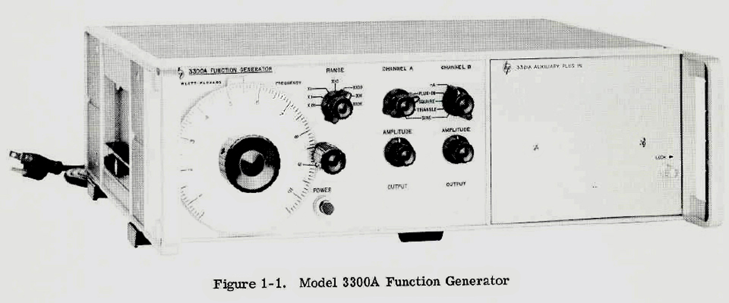
3-2. This section consists of instructions and information necessary for the operation of the -hp- Model
3300A Function Generator.
3-3. CONTROLS AND INDICATORS.
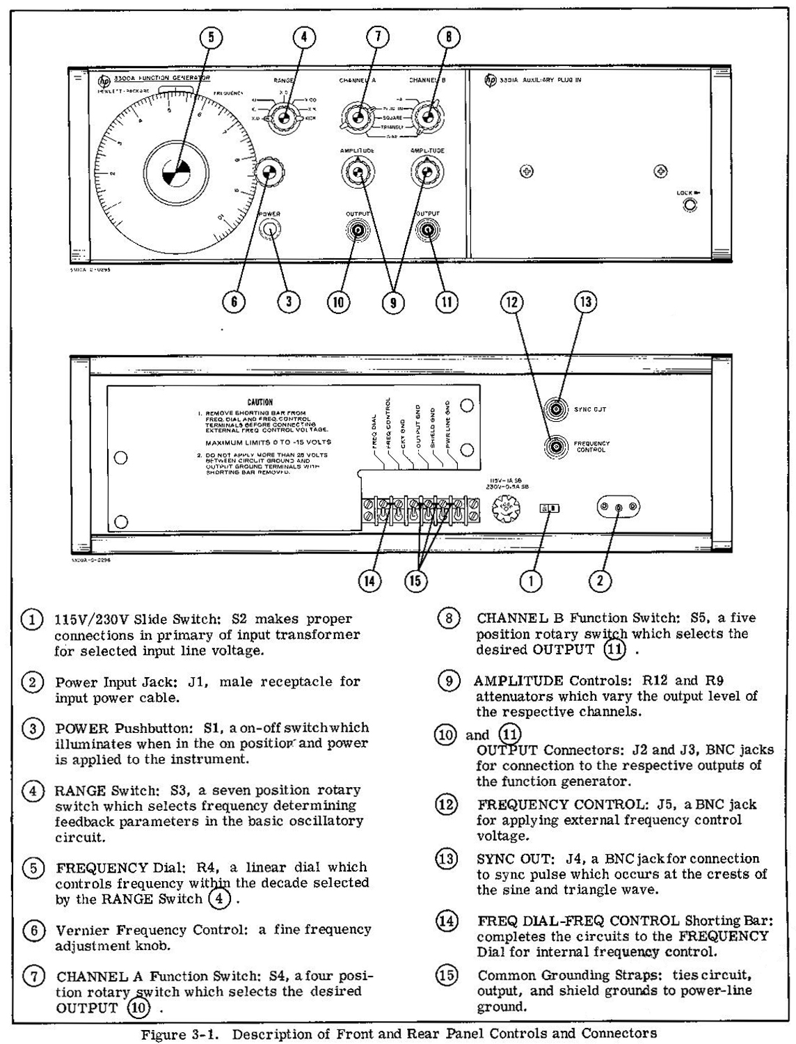
3-4. Each operating control and connector located on the 3300A is identified and described in Figure 3-1.
The description of each component is keyed to an illustration of that component.
3-5. TURN ON PROCEDURE. .
3-6. To turn on the Model 3300A, proceed as follows: (Refer to Figure 3-1).
a. Set 115/230 v slide switch (1) to line voltage to be used, and check for proper value fuse (0.6 amp slow-blow for 115 volt operation, 0.4 amp slow-blow for 230 volt operation).
b. Connect Power Input Jack (2) to the ac line voltage with the power cord furnished with instrument.
c. Depress POWER button (3) ; ensure that light in button illuminates.
3-7. OPERATING INSTRUCTIONS.
-NOTE For small signal applications to obtain optimum signal to noise performance, use an external 20 dB attenuator.
NOTE -0.5 to -10 volts will linearly control the frequency over one decade of range selected. A +0.3 to -10 volts will linearly control the frequency over 50:1 range. Select desired frequency range and set
amplitude of externally applied voltage for desired frequency. All 3300A controls except the FREQUENCY dial are operated in the same manner as in Paragraph 3-8.
3-8. To operate the Model 3300A locally using the FREQUENCY dial, proceed as follows: (See Figure 3 -1.)
a. Select desired frequency by setting RANGE Switch (4) and FREQUENCY Dial (5) .
b. Select desired function by setting CHANNEL A and/or CHANNEL B Function Switch (7) or (8). PLUG-IN position is used for plug-in function(s).
c. Set AMPLITUDE controls for desired output at the OUTPUT connectors (10) or (11).
3-9. To control the frequency of the Model 3300A, externally (remotely) proceed as follows:
a. Remove FREQ DIAL-to-FREQ CONTROL shorting bar (14) .
CAUTION
VOLTAGE APPLIED TO FREQ CONTROL BNC SHOULD BE LIMITED TO A VALUE BETWEEN +0.3 AND -15 VOLTS. VOLTAGES OUTSIDE THIS RANGE WILL DAMAGE THE
INSTRUMENT.
b. Apply a negative dc voltage from -0.5 to (12) Volts to the FREQUENCY CONTROL BNC .
NOTE -0.5 to -10 volts will linearly control the frequency over one decade of range selected. A + 0. 3 to -10 volts will linearly control the frequency over 50:1 range.
c. Select desired frequency range and set amplitude of externally applied voltage for desired frequency.
d. All 3300A controls except the FREQUENCY dial are operated in the same manner as in Paragraph 3-8.
3- 10. To dc offset the output function of the 3300A with either the 3301A or 3302A Plug-In, proceed as follows:
a. Remove CKT GND—to-OUTPUT GND shorting Bar (15).
CAUTION: DO NOT EXCEED 3:25 V DC OFFSET VOLTAGE BETWEEN OUTPUT GROUND AND CIRCUIT GROUND.
b. Connect desired dc offset voltage between CKT GND and the common grounds.
NOTE- If additional offset is required apply dc voltage up to ± 250V between out-put ground and power-line ground.
With dc offset voltage applied between output ground and power-line ground the outside conductor on the OUTPUT BNC connector will be at the potential of the offset voltage».
§§§
Per ragioni di presentazione anticipiamo la Sezione V.
§§§
«SECTION V
MAINTENANCE
5-1. INTRODUCTION.
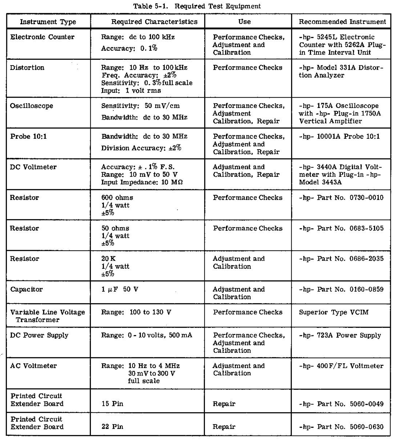 5-2. This section contains information necessary for the proper maintenance of the -hp- Model 3300A Function Generator. The required test equipment is listed in Table 5-1. Test equipment with comparable characteristics can be substituted if recommended equipment is not available.
5-3. PERFORMANCE CHECKS.
5-4. The performance checks are front panel procedures designed to compare the -hp- Model 3300A with its specifications. (See Table 1-1). These checks may be accomplished with either the 3301A Auxiliary Plug-in or Malfunction Isolating Aid Plug (see Figure 5-7) installed in the 3300A. These operations should be completed before any attempt is made to adjust or calibrate the instrument. Allow a
30 minute warm-up period before making performance checks.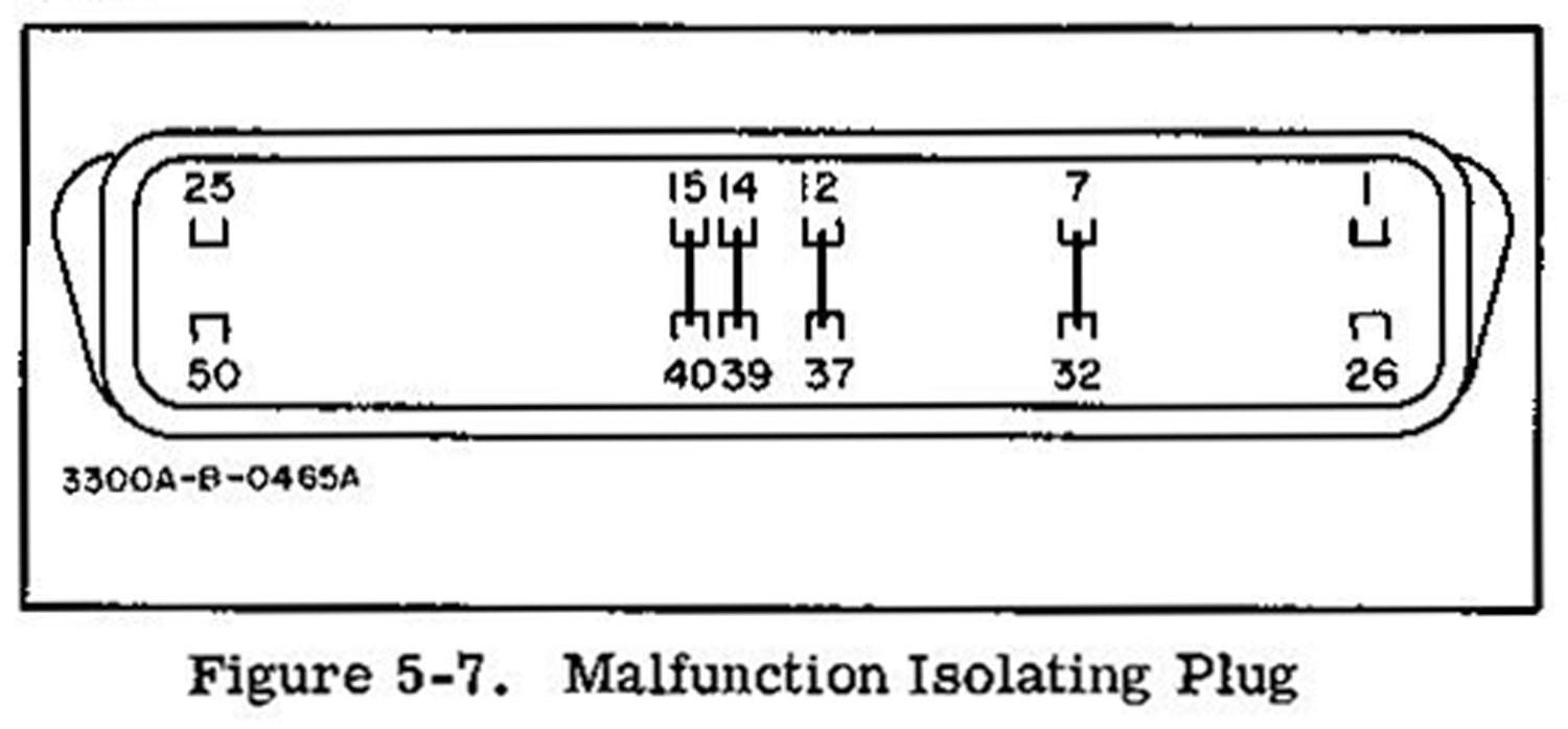 If a performance check indicates that the instrument does not meet specifications refer to the applicable paragraph in the Adjustment and Calibration procedure contained in this Section. (See Table 5-5).
 5-5. DIAL ACCURACY.
a. Test equipment required: Frequency Counter (-hp- Model 5245L).
b. Connect CHANNEL A OUTPUT to the frequency counter and set the 3300A control as follows:
FREQUENCY dial . . . . . . . . . 10
CHANNEL A function switch. . . . SINE
CHANNEL A AMPLITUDE . . . . mid position
c. Check frequency for each position of RANGE switch.
d. Accuracy should be a ±1% of maximum dial setting (one minor division) on X. 01 through
X1K ranges, and = ±2% of maximum dial setting (two minor divisions) on X10K range.
5-6. Since the specification gives % of maximum dial setting (full scale), the accuracy will always be ±1 or 2 minor divisions at any point on the dial.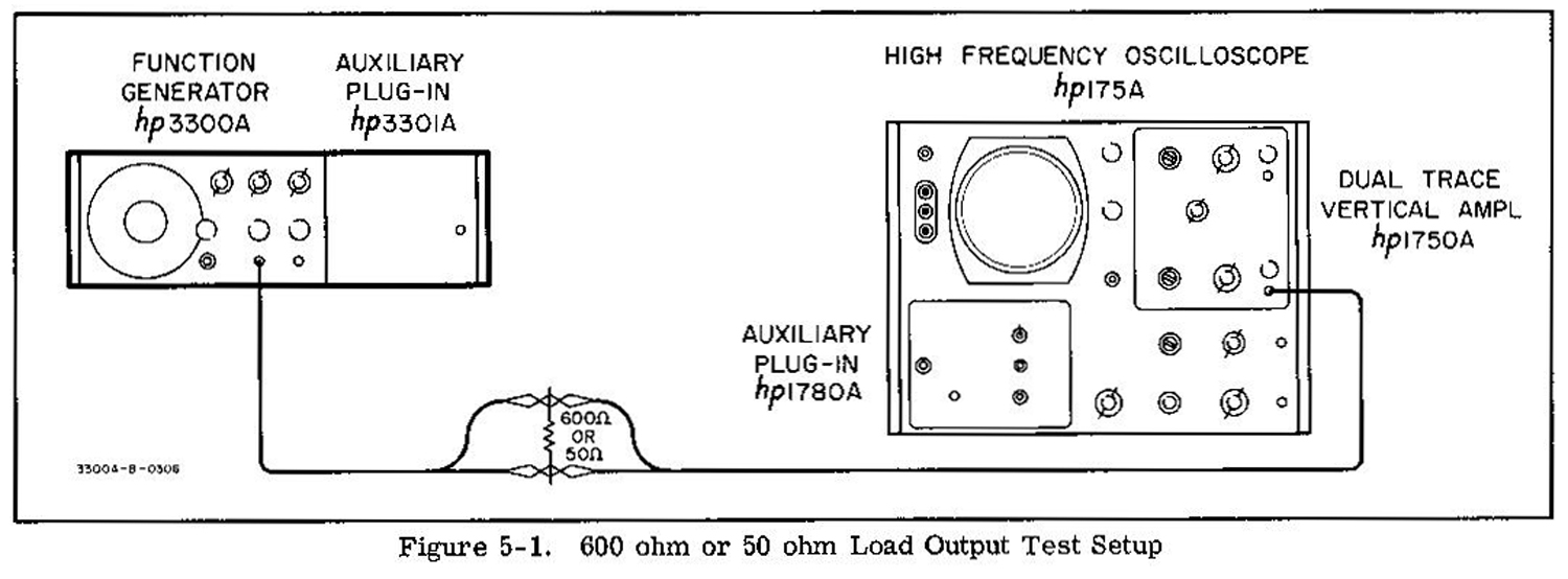
 5-7 . DISTORTION CHECK.
a. Test equipment required: Distortion Analyzer (-hp- Model 331A).
b. Connect the OUTPUT of CHANNEL A to distortion analyzer and set 3300A controls as follows:
FREQUENCY dial . . . . . . . . . 10
RANGE switch . . . . . . . . . . . X1K
CHANNEL A function switch . . . SINE
CHANNEL A AMPLITUDE control . . . . . . . . . . mid position
c. Distortion should be less than 1%.
d. Position the RANGE switch to X10K. Distortion should be less than 3%.
NOTE: The sine function is electronically synthesized from the triangle function. Satisfactory performance of Distortion Check assures symmetry and triangle linearity.
5-8. FREQUENCY RESPONSE .
5-9. Check frequency response over entire range by setting up 10 centimeter peak-to-peak reference on oscilloscopes. 1% equal variation of one-half a minor division, 3% equal variation of one and one-half
minor divisions on oscilloscope.
5-10. MAXIMUM OUTPUT LEVEL, NO LOAD.
a. Test equipment required: Oscilloscope (-hp- Model 175A/1750A).
b. Connect the OUTPUT of CHANNEL A to Oscilloscope and set 3300A controls as follows:
CHANNEL A function switch. . . SQUARE
CHANNEL A AMPLITUDE. . . . Max. CW
c. The peak-to-peak voltage should be > 35 volts over entire frequency range.
5-11. Repeat 5- 10 above with CHANNEL A function switch set to SINE and TRIANGLE. The minimum peak-to-peak voltage remains 35 volts.
5- 12. Repeat 5-10 and 5-11 on CHANNEL B.
5-13. MAXIMUM OUTPUT LEVEL, LOADED.
a. Test equipment required: Oscilloscope (-hp- Model 175A/1750A), 600 ohm, and 50 ohm resistor, see Table 5-1.
b. Connect OUTPUT of CHANNEL A and 600 ohm resistor as shown in Figure 5-1. Set the 3300A controls as follows:
FREQUENCY dial………… 10
RANGE switch………………X100
CHANNEL A AMPLITUDE . . .
control . . . . . . . . . . . ……. Max. CW
CHANNEL A function switch . . SQUARE
c. Peak-to-peak voltage should be > 15 volts.
5-14. Repeat 5-13 on CHANNEL B. Limit remains > 15 volts peak-to-peak.
5-15. Repeat 5-13 and 5- 14 except load the instrument with the 50 ohm resistor. CHANNEL A and CHANNEL B voltage output should be > 2 volts peak-to-peak.
5-16. SQUARE WAVE RESPONSE.
a. Test equipment required: Oscilloscope (-hp- Model 175A/1750A) and 10:1 Probe (-hp- Model 10001A).
b. Connect CHANNEL A OUTPUT without a load to the oscilloscope using 10:1 Probe, and set the 3300A controls as follows:
CHANNEL A function . . . . . . . SQUARE
FREQUENCY dial . . . . . . . . . 10
RANGE switch. . . . . . . . . . X10K
c. Verify: Rise and fall time < 250 nano sec.
Sag < 1%
Overshoot (full output) < 5%
Symmetry error < 1%
Overshoot (full output) < 5%
Symmetry error < 1%
5-18. SYNC OUTPUT.
a. Test equipment required: Oscilloscope (-hp- Model 175A/1750A).
b. Connect SYNC OUTPUT to oscilloscope and set 3300A controls as follows:
FREQUENCY dial . . . . . .10
RANGE switch . . . . . . . . . . . . . . X1K
c. Pulse should be > 10 volts peak-to-peak and < 5 microsecond duration.
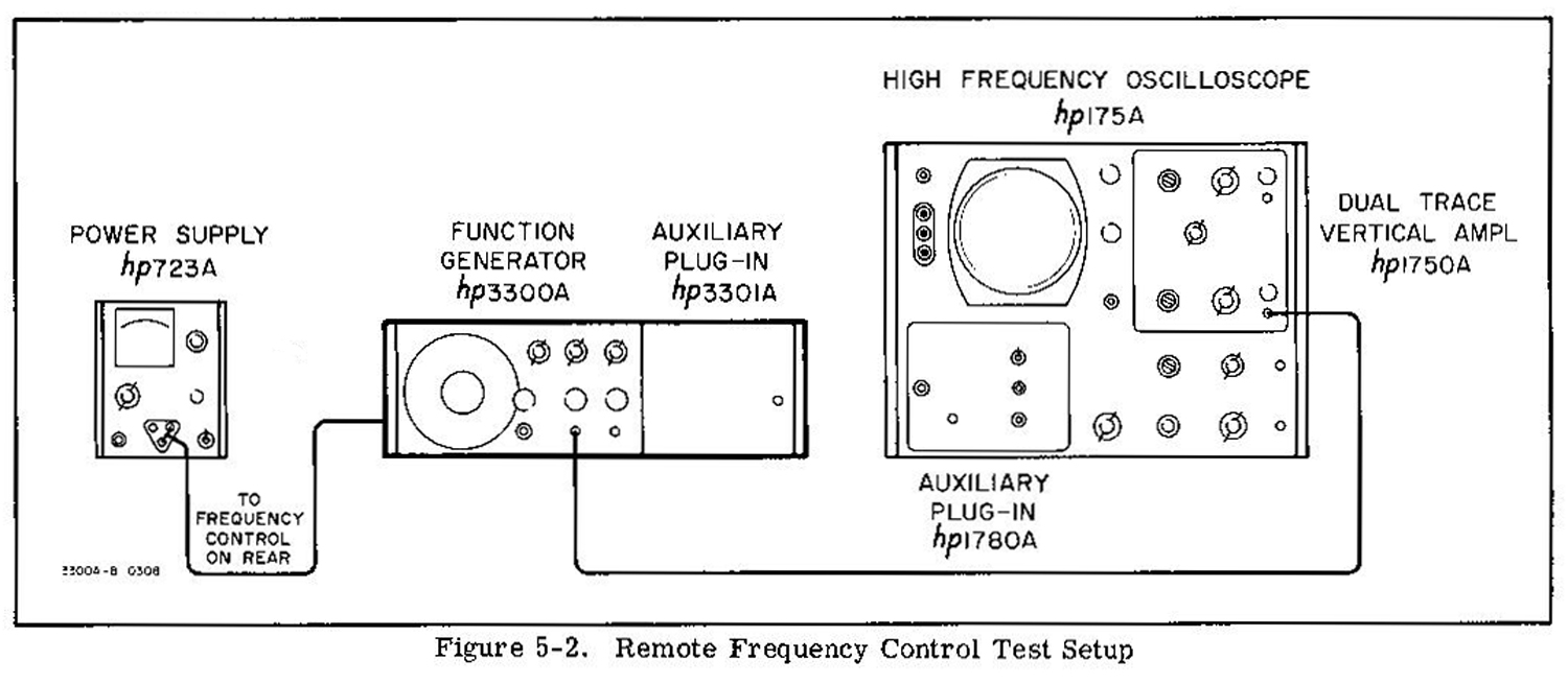
5-19. REMOTE FREQUENCY CONTROL CHECK.
a. Test equipment required: DC Power Supply (-hp- Model 723A) and oscilloscope (-hp- Model 175A)
CAUTION:
VOLTAGE APPLIED TO FREQUENCY CONTROL BNC SHOULD BETWEEN
0 AND NEGATIVE 15 VOLTS. VOLTAGES OUTSIDE THIS RANGE WILL DAMAGE THE
INSTRUMENT.
b. Connect the instruments as shown in Figure 5-2. Remove FREQ. DIAL-to- FREQ. CONTROL
shorting bar.
c. Set 3300A controls as follows:
CHANNELA function switch . . . . SINE
RANGE switch . . . . . . . . . . . X10
CHANNEL A AMPLITUDE . . . . . Max. CW
d. Monitor frequency as power supply is varied from 0 to -10 volts. Frequency should vary over the decade. 10 to 100 cycles.
5-20. CHANNEL B-A CHECK.
a. Test equipment required: Oscilloscope (-hp- Model 175A/1750A).
b. Connect CHANNEL A OUTPUT to one channel of the oscilloscope and CHANNEL B OUTPUT to the other channel of the oscilloscope.
c. Set 3300A controls as follows:
CHANNEL A function switch . . . . . SINE
CHANNEL B function switch. . . . . – A
d. The output of CHANNEL B should be a sine wave, but 180° out of phase with the output of
CHANNEL A.
5-21. ADJUSTMENT AND CALIBRATION.
5-22. COVER REMOVAL.
When it is necessary to repair or adjust the Model 3300A. one or more covers will have to be removed. To remove either the top or bottom cover, remove the two phillips screws and slide the cover to the rear.
5-23. POWER SUPPLY ADJUSTMENTS.
5-24. The adjustment and calibration procedures are designed to adjust and calibrate the -hp- Model 3300A and should be undertaken only if the performance checks indicate the instrument does not meet specifications (see Figure 5-3 for adjustment identification
and location).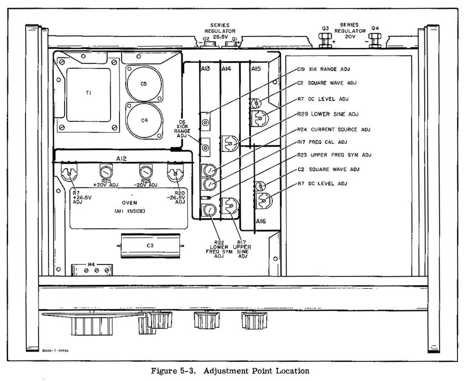
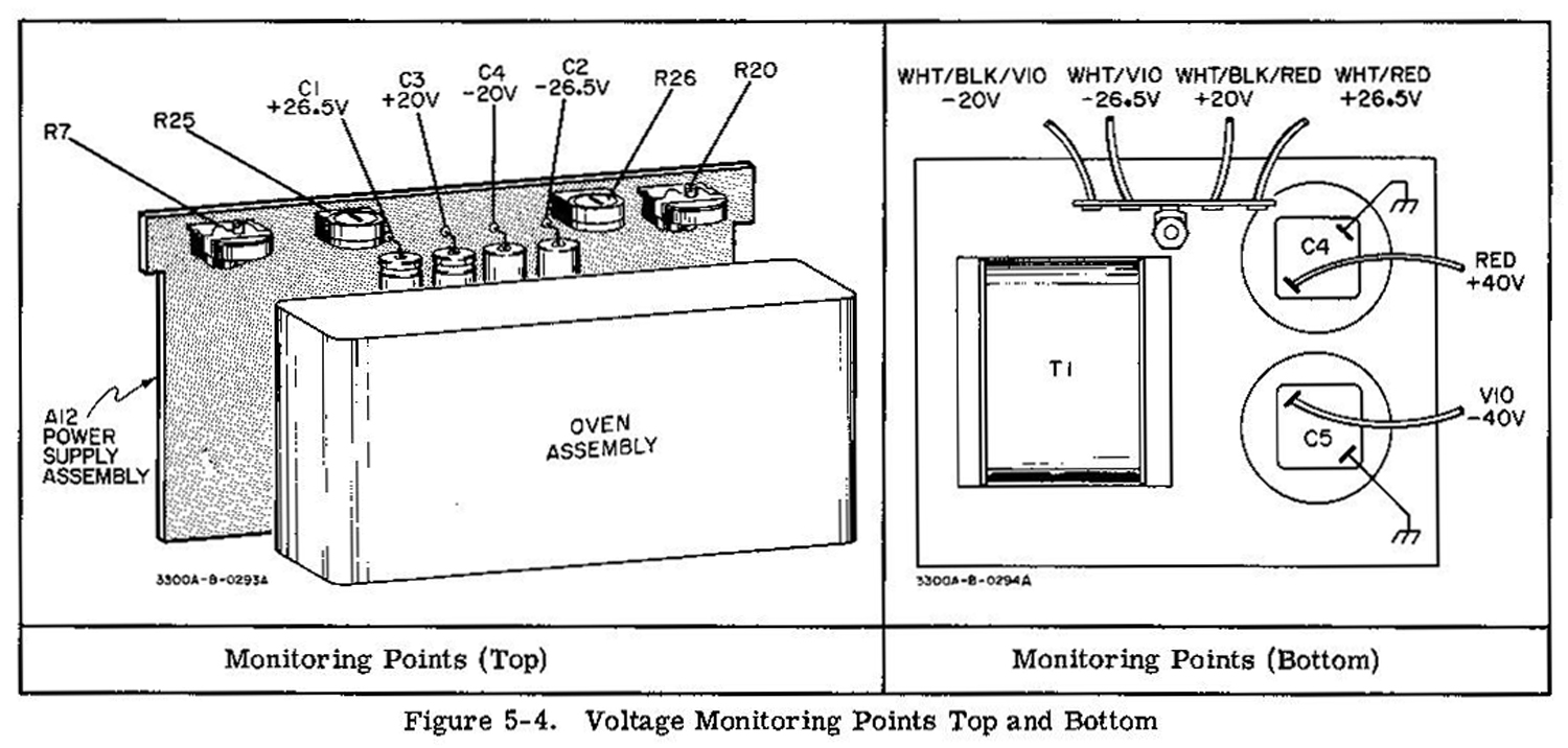
5-25. The measurement points, adjustments and voltage limits are given in Table 5-2. Refer to Figure 5-4 for convenient top and bottom chassis location for monitoring supply voltage. Supplies should be adjusted in the following order: – 26. 5 V, + 26. 5 V. – 20 V. + 20 V. The supplies should be rechecked and, if necessary, readjusted in the same order.
5-26. POWER SUPPLY RIPPLE CHECK.
a. Test equipment required: AC Voltmeter (-hp- Model 400F/FL).
b. With the AC Voltmeter, check the regulated power supplies (±26. 5 V and ±20. 00 V) for ripple.
c. Ripple should be <20 millivolts.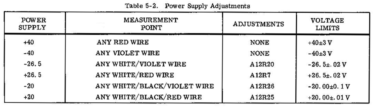 5-27. POWER SUPPLY REGULATION CHECK.
a. Test equipment required: DC Voltmeter (-hp- Model 3440A/3443A) and Variable Line Voltage Transformer.
b. Apply power to the 3300A through the variable line voltage transformer.
c. With the DC Voltmeter. check the regulated power supplies as input voltage to the 3300A is varied from 103 to 127 Vac (207 to 253 Vac). Voltage limits are given in Table 5-2.
5-28. OVEN REGULATION.
a. After 3300A has been on approximately 30 min, connect a DC Voltmeter between circuit ground and collector of Q7 (Q9 on instruments Serial prefixed: 519-, 533-. 609-, 616- and 622-.) Voltage noted should be approximately 20 volts.
NOTE:
This voltage will vary with oven amplifier transistors.
b. Turn 3300A off for approximately 1 minute, then turn it on. Voltage should have decreased to approximately 15 volts. Voltage should then increase and overshoot that noted in step a but in time
damp out to approximately 20 V.
5-29. FREQUENCY SYMMETRY ADJUST.
5-30. Lower Frequency Symmetry Adj. (A13R22).
a. Test equipment required: Electronic Counter (-hp- Model 5245L with 5262A Time Interval
Plug-in), Digital Voltmeter (-hp- Model 3440A/3443A). and DC Power Supply (-hp- Model 723A).
b. Remove FREQ DIAL-to-FREQ CONTROL shorting bar, and connect 3300A CHANNEL
A to counter.
c. Set 3300A controls as follows:
RANGE Switch . . . . . . . . . . X.1
CHANNEL A Function . . . . . . SQUARE
d. Connect DC power supply to FREQUENCY CONTROL BNC and adjust output for +0.3 volts (verify
with digital voltmeter).
e. Measure t1 and adjust A13R22. LOWER FREQ. SYM. . to make t2 = t1. Ref. Figure 5-5.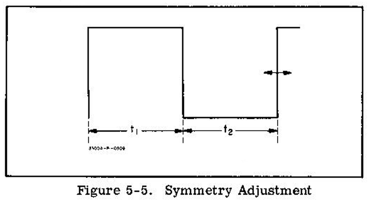 5-31. Upper Frequency Symmetry Adjust. (A13R23).
NOTE:
Lower FREQ. ADJUST must be made before this adjustment. With the same setup as used for 5-30. except select X100 on the RANGE switch, adjust A13-R23 UPPER FREQ. SYM to equalize t1 and t2.
Symmetry error should be < 1%.
% Symmetry error = (t1 – t2 x 100) / (t1 + t2)
5-32 . CURRENT SOURCE ADJUST (A13R24) .
NOTE:
This adjustment interacts with the Frequency Symmetry Adjustments (A13R22 and A13R23):
perform the following adjustment only if the frequency is not within specified accuracy (Table 1-1) on the
X10 or X.1 RANGE.
a. Test equipment required: Frequency Counter (-hp- Model 5245L).
b. Connect CHANNEL A OUTPUT to Frequency Counter, and set 3300A controls as follows:
RANGE switch . . . . . . . . . . . X10
FREQUENCY dial . . . . . . . . . 10
CHANNEL A function . . . . . . . SINE
c. Output frequency should be 100 Hz, ±1 minor division on FREQUENCY dial.
d. Position RANGE switch to X. 1 and measure output frequency 1 Hz, ±1 minor division on FREQUENCY dial.
NOTE:
Repeat Frequency Symmetry Adjust outlined in paragraph 5-29 if A13R24 is adjusted in the following step.
e. If the frequency is not within specifications given in step c or d, adjust A13R24 CURRENT SOURCE ADJ for optimum indication on both X10 and X. 1 RANGE.
5-33 . DIAL ADJUSTMENT.
a. Test equipment required: Frequency Counter (-hp- Model 5245L).
b. Connect CHANNEL A OUTPUT to Frequency Counter, and set 3300A control as follows:
RANGE switch. . . . . . . . . . . . .X100
CHANNEL A function . . . . . . SINE
c. Loosen dial from hub and adjust the frequency of 3300A to exactly 100 cps by rotating the hub. Set the dial to read “1” and tighten the dial to the hub. Recheck the frequency.
5-34. DIAL CALIBRATE .
5-35. FREQUENCY CALIBRATION ADJUST. (A13R17).
a. With same setup as used for 5-33, turn FREQUENCY dial to “10”.
b. Adjust A13R17 FREQ CAL ADJ for output frequency of 1 kHz.
5-36. XIK RANGE ADJUST (A13C19).
a. With same setup as used for 5-33, set RANGE switch to X1K and FREQUENCY dial to “10”.
b. Adjust A13C19 X1K RANGE ADJ for output frequency of 10 kHz.
5-37. X10K RANGE ADJUST (A13C6}.
a. With same setup as used for 5-33 set RANGE switch to X10K and FREQUENCY dial to “10”.
b. Connect CHANNEL A OUTPUT to distortion analyzer and set Model 3300A controls as follows:
FREQUENCY dial . . . . . . . . . . . 1
RANGE switch . . . . . . . . . . . . . X1K
CHANNEL A function . . . . . . . SINE
c. Adjust A14R17. UPPER SINE ADJ and A14R29 LOWER SINE ADJ for minimum distortion.
d. Distortion should be < 1%.
5-38. DlSTORTlON ADJUST (Al4R17 AND A14R29)_.
a. Test equipment required: Distortion Analyzer (-hp- Model 331.)
b. Connect CHANNEL A OUTPUT to distortion analyzer and set Model 3300A controls as follows:
FREQUENCY dial . . . . . . . . . . . 1
RANGE switch. . . . . . . . . . . . . X1K
CHANNEL A function . . . . . . . SINE
c. Adjust A14R17. UPPER SINE ADJ and A14R29 LOWER SINE ADJ for minimum distortion.
d. Distortion should be <1%.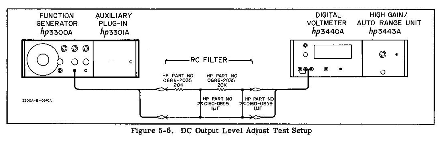 5-39. DC OUTPUT LEVEL ADJUST (A15R7 AND A16R7)
a. Test equipment required: DC Voltmeter (-hp- Model 3440A) and RC Filter see Figure 5-6.
b. Connect CHANNEL A OUTPUT to DC Volt- meter through a filter as shown in Figure 5-6.
c. Set 3300A controls as follows:
RANGE switch . . . . . . . . . . . . X100
FREQUENCY dial . . . . . . . . . 10
CHANNEL A Function . . . . . Vary
CHANNEL A AMPLITUDE. . . . Max. CW
d. Check dc output level on all three functions. Adjust A15R7 DC LEVEL ADJ for minimum voltage on all functions. DC levels should be ±200 mV.
NOTE:
Compromise the adjustment of A15R7 so that all functions are as close to zero volts as possible.
5-40. Repeat 5-39 on CHANNEL B. and adjust A16R7 DC LEVEL ADJ.
5-41. SQUAREWAVE ADJUST 5C2 AND A16C2).
a. Test equipment required: Oscilloscope (-hp- Model 175A) and 10:1 Probe. (-hp- Model 10001A).
b. Connect the CHANNEL A OUTPUT to theoscilloscope using the 10:1 Probe.
c. Set 3300A controls as follows:
CHANNEL A function . . . . . . . . SQUARE
FREQUENCY dial . . . . . . . . . . 10
RANGE switch. . . . . . . . . . . . X10K
d. Adjust A15C2 SQUARE WAVE ADJ for minimum rise time with less than 5% overshoot on the square wave. Rise time should be < 250 nsec .
5-42. Repeat 5-41 on CHANNEL B, and adjust A16C2 SQUARE WAVE ADJ.
5-43. REPAIR PROCEDURES.
5-44. SERVICING ETCHED CIRCUIT BOARDS.
5-45. The Model 3300A has six etched circuit boards. Use caution when removing them to avoid damaging mounted components. The -hp- Part No. for the assembly is marked on the circuit board to identify it and on the appropriate schematic. Refer to Section VII for replacement -hp- Part No. The etched circuit boards are of the plated-through type. The electrical connection between the two sides of the board is made by a layer of metal plated-through the component hole. When working on these boards, observe the following rules:
a. Use a low-heat (25 to 30 watts) small-tip soldering iron, and a small diameter rosin core solder.
b. Remove circuit components by placing the soldering iron on the component lead on either side of the board, and pulling up on the lead. If a component is obviously damaged, clip leads off as close to the
component as possible and then remove leads with a soldering iron.
CAUTION:
EXCESSIVE HEAT CAN CAUSE THE CIRCUIT AND BOARD TO SEPARATE. OR CAUSE DAMAGE TO THE COMPONENTS.
c. Clean component lead hole with the iron and inserting a wooden
toothpick. Remove the toothpick after the solder has cooled and insert the new component lead.
d. Shape the new components leads and insert them in lead holes. Reheat with soldering iron and add a small amount of new solder as required to insure a good electrical connection.
e. Clean excessive flux from the connection and adjoining area.
CAUTION:
TO AVOID SURFACE CONTAMINATION OF THE PRINTED CIRCUIT, CLEAN WITH A WEAK SOLUTION OF WARM WATER AND MILD DETERGENT AFTER REPAIR. RINSE THOROUGHLY WITH CLEAN WATER AND ALLOW IT TO DRY COMPLETELY BEFORE OPERATING. DO NOT USE ALCOHOL OR ANY OTHER CLEANING SOLUTION EXCEPT DETERGENT AND WATER. DO NOT APPLY ANY COMMERCIAL MOISTURE SEALING SPRAY
TO THE BOARDS. APPLICATION OF THESE AGENTS WILL CAUSE LEAKAGE PATHS AND SUBSEQUENTLY, DETERIORATION TO THE OPERATION OF THE INSTRUMENT.
f. Wear clean, lint free cotton or rubber gloves when handling the circuit boards. Avoid touching the board or components with bare, fingers as skin oils can cause contamination and leakage paths.
5-46. SERVICING ROTARY SWITCHES.
5-47. The 3300A has three rotary type switches; RANGE. CHANNEL A, and CHANNEL B. When working on these switches, observe the following rules:
a. Use a low-heat (25 to 50 watts) small tip soldering iron, and a small diameter rosin core solder.
b. When replacing components, attempt to dress them as nearly to their original alignment as possible.
c. Clean excessive flux from the connection and adjoining area.
5-48. REPLACEMENT OF FACTORY SELECTED
COMPONENTS.
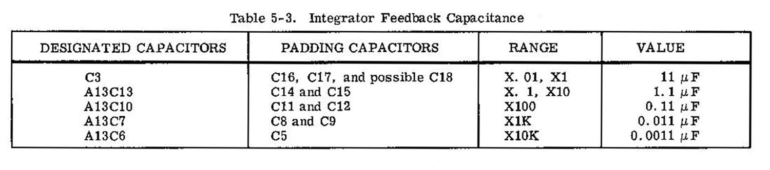
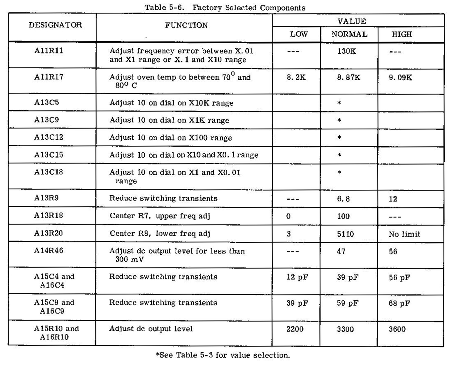
5-49. Replacement of factory selected components are identified in Table 5-3 and 5-6. Should it become necessary to replace any of the capacitors in the feedback circuit of the Triangle Integrator. the
replacement capacitor (a good quality mylar film type) must be selected so that the approximate parallel capacitance is as indicated in Table 5-3. If after capacitor replacement, the resultant frequency is not correct, the necessary capacitor change can be determined by the following formula:
C correction = C feedback / [( Freq- desired Freq x 100)/desired Freq]
Example: X1K range inaccurate Freq of 9.8 KHz ( Range X1K dial 10)
C correction = [ 0.011 μF / (9.8 K – 10K) x 100/ 10K] = -0.01 μF / 8 = .00137 μF
5-50. TROUBLESHOOTING PROCEDURE.
5-51. This section contains procedures designed to assist in the isolation of a malfunction. These procedures are based on a systematic analysis of the instrument in an effort to localize the problem.
These operations should be undertaken only after it has been established that the difficulty cannot be eliminated by the adjustment and calibration procedures outlined in Paragraph 5-21.
5- 52. Conduct a visual check of the 3300A for possible burned or loose components, loose connections, or any other obvious condition which might be a source of trouble. An investigation should also be made to ensure that the trouble is not a result of conditions external to the 3300A.
5-53. The checks outlined in this section are not designed to measure all circuit parameters, rather only to localize the malfunction. Therefore. it is highly probable that additional checks and measurements will be required to completely isolate the faulty component.
Amplifier gain may also vary slightly between instruments; therefore, it is not necessary to precisely duplicate waveforms or voltages described.
5-54. MALFUNCTION ISOLATION PLUG.
5- 55. A malfunction isolating tool can be fabricated for isolating a malfunction to the 3300A or the plug-in unit.
5-56. PRECAUTIONS.
5-57. In the event the -20 volt supply is inoperative, the oven heater should be disabled while troubleshooting.
A point to disable the oven is to disconnect the smaller diameter red wire (26 gage) from XA12 Pin 1. The larger diameter red wire (22 gage) should be left connected to XA12 Pin 1. When the – 20 volt power supply is left out, the oven remains in full heat condition. Thermal fuse A11F1 will melt and open if this heat condition exists for any extended period.
5-58. When troubleshooting Power Supply Assembly, remove the Output Amplifier Assemblies A15 and A16.
5-59. TROUBLESHOOTING TREE.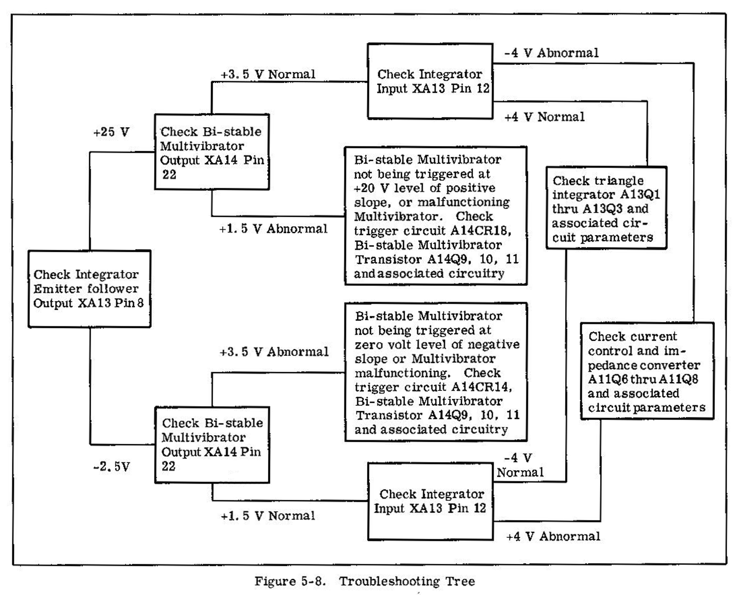 5-60. In the event of a malfunction which causes the oscillatory system to cease functioning; the output of the triangle integrator emitter follower would most likely stabilize at either one voltages as indicated in Figure 5-8. Approximately +25 volts in the upper limit of the positive slope, and –2,5 volts in the lower limit of the negative slope out of the integrator circuit.
The condition of the other major circuits in the basic oscillating loop, the Voltage Comparator Bi-stable Multivibrator and current source, can, in most instances, be used to isolate the malfunction to a given circuit as outlined in Figure 5-8. The term normal, as applied to the results obtained at the different points tested, refers to the output at that point which would reverse the slope at the output of the triangle integrator and sustain oscillation. Abnormal refers to that output which would produce the same slope and prevent oscillation.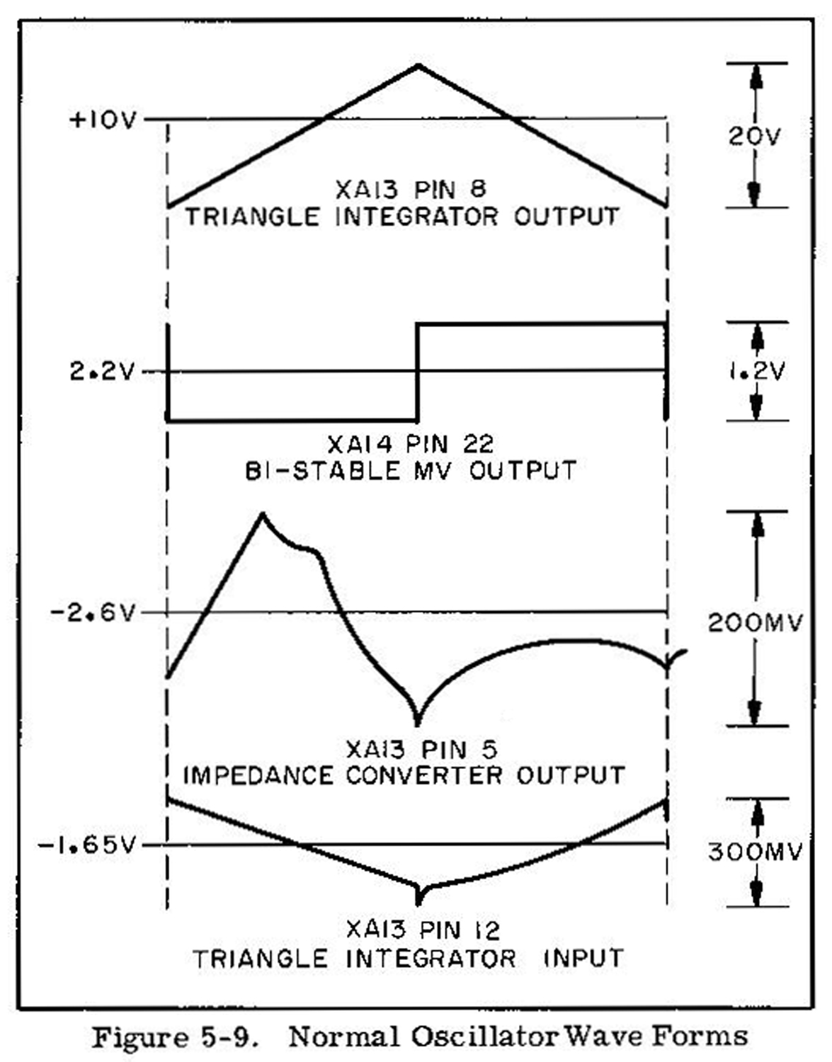 5-61. Figure 5-9 contains the normal voltages and waveforms which should be present at the points
indicated. Voltage levels are approximate and may vary from instrument to instrument due to differences in transistors.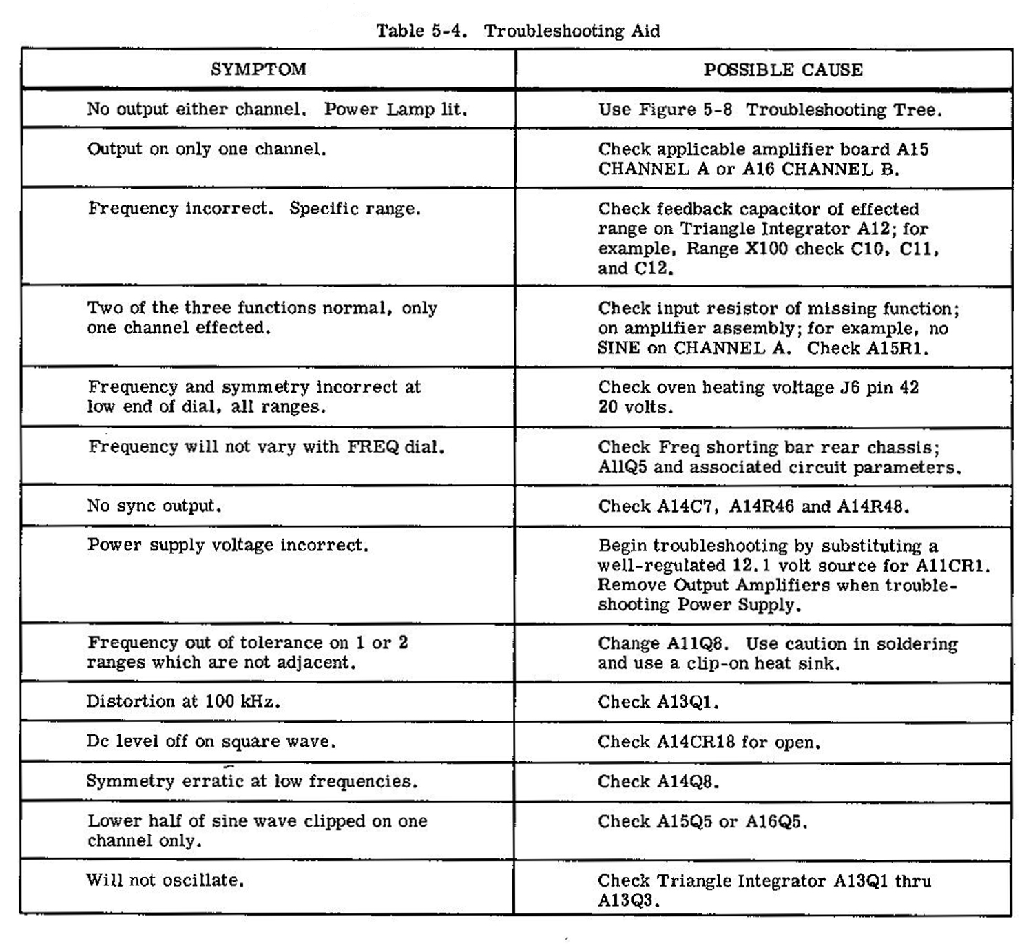
 5-62 . TROUBLE SHOOTING TABLES.
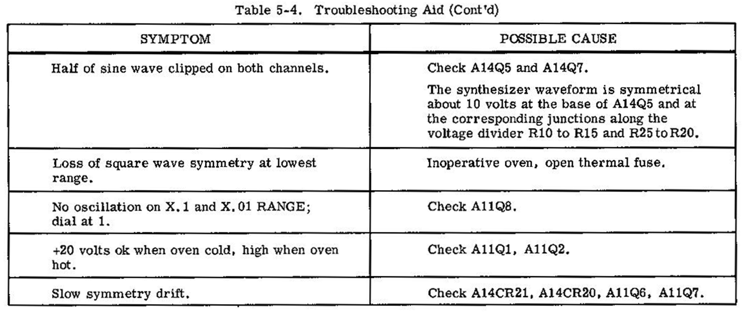
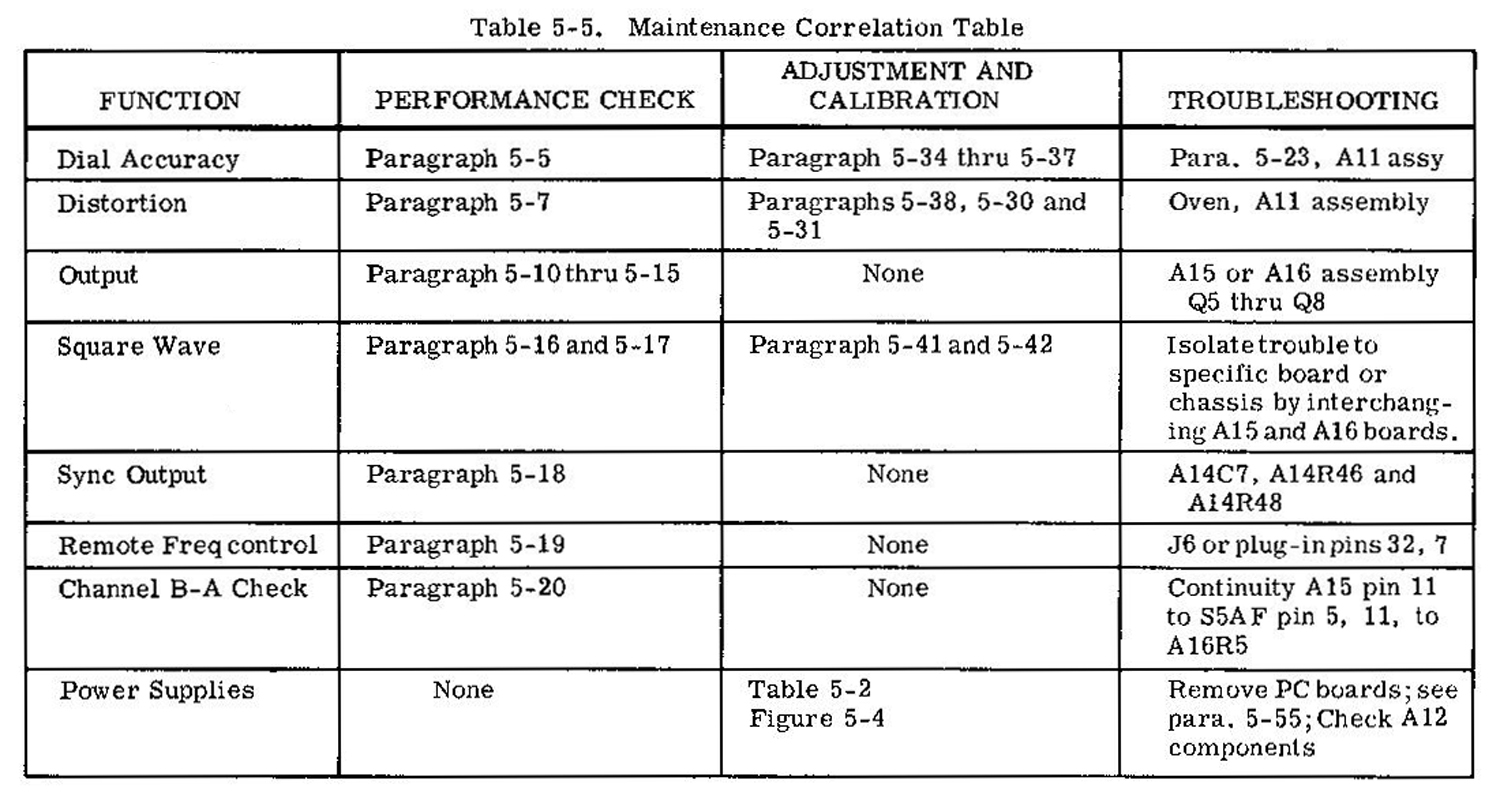
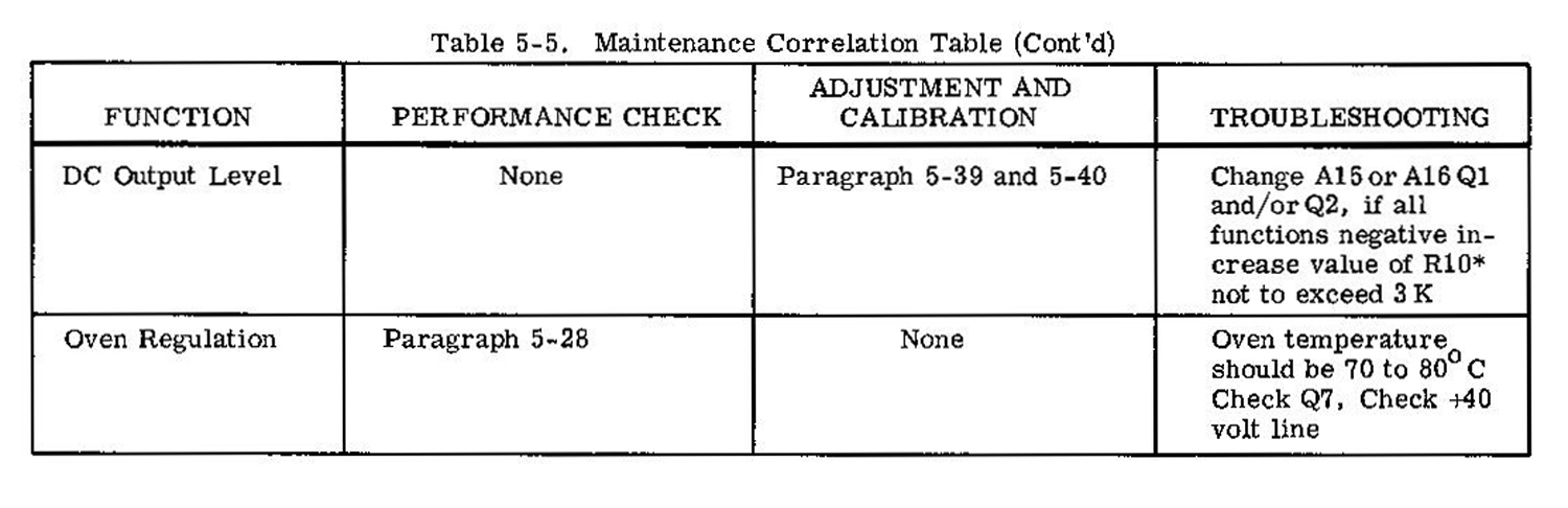
5-63. Table 5-4 gives additional information to assist in the isolation of a malfunction. Symptoms and possible causes are listed. Table 5-5, Maintenance Correlation Table, lists various 3300A functions and gives the corresponding performance checks and adjustments».
§§§
Per consultare le altre due parti scrivere “3300A” su Cerca. Per consultare le schede dello Sweep Plug-In 3305A scrivere “3305A”.
Foto di Claudio Profumieri, elaborazioni e ricerche di Fabio Panfili.
Per ingrandire le immagini cliccare su di esse col tasto destro del mouse e scegliere tra le opzioni.