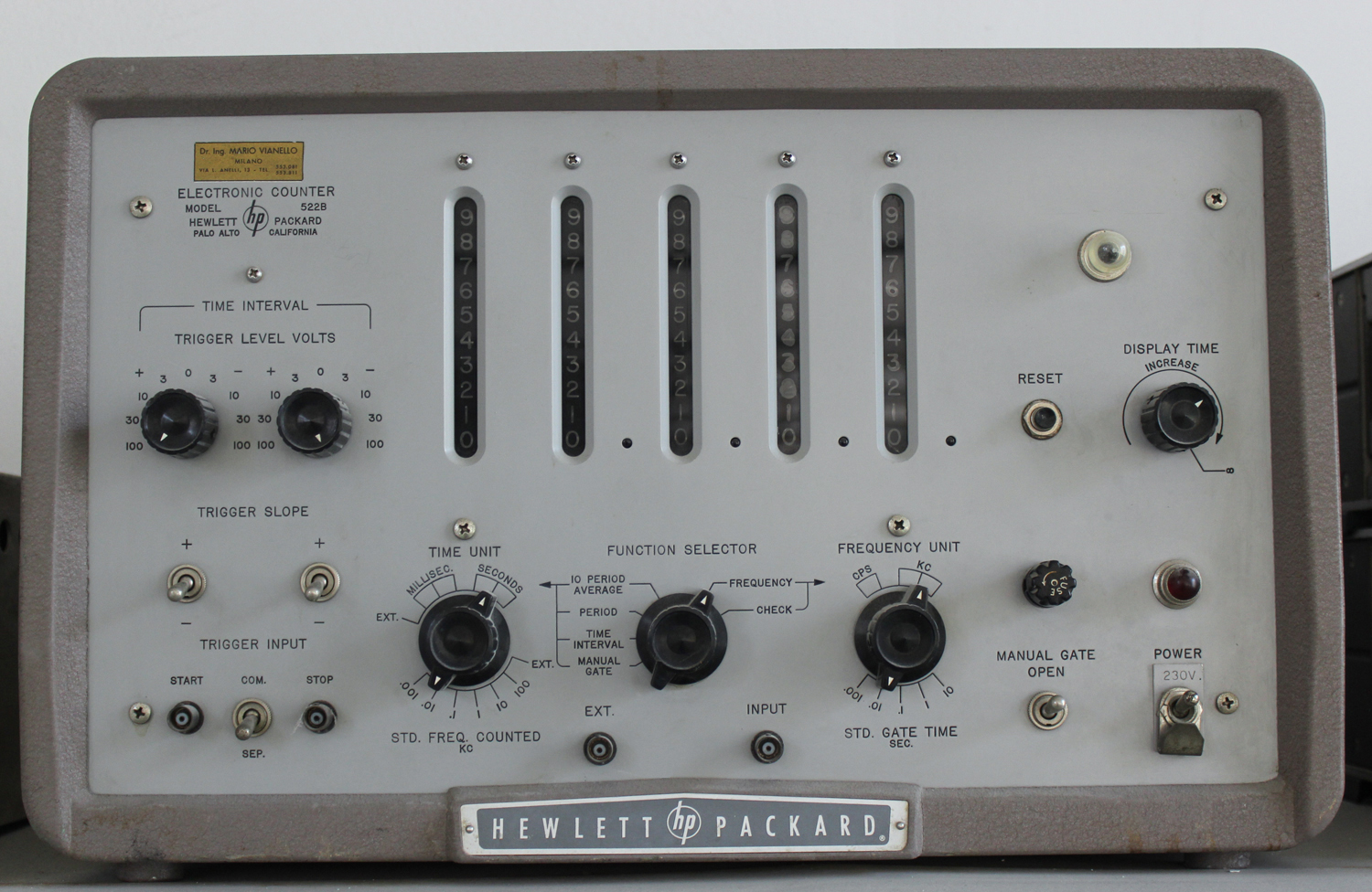
 Electronic Counter Hewlett-Packard Model 522B Serial 2733, Palo Alto California. Importato da: Dott. Ing. Mario Vianello – Milano. Seconda parte.
Nell’inventario D del 1956, in data 7 giugno 1960, al n° 1800 si legge: “Fondazione Carlo e Giuseppe Piaggio – Genova. Contatore elettronico HP mod. 522. Destinazione Radiotecnica”.
All’indirizzo:
https://www.hpl.hp.com/hpjournal/pdfs/IssuePDFs/1952-11.pdf
si può trovare l’Hewlett-Packard Journal Vol. 4 No. 3 del novembre 1952. Il cui titolo è: “A New 100 KC Counter for Use in Electronics and Industry”.
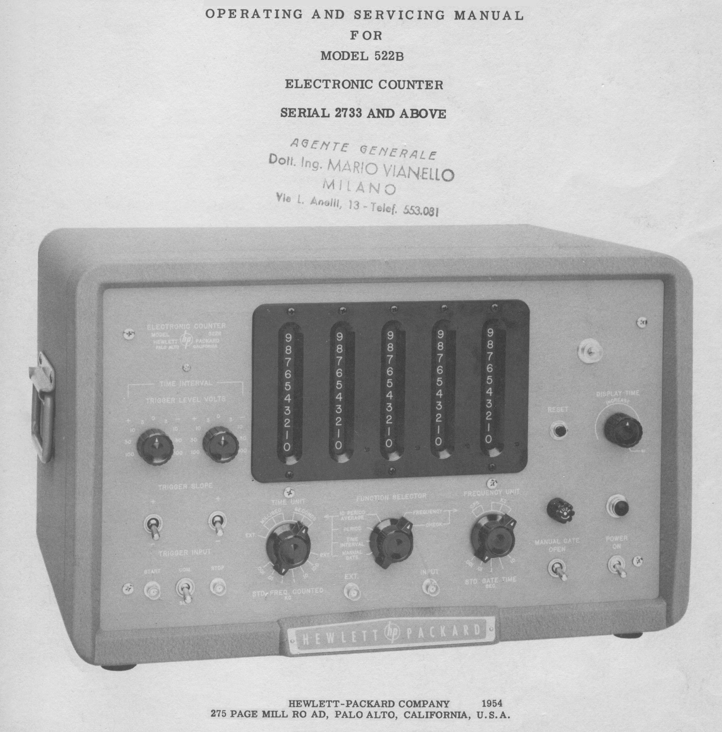
Noi abbiamo preferito riportare una parte del manuale di istruzioni poiché le figure, opportunamente elaborate, sono meglio definite.
Abbiamo diviso il testo in due parti a causa della sua lunghezza e del numero di foto e figure.
Abbiamo deciso inoltre di omettere il capitolo “Maintenance”, ma ne abbiamo riportato le figure.
Il testo prosegue dalla prima parte.
§§§
«2-4 APPLICATIONS
Frequency Measurements
Measurement of frequency is a basic function in counters. Such measurements as oscillator calibration, oscillator drift with time, or drift with line voltage may be made. Frequency response characteristics of tuned circuits, band pass filters, etc. , can be plotted. Some specific frequency measurement applications are described below.
Repetition Rate of Pulses
The repetition rate of pulses is merely counting the pulses for a. standard time. The input of the counter is direct couple d and adjusted to trigger at zero volts. Since a pulse is essentially all positive or all negative from a reference voltage, it may be necessary to introduce some dc bias to enable the pulse to cross the zero axis. With this in mind repetition rates can be measured in the same manner as any other frequency.
Tachometry
There are a number of transducers available for tachometry measurements. The hp Mode1 5063 is 9, photoelectric tachometer head and the hp Model 508A is a 60 tooth magnetic tachometer. The Model 508A is mechanically connected to the shaft being measured and produces 60 output pulses per revolution. An indication of rpm is given directly when the output frequency of the tachometer is measured. With a 1 second gate time, an accuracy of ± 1 rpm is obtained. Using a 10 second gate time ± 1/10 rpm accuracy may be obtained. The Model 506B photoelectric tachometer head is designed for use where mechanical linkage is impractical. The light source and phototube assembly should be adjusted so that the light reflected from the rotating member will enter the phototube. The number of pulses or counts per revolution will depend upon the design of the rotating member. Alternate black and reflecting strips may be placed on the rotating shaft or disc and the speed will be:
speed (RPM) = ( Counter indication × 60) / ( Number of reflecting strips × Gate time in sec.)
Pressure Measurements
The vibrating wire type transducer is a pressure-sensitive element with an associated feedback amplifier. Its output is a frequency which is determined by the pressure exerted on the vibrating wire cell and has a resolution of about .02 percent. The output of the feedback amplifier is connected to the counter to read frequency. Such transducers can be used in remote locations. Since the indication is a single frequency, no alteration of information can be caused by transmission. Similar units can also be obtained for indicating temperature.
Extended Gate Time
It is sometimes desirable to measure a signal for a longer time than provided by the counter in order to obtain an average of fluctuating signal or to obtain greater accuracy. This may be done on either frequency or period measurement. The MANUAL GATE switch, when OPEN, prevents the timing pulses from closing the gate. If on frequency measurement a five-second gate time is desired, the MANUAL GATE switch should be closed some time between the 4th and 5th second after counting has begun. Then at exactly 5 seconds time the next timing pulse will close the gate.
Then:
Freq. in cps = [total number of counts] / [gate time (sec.) ]
Since with a longer gate time the total count increases, the ± 1 count error decreases. Thus for a 5-sec. gate, for example, the ± 1 count error is 1/5 that of a 1-sec. gate. The number of periods being measured can also be extended by using the MANUAL GATE switch in a similar manner.
Frequency Ratio
The period of a wave generally is measured in terms of time. If the TIME UNIT switch is turned to EXT. the period may be measured in terms of another frequency, and the displayed count will be the ratio between the two frequencies. If the lower of the two frequencies is connected to INPUT, the higher of the two connected to EXT., and the FUNCTION SELECTOR set at PERIOD, frequency ratios from 1:1 to 100,000:1 may be read. With FUNCTION SELECTOR set at 10 PERIOD AVERAGE, ratios may be read from .1:1 up to 10,000:1. If it is desired to measure larger ratios, a mechanical register may be connected to the COUNTER OUTPUT to extend the range.
Time Interval Measurements
Many time interval measurements are possible with the Model 522B, the basic requirement being an electrical impulse at the beginning and end of the desired time interval. This impulse may be generated by any one of a number of specialized transducers, switches, phototubes, etc.
The Hewlett-Packard Journal, Vol. 5, No. 1-2, is devoted to time interval measurements with the Model 522B. It discusses a marker generator that may be of value when making time interval measurements. When making time interval measurements on a complicated waveform, the marker will be helpful in setting the trigger level controls correctly. Contact the Hewlett-Packard Company if you desire any further details on time interval measurements or the marker generator.
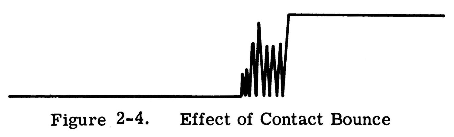
CAUTION
When mechanical contacts of any kind (relay, switches, etc.) are used to generate impulses for time interval measurements, precautions must be taken. Mechanical contacts are subject to contact bounce which produces a very irregular impulse as indicated in Figure 2-4. This type of pulse will not trigger the counter at the desired time and under these conditions it is impossible to make accurate or consistent measurements. When mechanical contacts are used to trigger the counter, the impulse from these contacts should be viewed on a wide band oscilloscope. Any irregularities that are present may then be taken into account.
 Phototubes
Photoelectric transducers are used where it is impossible or impractical to use mechanical connections for the desired measurement. A 90-volt phototube polarizing voltage is available at the rear of the instrument. The output of the phototube may be connected to either the START or STOP input of the counter through a coupling capacitor. Since these are direct-coupled inputs, it is desirable to include a blocking capacitor between the phototube and the instrument input.
Phase Shift Measurement
The phase difference between two waveforms having the same frequency may be measured in terms of time or electrical degrees. Direct measurements in degrees require using an external source, having a frequency that is 360 times that of the waveform being measured, as the TIME UNIT. (This voltage is applied at the EXT. input connector.) To make phase measurements the instrument is set up as follows:
1.FUNCTION SELECTOR on TIME INTERVAL.
2.TRIGGER INPUT on SEP.
3.MANUAL GATE closed.
Connect the two waveforms to the STOP and START TRIGGER INPUTS, set both TRIGGER LEVEL VOLTS controls at approximately zero both TRIGGER SLOPE switches positive. Note the count. Switch both TRIGGER SLOPE switches to negative and note the count. If these two counts are not equal, adjust the START TRIGGER LEVEL VOLTS control until equal counts are obtained with both TRIGGER SLOPE switches positive and both negative.
Phase Shift (degrees) = 360 × F × {[count (milliseconds)] / 1000}
Where F is the frequency of the waveform being measured. This is the number of degrees the START waveform leads the STOP waveform. If an external TIMEUNIT is used that is 360 times the frequency of the measured waveform, the count will be the number of degrees the START waveform leads the STOP waveform and no calculations will be required. Maximum accuracy is obtained when the instrument is triggered at or near the zero axis crossing of the sine wave. The two counts will be equal when the START and STOP channels are triggered the same number of electrical degrees from the zero axis crossing of each waveform. This measurement is explained as follows: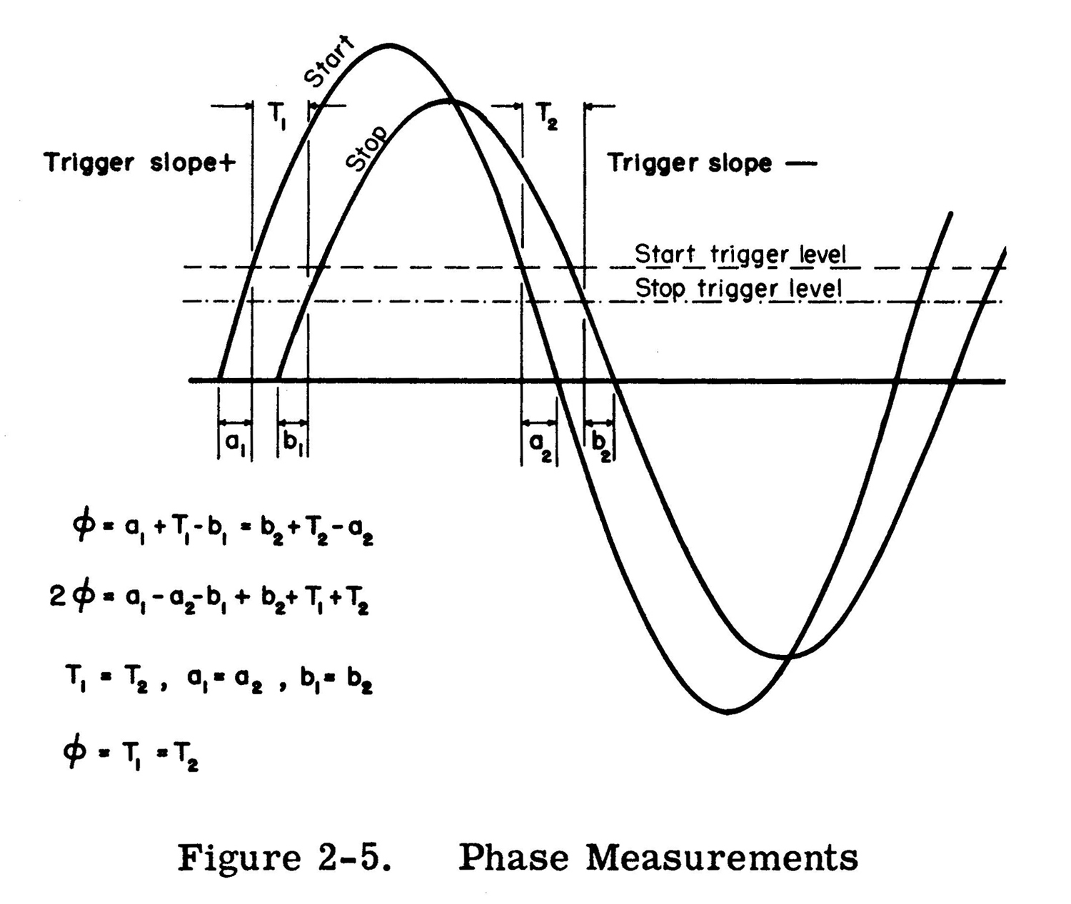 In the illustration T1 = T2 since we have specified equal counts with both TRIGGER SLOPE switches + and both -. Because of the symmetry of the waveforms a1 = a2 and b1 = b2.
SECTION Ill
THEORY 0F OPERATION
 3-1 INTRODUCTION
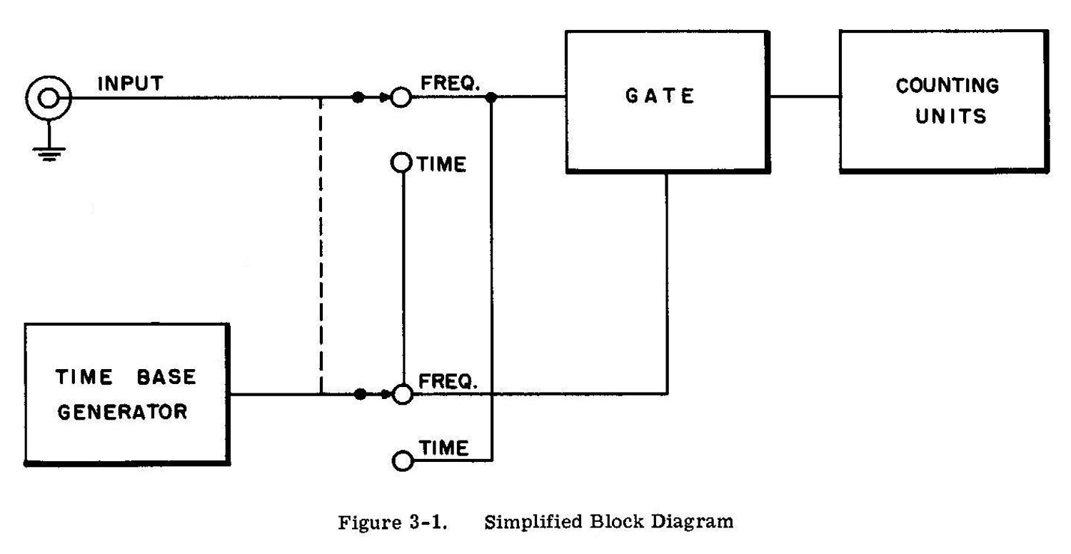
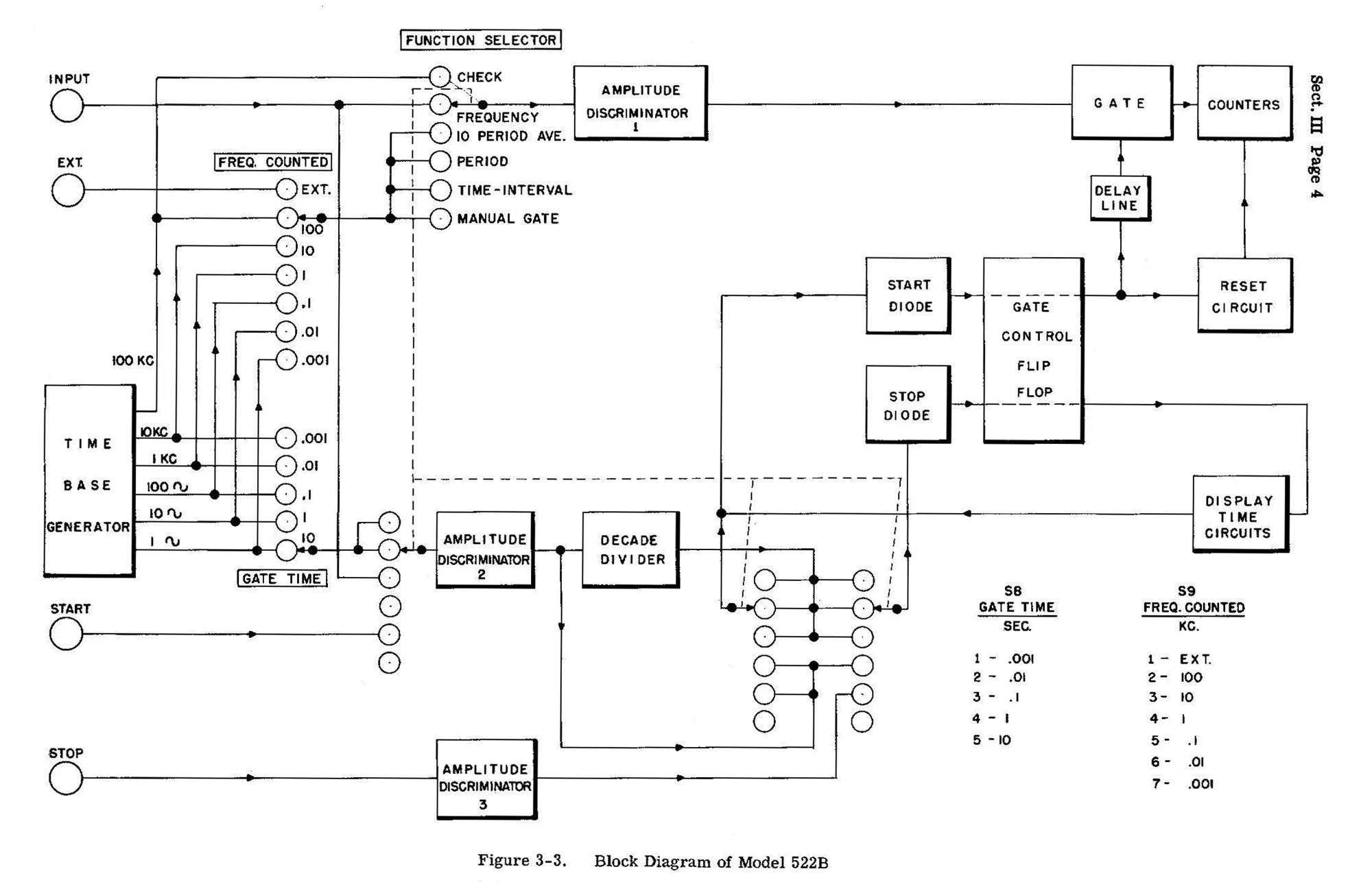
This Section describes the electrical operation of the circuits of the 522B Electronic Counter. First the overall operation of the instrument is explained with reference to the block diagrams in Figure 3-1 and 3-3, then the operation of important circuits is described in detail. The material in this section is as follows:
3-2 Overall Circuit Operation
3-3 Time Base Section
3-4 Phantastron Frequency Dividers
3-5 Decade Frequency Divider
3-6 Amplitude Discriminator
3-7 Signal Gate Section
3-8 Signal Gate
3-9 Gate Control Binary
3-10 Display Time Circuit
3-11 Reset Circuit
3-12 Time Interval Input Circuit
3-13 Power Supply
3-2 OVERALL CIRCUIT OPERATION
The 522B Electronic Counter consists of the basic circuit sections shown in the block diagram in Figure 3-3. A signal applied to the 522B INPUT connector is fed through an amplifier and shaper to the Counted Signal Gate. The essential part of the signal, the frequency, goes through the shaper unchanged, but since this waveform is used to operate decade counting units, it must be changed to a fast-rise, constant-amplitude pulse to assure positive counting. The Counted Signal Gate V101A conducts the input signal to the indicating counters while a measurement is being made, and blocks the input signal while the answer is being displayed. While the Signal Gate is open, V406 acts as a normal amplifier; when closed it acts as an open circuit to the input signal. The Signal Gate is opened and closed by precision signals initiated in the Time Base Section which actuate Gate Control Binary V103 and produce a large fast, on-off pulse to operate the Signal Gate. The first signal from the Time Base Section causes the Gate Binary to open the Signal Gate; the second signal from the Time Base causes the Gate Binary to close the Signal Gate. So long as signals come from the Time Base, the Signal Gate will continue to be opened and closed. Timing Signal Gate V102 conducts the start, and stop timing signals from the Time Base to the Gate Binary while a measurement is being made. V102B blocks start timing signals and prevents a new count from starting while the answer to the previous count is being displayed. Timing Signal Gate V102B is opened and closed by signals from the Display Time Circuit. The Display Time Discriminator either opens and closes the Timing Signal Gate automatically at regular intervals, or manually by the front-panel RESET button. When set for automatic operation, the Display Time Circuit is operated by signals from the Gate Binary; when the Gate Binary closes the Signal Gate, the Display Time Circuit closes the Timing Signal Gate for the time selected by the DISPLAY TIME control. The next timing signal will not reopen the Timing Signal Gate and start another count before the desired display time has been completed. When the display time is over, the Display Time Circuit reopens the Timing Signal Gate and the next timing signal opens the counted Signal Gate to start another measurement. Whenever the Gate Binary opens the Signal Gate to start a new measurement, it first operates the Reset Circuit to return the counters to zero, so the new count will begin at zero instead of being added to the previous count. The Reset Thyratron, upon receiving a negative pulse from the Gate Binary, generates a large, fast positive pulse which is applied to the reset circuit of each of the counters. The signal to be counted is fed to six indicating plug-in counting units connected in cascade. The output of the first unit connects to the input of the second, and so on. Each cycle of the input signal advances the count of the first (units) counter by one numeral. Each time the number on the first counter is advanced from 9 to 0 it puts out a pulse which advances the count on the second (tens) counter by one number, and so on through all six units. When the Counted Signal Gate is closed, the indicating counter units display the number of the last cycle received. Thus, the number of cycles displayed after opening the Signal Gate for exactly 1 second indicates the frequency directly in cps.
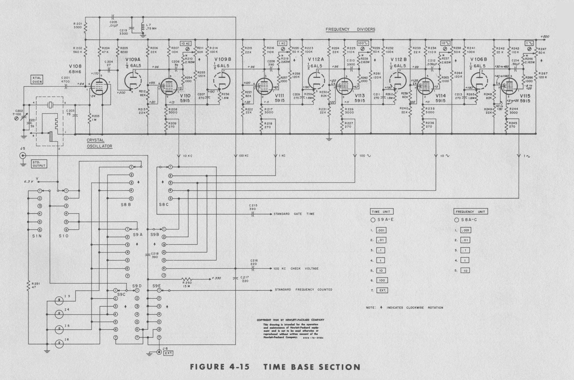
3-3 TIME BASE SECTION
The Time Base Section, supplies six standard frequencies: 100, 10 and 1 kilocycles, 100, 10 and 1 cycles per second. The Time Base consists of a crystal-controlled, 100-kc oscillator, a series of five 10 to 1 phantastron frequency dividers, and a plug-in decade divider. The plug-in decade dividerdivides the phantastron frequencies from the Time Base by 10 during frequency measurements and the input signal frequency by 10 during 10 PERIOD average measurement. The same high accuracy obtained from the crystal oscillator is also obtained with all divided frequencies when the circuits are in correct adjustment. The internal frequency standard for the 522B is a crystal-controlled, 100 -kc, modified Pierce or Colpitts oscillator. The crystal has a low temperature coefficient and is enclosed in a temperature controlled over to obtain a frequency stability of better than ten parts/million/week. The phantastron frequency dividers and the Decade Divider plug-in unit are described below.
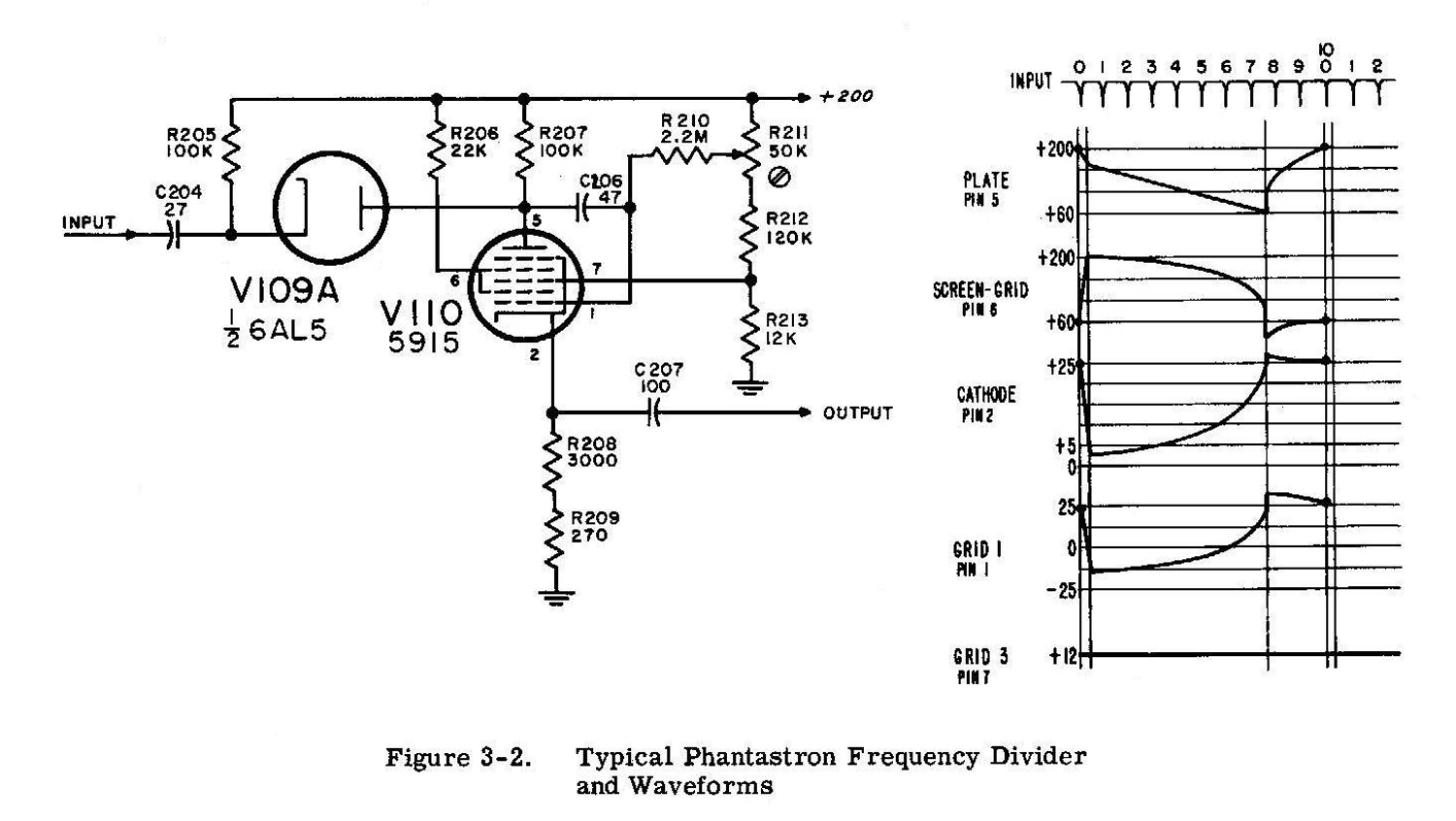
3-4 PHANTASTRON FREQUENCY DIVIDERS
The five standard gate times, .001, .01, 0.1, 1.0 and 10 sec, and two frequency units, milliseconds and seconds are obtained by dividing the 100-kc crystal-controlled frequency in steps of 10. Five 10:1 phantastron frequency dividers connected in cascade so that each divides the output of the previous one to produce standard frequencies of 10 kc, 1 kc, 100 cps and 10 cps. The operation of each divider is the same; only the value of one capacitor in each subsequent divider circuit is changed to obtain a ten-times longer time constant. The shapes of the output waveform from the dividers are similar, large unsymmetrical positive pulses. Division in a phantastron circuit is accomplished by adjusting the time constant of the circuit so that one period of phantastron operation lasts nine cycles of the input frequency actually a division of time. During the period of operation the phantastron is not affected by subsequent input cycles. After the period of operation, the phantastron is returned to its original state, ready to be triggered by the next input cycle. Consequently, the phantastron puts out one pulse for each ten cycles of input frequency; but note that it divides by 10 only at the one frequency – at other frequencies, if not readjusted, it divides by another factor, always producing pulses having practically the same period, regardless of the input frequency. To prevent any of the nine intermediate input cycles from prematurely operating the phantastron, the input signal is fed through a diode gate (V109A in Fig. 3-2) which blocks input cycles during the phantastron cycle. The blocking is accomplished by connecting the diode plate to the plate of the phantastron V110, and biasing the diode cathode a few volts below the plate. When the phantastron plate voltage, and thus the diode plate voltage, is high, the diode gate is open and the input signal is passed to the phantastron. When the phantastron is triggered by an input signal, its plate voltage drops and cuts off the diode, thus closing the gate. The phantastron plate voltage remains down (and the gate closed) during nine periods of the input frequency. At the end of its cycle the phantastron plate voltage rises, the diode gate is opened and the next (10th) cycle triggers the phantastron. The switching action in the phantastron circuit is as follows:
Refer to Fig. 3-2. Phantastron tube V110 is a special pentode in which the suppressor grid is tightly wound and can be used as a second control grid for the plate current, but not for the screen current. This feature makes it possible to switch the cathode current from plate to screen and vise versa. In this circuit the initial stable state has current going to the screen, 0 volts between control grid and cathode, and the cathode is 25 volts positive. The suppressor grid, being returned to ground, is thus negative, and blocks current to the plate such that cathode current goes to the screen grid. When a negative input pulse is applied to the phantastron control grid, the cathode voltage drops, the negative bias on the suppressor is instantaneously removed and the cathode current switches to the plate. Current continues to the plate until the charge on C206 discharges through the series resistor R210, the control grid voltage returns in a positive direction, cathode voltage following until the suppressor-to-cathode bias is again negative and the plate current cut off. Actually the voltage on the suppressor is maintained constant by voltage divider R211, 212, and 213, while the control-grid and cathode voltage move together as in a cathode follower to affect the shift in suppressor-grid bias. This shift in bias is held by the time constant of timing capacitor C206 and its series resistor R210, the positive charge curve being applied to the control grid of the tube. 3-5 DECADE FREQUENCY DIVIDER
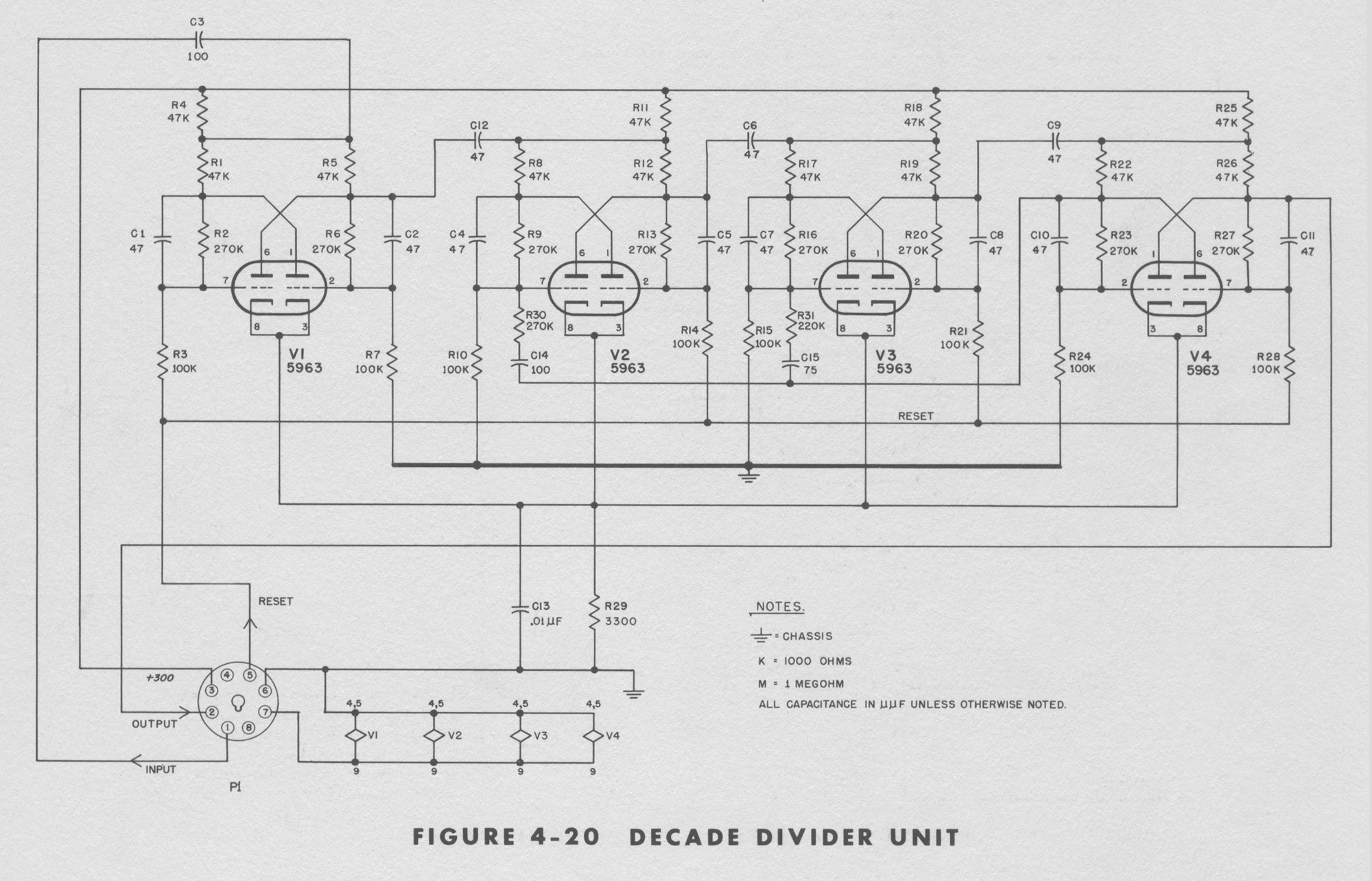
This unit is required primarily for dividing input frequencies by ten during 10 PERIOD AVERAGE measurement. It is also used during frequency measurement to divide the STD. GATE TIME timing signals from the Time Base so that STD. GATE TIMES from 0.001 to 10 seconds can be obtained from the standard frequencies of 10 kilocycles to 1 cycle per second obtained from the phantastron dividers. This unit, unlike the phantastron divider, is not sensitive to its operating frequency and will divide by ten at any frequency up to approximately 10 kilocycles. The operation of the decade divider is described below.
The Decade Divider consists of four cascaded binaries (bistable multivibrator), each triggered by the previous binary. Consequently, the cycles fed to the input are divided by two in the first binary (since the first pulse switches the binary to the opposite state and a second input cycle is required to return it to the original state) and again by two in the second binary (to make a total division by four) and so on, with an expected total division of Sixteen at the out-put of fourth binary. The desired division of ten is obtained by two feedback loops to the second and third binaries so that the eighth input pulse will be reset to the states they would be in had they received14 inpulses at the input. Consequently, after the ninth and tenth input cycles are received, the desired final output pulse is produced. This action is identical to the action of the AC-4A Decade Counter without its indicating lights, and in general the voltages and waveforms are the same.
The basic unit in a decade divider is a bistable multivibrator. The bistable multivibrator has two stable states, A-side conducting, B-side cut off, and vice versa. The circuit remains in either state until a negative pulse is applied to the common plate-load resistor to switch conduction to the opposite side. The grids are biased so that positive pulses will not switch the circuit. A negative input pulse does not affect the tube that is cut off but decreases conduction in the tube that is conducting. This will increase its plate voltage and in turn the grid voltage of the tube that is cut off. This regenerative action continues until conduction has switched from one tube to the other. The input is applied to the common plate circuit for simplicity, and since the plates and grids are interconnected the input signal is also applied to the grids.
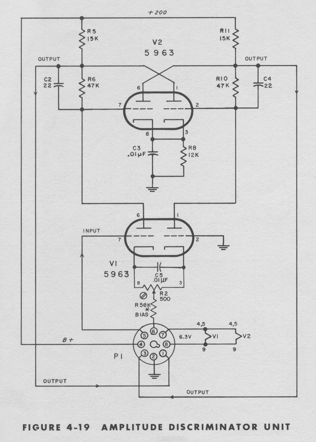
3-6 AMPLITUDE DISCRIMINATOR
Amplitude Discriminators are used to develop the fast-rise pulses required to operate subsequent binaries at a certain voltage level on the driving waveforms. For example: a sine wave applied to the input connector for frequency measurement must be converted into constant-amplitude, fast-rise pulses to operate the indicating counter units reliably. Input signals for period measurements must be converted into constant-amplitude, fast-rise pulses for precise opening and closing of the Counted Signal Gate. The essential part of the Amplitude Discriminator, a Schmitt Trigger, produces a large, sharp output pulse regardless of the shape of the signal that triggers. In addition, the discriminator can be adjusted by its sensitivity adjustment so that it will produce the output pulse when the input signal reaches a certain voltage level. Each discriminator is preceded by a differential amplifier so that a substantial trigger operating voltage is assured. The operation of the Schmitt Triggers is described below. A Schmitt Trigger consists of two amplifiers (twin-triode tube), each having both d-c plate-to-grid and cathode-to-cathode coupling from A triode to B triode. The circuit has two stable states; A side fully conducting, B side cut off; B side fully conducting, A side cut off. The circuits remain in either stable state until driven to the switching point by the differential amplifier. The d-c voltage level applied to the A-side grid determines which state the circuit will be in. If the grid voltage is more positive than a certain established level, A side will conduct and B side will not; if more negative than that same level, A side will cutoff and B side will conduct. Each time the A-side grid voltage crosses this threshold in the opposite direction, the circuit changes state. In practice, the threshold voltage is slightly more positive when moving the grid in a positive direction, and slightly more negative when moving the grid in a negative direction. The range between the two different voltage levels is the hysteresis of the circuit. Hysteresis is the limiting factor on sensitivity since the input voltage must swing through both hysteresis limits to produce an output pulse. The hysteresis of this circuit should be adjusted to give a sensitivity between 0.1 and 0.2 volt.
The manner in which the Schmitt Trigger changes state is as follows:
If A side is cutoff and B side is conducting, and the A side grid voltage is gradually made more positive, a grid voltage will be reached that will cause A side to conduct. When A side begins to conduct its plate voltage drops, which in turn drops the grid voltage of B side, and cuts B side off. As B side cuts off its cathode voltage goes more negative. Since the cathodes are direct coupled, this constitutes positive feedback and further drives A side into conduction until plate saturation is reached. This action is very rapid and when completed, the Schmitt Trigger is in the opposite stable state. It will remain in this state until the voltage level of the A-side grid is moved negatively until the lower hysteresis limit is crossed and A side is cutoff. The above process is then repeated in the opposite direction. 3-7 SIGNAL GATE SECTION
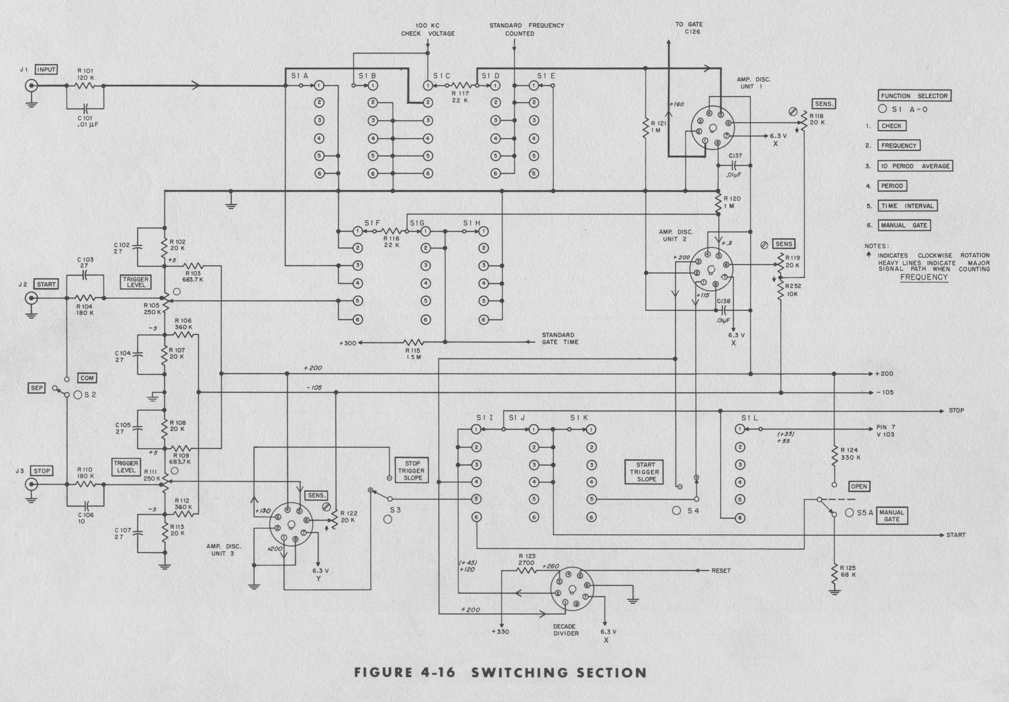
The circuits of the Signal Gate Section are shown in the Gating Section and Switching Section Schematic Diagrams at the rear of the manual. In order of signal progress through the section, it consists of the FUNCTION SELECTOR switch circuits which select the desired type of measurement; an Amplitude Discriminator plug-in unit which shapes the counted signal waveform into sharp pulses without affecting the important information – the frequency; the Counted Signal Gate which permits the signal- to-be-counted to pass to the indicating counters, or blocks it; the Gate Control Binary which opens and closes the Counted Signal Gate; the Decade Counter plug-in units described in the supplementary manual at the rear of this manual; and the Counter Reset and Display Time circuits. Each of these circuits is described separately in other paragraphs in this section.
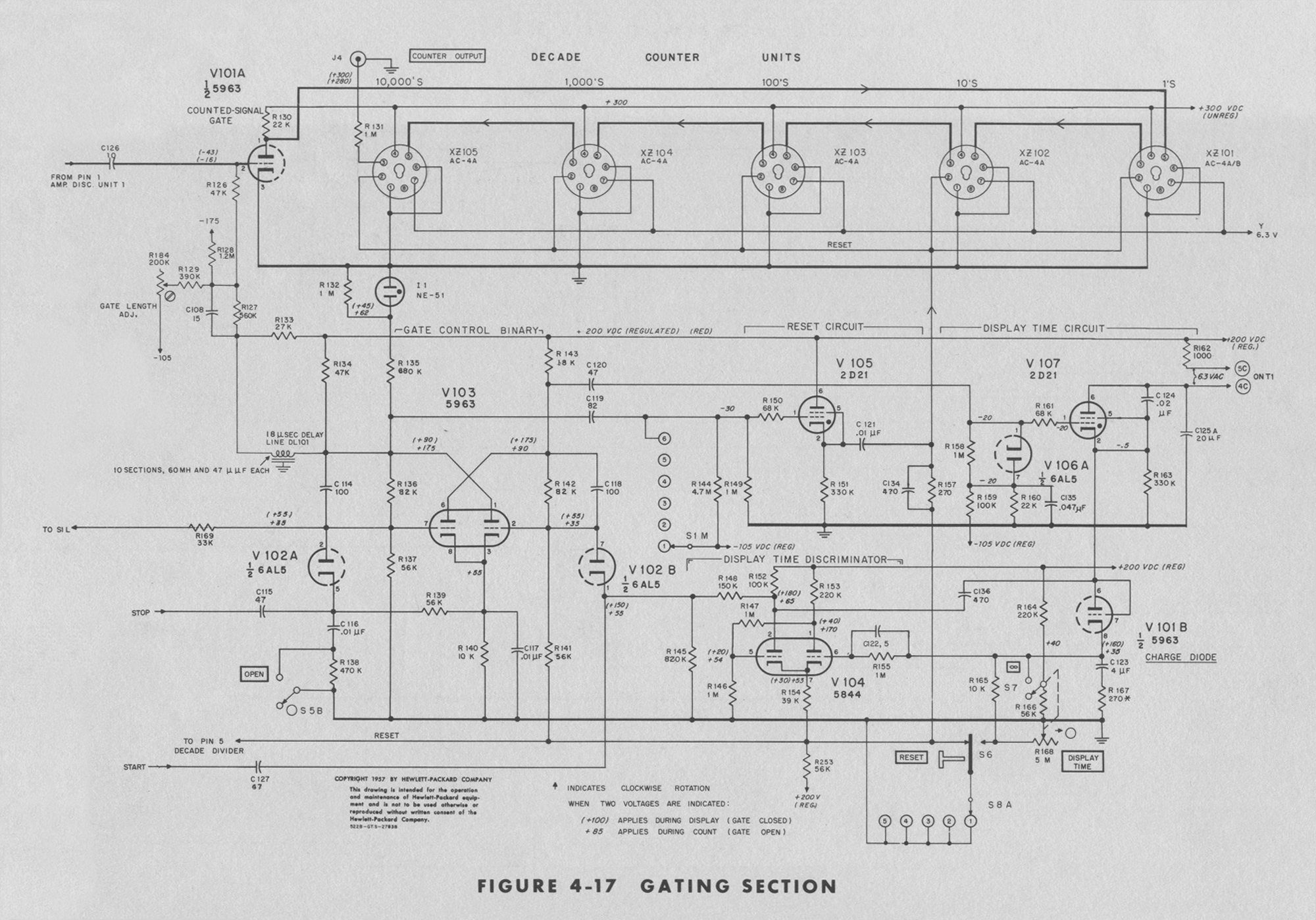
3-8 SIGNAL GATE
The Signal Gate is a single triode section of a dual-triode tube. The signal to be counted and the opening-closing control signals are both applied to the control grid of this tube. When the control signal holds the control grid below cutoff, the signal to be counted does not appear in the plate circuit. When the control signal returns the grid to its normal operating voltage, the Signal Gate is a normal amplifier and the signal to be counted is passed to the indicating counter units. For frequency measurements, the input signal is fed through the gate to the counters, while the gate is opened and closed by precision timing signals from the Time Base Section. For time interval and period measurements the gate is opened and closed by the input signal, while a standard frequency from the Time Base Section is fed through the gate to the counters.
3-9 GATE CONTROL BINARY
The Gate Control Binary, V103A and B opens and closes the Signal Gate by raising and lowering the grid voltage on the Gate tube. In addition, the Gate Binary starts the Reset Circuit just before it opens the Signal Gate, and also starts the Display Time Circuit when it closes the Signal Gate. The Gate Binary is actuated either by precision timing signals from the Time Base Section during FREQUENCY measurement, or by a signal from the INPUT connector for PERIOD and 10 PERIOD AVERAGE measurements, or by the front panel RESET button. The duty of Gate Control Binary is to trigger the Reset Circuit, open and close the Counted Signal Gate and start the Display Time Circuit. The Gate Control Binary is a bistable multivibrator which is triggered by negative pulses. For frequency measurement, the negative trigger pulses to start and stop the measurement are obtained from the Time Base Section and are applied to both sides of the binary. For time-interval measurements the negative trigger pulses to start and stop the measurements are obtained from the input connectors and can either be applied to both sides of the binary or they can be kept separate, with the start signal going to B side and the stop signal going to the A side of the binary. During automatically repetitive measurements, the negative trigger pulses alternately switch conduction from one side of the binary to the other side. Before a measurement is begun V103A is cut off, V103B is conducting and its low plate voltage cuts off the Counted Signal Gate tube. To begin a measurement a negative pulse applied to the binary cuts B side off, which immediately triggers the Reset Circuit and returns all indicating counter units to 0. Twenty microseconds later, the same signal having passed through a delay line, opens the Counted Signal Gate. The twenty-microsecond delay allows time for the circuits of the indicating counters to stabilize before they begin counting. The subsequent negative trigger pulse applied to the Gate Binary cuts V103A off (returning the binary to its original state), closes the Counted Signal Gate and starts the Display Time Circuit. The negative trigger pulses are coupled into the Gate Binary through two diodes serving as gates to the pulses. The gate to each grid is biased by the voltage at the opposite plate. When A side is conducting, its plate voltage is low and biases the B-side gate so that incoming negative trigger pulses to B side are blocked. Consequently only a conducting side can be triggered. The operation of the gate binary circuit is similar to the binary in the decade divider and decade counters.
3-10 DISPLAY TIME CIRCUIT
The Display Time Circuit determines how long an answer will be displayed before the next count is begun. Display time is started by the Gate Binary when it closes the Counted Signal Gate, and the Display Time Circuit prevents a new trigger pulse from reaching the Gate Binary to and start a new count. This is done by biasing the Gate Binary’s B-side (start channel) diode gate beyond cutoff. The counter will then continue to display the last count until the start-channel diode gate is reopened. The Display Time Circuit’s action begins when the Gate Binary B side fires the Display Time Thyratron as the A side closes the Counted Signal Gate. Display Time Thyratron V107 starts the display time by charging C123 positively and switching Display Time Discriminator V104 so it produces a positive output voltage. The positive output voltage applied to the cathode of Diode Gate V102B, closes the gate and prevents trigger pulses from reaching the Gate Binary. The display holding action continues until C123 discharges through R165 and decreases the grid (pin 6) voltage on Display Time Discriminator V104 and retriggers V104 to produce a negative output voltage. The negative output voltage from the Display Time Discriminator reopens Diode Gate V102B and permits the next negative pulse to operate the Gate Binary and start a new measurement.
3-11 RESET CIRCUIT
The Reset Circuit generates a strong positive pulse which resets all indicating counter units to “0” before each new count is begun. During automatic, repetitive measurements, Reset Thyratron V105 generates this positive pulse when it is triggered by the same positive pulse from the A side of Gate Binary V103 that opens the Counted Signal Gate to start a new count. The pulse to the Signal Gate is delayed twenty microseconds by Delay Line DL 101 to give the counter circuits time to reset and stabilize before they receive the new signals. The manual RESET button generates a positive pulse for resetting the counters by ungrounding the reset wire so that its potential automatically rises approximately 40 volts positive. The positive reset pulse for the counters also resets the decade divider to the beginning of its division cycle so that it will divide the next input signal by ten.
3-12 TIME INTERVAL INPUT CIRCUITS
During time interval measurements, the measurement start and stop input signals are fed to separate, identical Amplitude Discriminators which generate strong trigger pulses as the input voltage levels pass the levels indicated by the TRIGGER LEVEL VOLTS controls. The sharp pulses produced by the Amplitude Discriminators are fed directly to the Gate Control Binary which in turn operates the Counted Signal Gate to make the measurement. The TRIGGER LEVEL VOLTS controls in the START and STOP input circuits determine the input voltage level that will start and stop a time interval measurement by simultaneously attenuating the input signal and applying a negative bias voltage to the Amplitude Discriminators. When the TRIGGER LEVEL controls are set to zero, there is a fixed attenuation of 4 to 1 and no d-c bias on the Amplitude Discriminator, which triggers as its input signal voltage passes through zero volts. When the TRIGGER LEVEL control is set to +100, there is an attenuation of 20 to 1 and a d-c bias of -5 volts so that the input signal is reduced to +5 volts, just sufficient to override the -5 volt bias and trigger the Amplitude Discriminator.Any d-c voltage accompanying the signal applied to the input connectors will alter the d-c bias and render the control calibrations inaccurate.
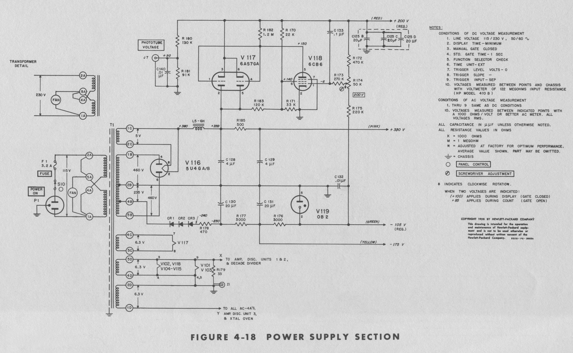
3-13 POWER SUPPLY
The power supply section supplies +330 vdc unregulated at 75 ma, +200 vdc regulated at 80 ma, -105 vdc regulated at 25 ma and -175 vdc unregulated for the circuits of the counter. The positive regulated voltage is obtained from an electronic regulator circuit, V117, V118 and V119 while the negative regulated voltage is obtained from gaseous voltage regulator tube V119. The unregulated voltages are obtained from the power sources for the voltage regulators. The +200 volt regulator is a two stage, direct coupled, feedback amplifier. V117 is the series regulator tube and carries the total load current. V118 controls the resistance of V117 to keep the output voltage constant over a wide range of load currents and line voltage fluctuations. Any increase in output voltage will make the grid of V118 more positive; this will increase its plate current and in turn decrease the bias on V117. Increasing the bias on V117 increases its resistance and return the output voltage to the original value. A decrease in output voltage will have the reverse effect on the circuit. V119, a voltage regulator tube, supplies a constant fixed bias for V118.»
§§§
Per consultare la prima parte scrivere “522B” su Cerca.
Foto di Claudio Profumieri, elaborazioni e ricerche di Fabio Panfili.
Per ingrandire le immagini cliccare su di esse col tasto destro del mouse e scegliere tra le opzioni.