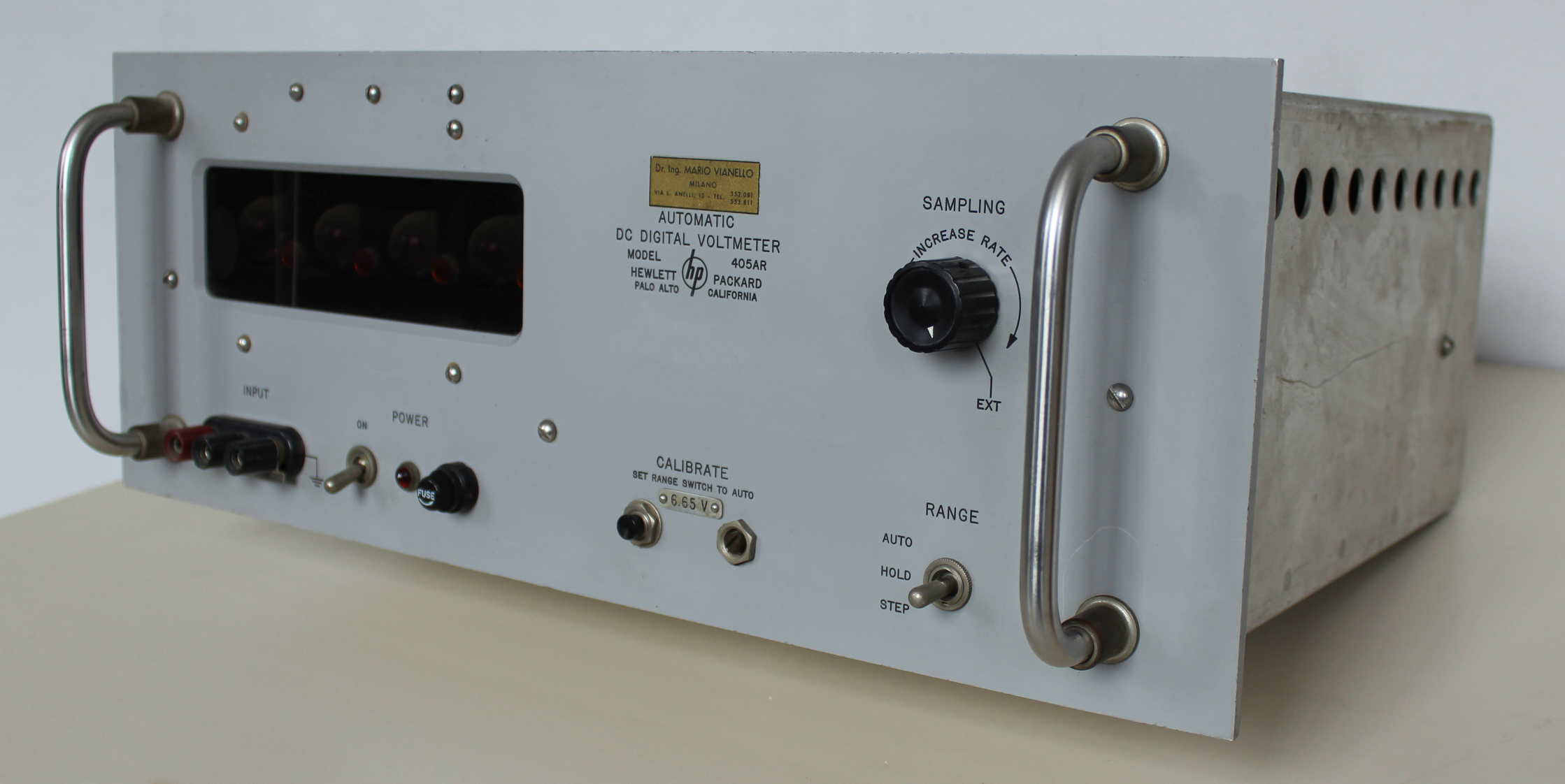
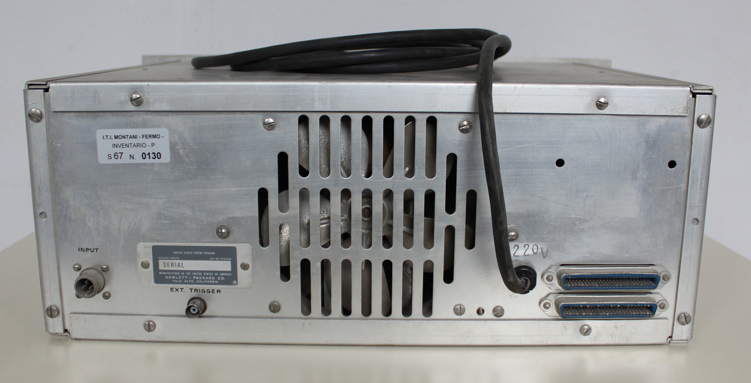
 Automatic DC Digital Voltmeter HP 405 AR, della Hewlett Packard Palo Alto California. Serial 129-00327. Seconda parte
Nell’inventario D del 1956, in data 7 giugno 1960, al n° 1801 si legge: “Fondazione Carlo e Giuseppe Piaggio. Voltmetro elettronico hp mod. 405AR. Destin. RAD.”.
Importatore Dr. Ing. Mario Vianello – Milano.
In internet è facile trovare molte informazioni al riguardo ad esempio agli indirizzi:
http://www.hpl.hp.com/hpjournal/pdfs/IssuePDFs/1959-01.pdf
http://hpmemoryproject.org/wa_pages/wall_a_page_02.htm
http://www.hparchive.com/Catalogs/HP-Catalog-1960-Short-Revised.pdf
http://hparchive.com/Catalogs/HP-Catalog-1963.pdf
Riportiamo qui di seguito alcune parti del manuale di istruzioni conservato presso il “Museo ombra”.
Il testo prosegue dalla prima parte.
§§§
«2-5 OPERATION WITH DIGITAL RECORDERS
With –hp- Model 560A or 561B Digital Recorder you can obtain permanent printed records of 405A measurements. An example of printed records is shown below. The 3rd, 4th and 5th columns from the right show the digits that appear on the 405A. The 2nd column from the right indicates polarity, blank for positive and (-) for negative. The right-hand column indicates decimal location from the right.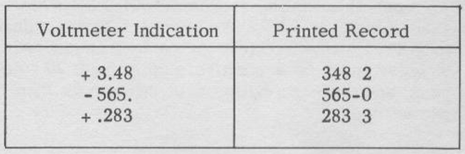 The 405A can drive the 561B directly; the standard 561B cable makes the necessary connections between the voltmeter and recorder. However, the 405A-95C Digital Recorder Adapter is required to connect the 405A to the 560A. The adapter mates with the 100-pin output connector on the rear of the 405A and is held in place by two machine screws. The standard 560A cable connects to the adapter. When connecting either recorder to the 405A, be sure both the recorder and 405A are turned off.
CAUTION
The 405A chassis is connected to power-line ground through the adapter/560A system. Do not connect the voltmeter common lead roan off-ground potential while the 560A is connected to the volt-meter.
————
2-6 ELECTRICAL OUTPUT INFORMATION
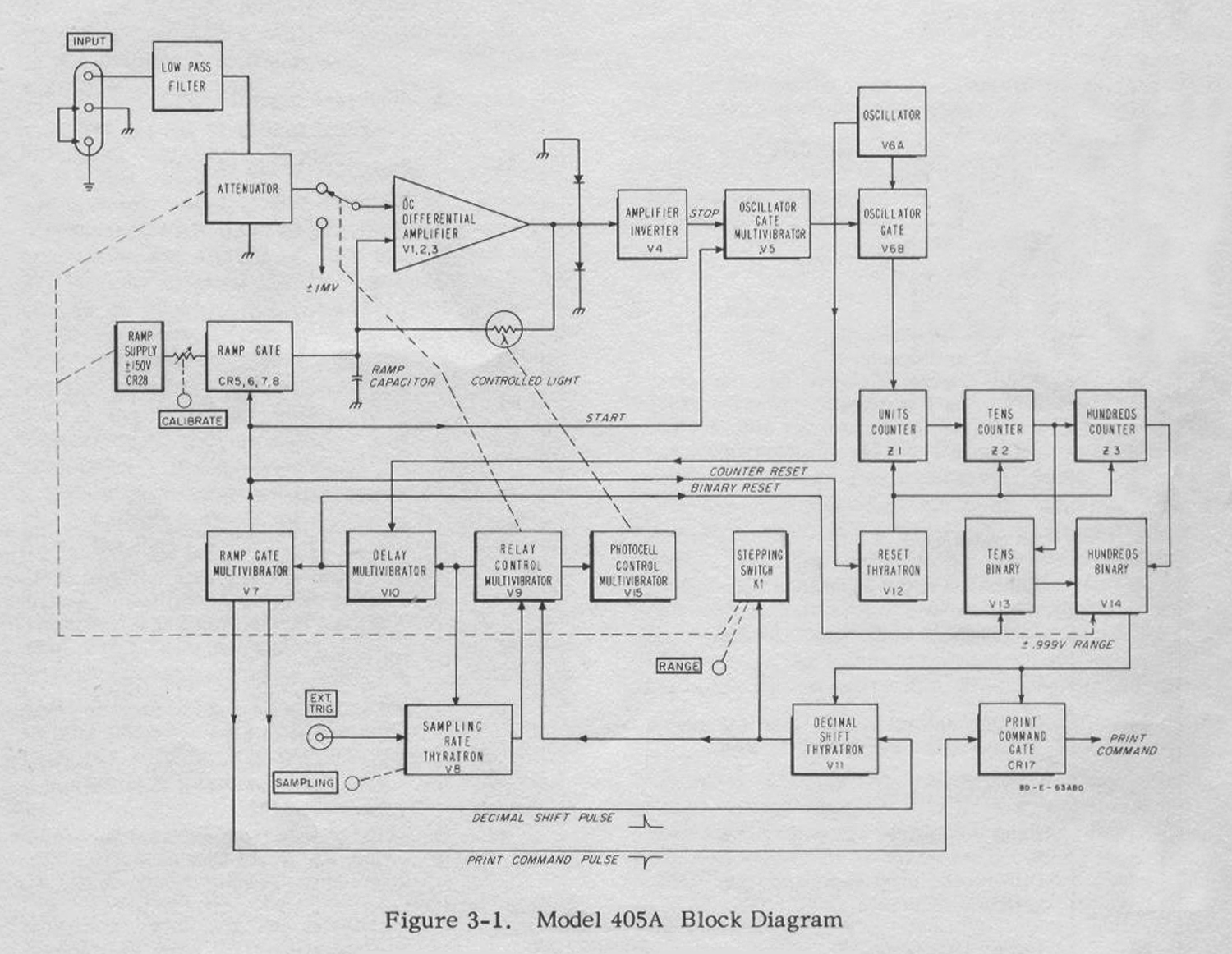
You can use the electrical information provided by the 405A for other purposes than operating a recorder. For example, you might use the information to operate a remote readout identical to the one in the instrument or to record voltage information on punched cards or tape. Table 2-1 gives full details of the information available and the counters display the total number of pulseswhich passed through the gate.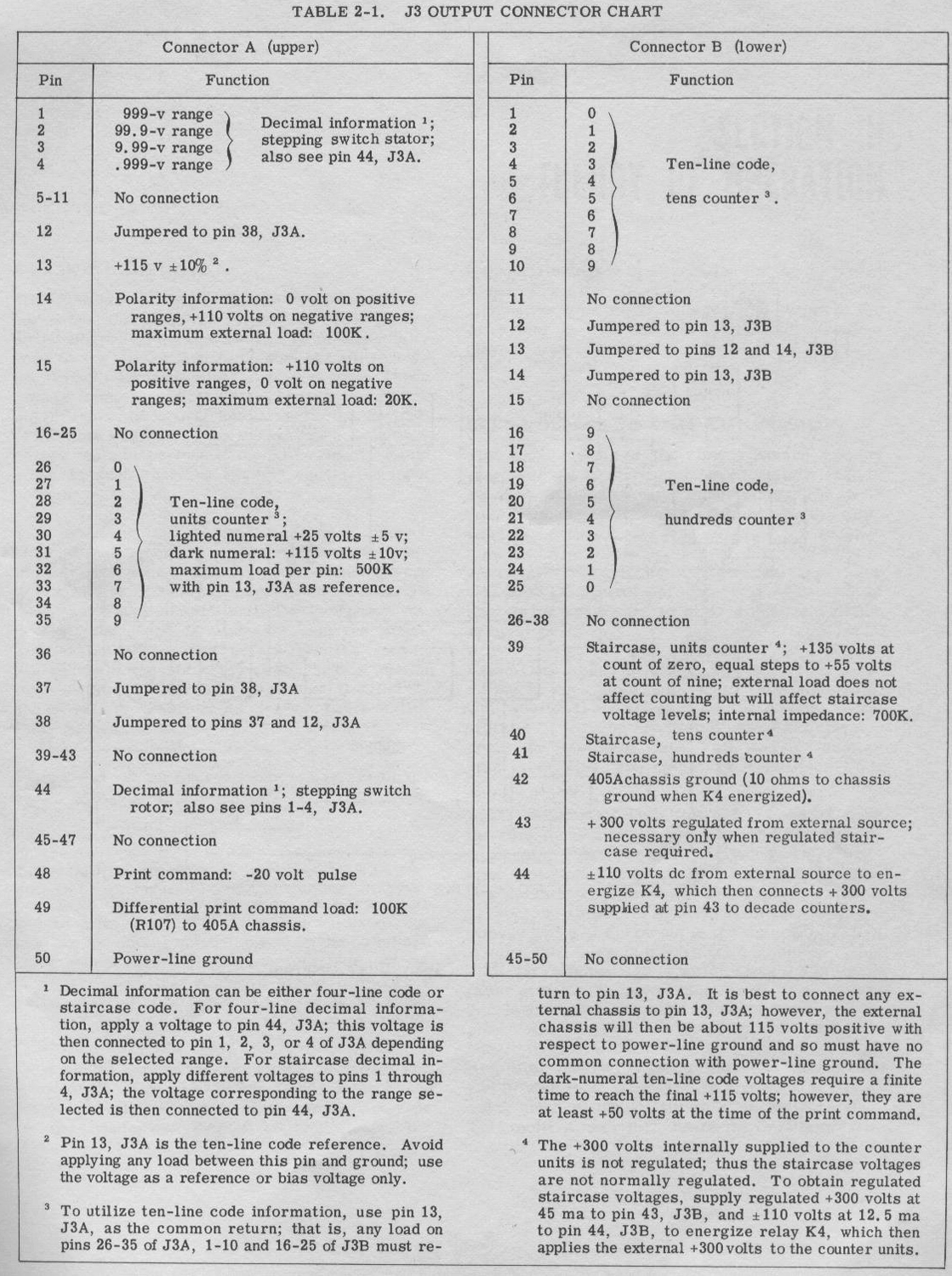 The Ramp Gate Multivibrator returns to its stable condition, closing the Ramp Gate, about 30 milliseconds after it starts the ramp; and should there be no output from the amplifier, the Oscillator Gate Multivibrator returns to its stable condition at about the same time. Thus the instrument can count to about 1-1/2 times full scale.
OMISSIS
Nel processo di scanner abbiamo inavvertitamente saltato la pagina 3.1 e, nel redigere il testo, ci troviamo per ora nell’impossibilità di accedere al manuale di istruzioni per la chiusura del Montani causa Covid 19 (o SARS-COV2). Ce ne scusiamo con i visitatori.
 3-4 ZERO-SETTING THE VOLTMETER
To insure that the ramp always starts from the correct voltage, the ramp is zero-set prior to each measurement. Two multivibrators, Relay Control Multivibrator V9 and Photocell Control Multivibrator V15, zero-set the ramp. The Relay Control Multivibrator energizes a relay which applies il mv to the input grid of the amplifier. The polarity of this voltage is opposite to the polarity of the displayed range and assures a readout of .000 when the instrument measures .000 volt. The Photocell Control Multivibrator illuminates a photocell in a feedback loop around the amplifier. When the photocell is illuminated its resistance drops to a low value, and it applies total negative dc feedback to the amplifier. Thus any voltage at the amplifier output is totally fed back and essentially cancelled. Cancellation is not complete because of the internal unbalance and drift of the amplifier and the ± 1 mv applied to the amplifier input grid. However, amplifier output and ramp grid input come to less than ± 100 mv.
The ramp is zero-set at this time, for the ramp capacitor is connected to the ramp grid of the amplifier and so charges to the feedback voltage. The ramp capacitor maintains this voltage on the ramp grid between the time the Photocell Control Multivibrator opens the feedback loop and the start of the ramp, and amplifier drift is not fast enough to upset the balance in the time of a single measurement. Thus the ramp always starts from the zero-set value.
Amplifier gain jumps from unity to over 1000 when the feedback loop is opened. Amplifier output (less-than ± 100 mv) then becomes less than ± 100 µvolt when referred to the input. Therefore the voltmeter is zero-set to within 100 µvolt of zero.
The Photocell Control Multivibrator opens the feedback loop (by turning off the light shining on the photocell) before the Relay Control Multivibrator de-energizes the relay. Thus the attenuated input voltage is applied to the amplifier after the feedback loop opens and cannot upset ramp zero. 3-5 THE MEASUREMENT PROCESS
Sampling Rate Thyratron V8 starts the measurement process by triggering the Relay Control Multivibrator, V9. The Relay Control Multivibrator immediately triggers Photocell Control Multivibrator V15, and these two multivibrators zero-set the ramp. After about 80 msec, the Photocell Control Multivibrator returns to its stable condition, darkening the photocell. Some 30 msec later the Relay Control Multivibrator returns to its stable condition, de-energizing the relay and triggering Delay Multivibrator V10. The Delay Multivibrator allows the relay to completely dc-energize before the start of the ramp. The delay is about 4 msec.
When the Delay Multivibrator returns to its stable condition, it triggers the Ramp Gate Multivibrator, V7, to start the ramp and open the Oscillator Gate, V6B. Oscillator V6A synchronizes the return of the Delay Multivibrator to its stable condition. Thus there is no count ambiguity at the start of the ramp.
When the ramp voltage equals the attenuated input voltage, the DC Differential Amplifier closes the Oscillator Gate, and the readout indicates the voltage applied to the instrument.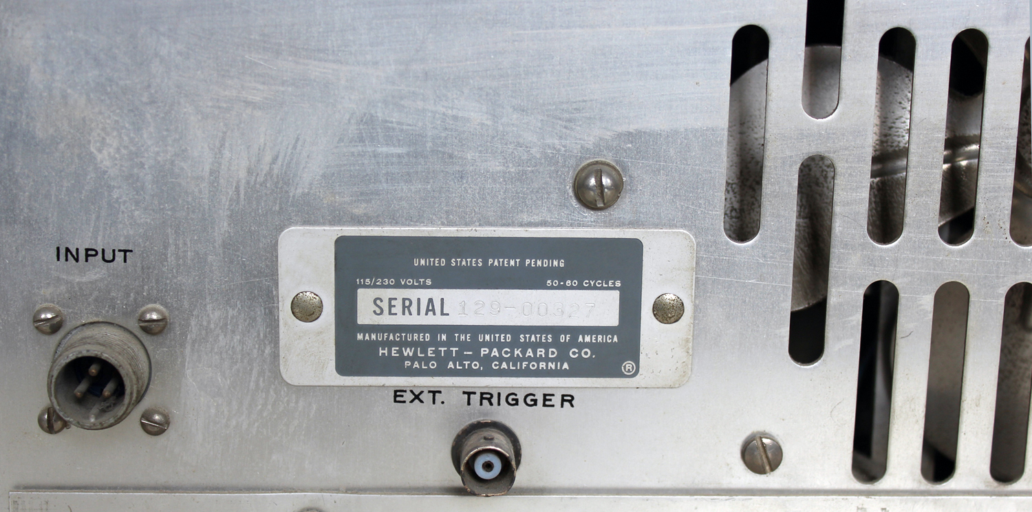 3-6 CHECKING RANGE
During each measurement the 405A checks the range by monitoring the output of the Tens and Hundreds Counters. If there is no output from the Tens Counter, the range is too high, for the ramp voltage equals the attenuated input voltage before the counters register 100 counts. If the Hundreds Counter produces an output, the range is too low or of the wrong polarity, for the counters count off scale before the ramp voltage equals the attenuated input voltage. Thus the range is correct only when the Tens Counter produces at least one output pulse, but the Hundreds Counter produces none.
Tens Binary V13 and Hundreds Binary V14 do the monitoring. The Tens Binary is reset by Delay Multivibrator V10 when that multivibrator triggers the Ramp Gate Multivibrator. The Tens Binary in turn resets the Hundreds Binary. (Binaries have two stable conditions. Hereafter, condition 0 is the reset condition; condition 1, the non-reset condition.) With no output from the Tens Counter, both binaries remain in condition 0. The first output pulse from the Tens Counter switches the Tens Binary to condition 1, and the Tens Binary immediately switches the Hundreds Binary to condition 1 also. Succeeding pulses from the Hundreds Counter switches the Hundreds Binary back to condition 0. Succeeding pulses have no effect. Therefore, if the measurement ends with the Hundreds Binary in condition 1, the range is correct; if the measurement ends with the Hundreds Binary in condition 0, the range is wrong.
There is a direct reset line from the Delay Multivibrator to the Hundreds Binary (not shown in Figure 3-1); so the Delay Multivibrator directly resets the Hundreds Binary in the event the Tens Binary is in condition O and the Hundreds Binary in condition 1. However, this combination seldom occurs. To prevent continual ‘recycling when the 405A measures voltages from + 0.099 to -0.099 volt, the Hundreds Binary is reset to condition 1 on the +999 and -.999 volt ranges. Thus the instrument shifts from these ranges only after off-scale counts.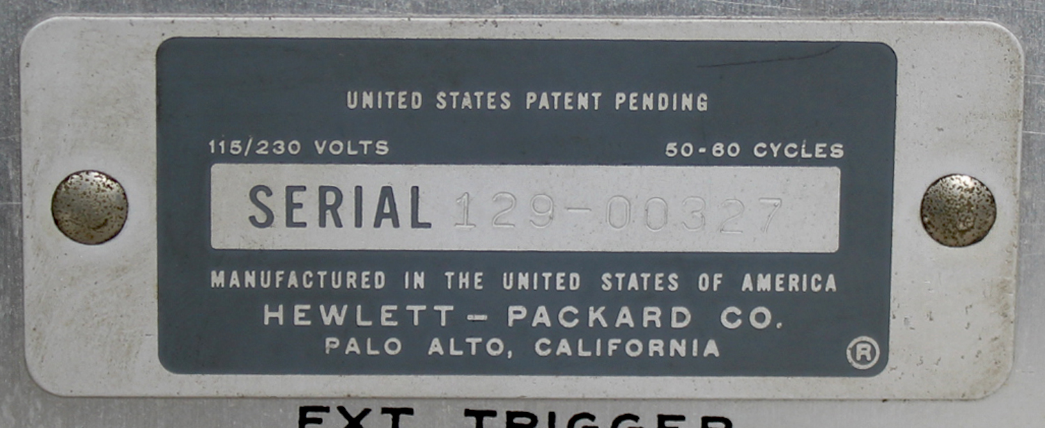 3-7 DECIMAL SHIFT CONTROL
The Hundreds Binary determines whether or not the 405A shifts range by controlling Decimal Shift Thyratron V11 and Print Command Gate CR17. When in condition 1 (correct range), the Hundreds Binary holds the Decimal Shift Thyratron off and opens the Print Command Gate. When in condition 0 (wrong range), the Hundreds Binary lets the Decimal Shift Thyratron fire if triggered and closes the Print Command Gate.
When the Ramp Gate Multivibrator returns to its stable condition and closes the Ramp Gate, it applies a positive pulse to the Decimal Shift Thyratron and a negative pulse to the Print Command Gate. If the range is correct, the negative pulse passes through the Print Command Gate to, be used as a trigger for a remote recorder. The Decimal Shift Thyratron is held off. If the range is wrong, the Print Command Gate is closed, but the positive pulse fires the Decimal Shift Thyratron. The Decimal Shift Thyratron then shifts the instrument to the next more positive range (by moving Stepping Switch K1 one step) and triggers Relay Control Multivibrator V9 to start another measurement.
When triggered, the Relay Control Multivibrator triggers Sampling Rate Thyratron V8. The Sampling Rate Thyratron then cannot fire during a measurement started by the Decimal Shift Thyratron.
To prevent continual recycling when the 405A measures voltages from + 0.099 to -0.099 volt, the Hundreds Binary is reset to condition 1 on the +.999 and -.999 volt ranges. Thus the instrument shifts from these ranges only after off-scale counts».
§§§
OMISSIS MAINTENANCE
Per consultare la prima parte scrivere “405AR” su cerca.
Foto di Claudio Profumieri, elaborazioni e ricerche di Fabio Panfili.
Per ingrandire le immagini cliccare su di esse col tasto destro del mouse e scegliere tra le opzioni.