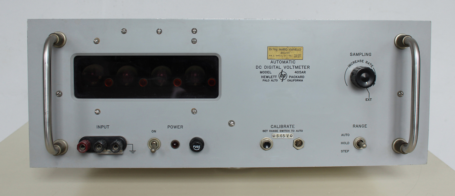
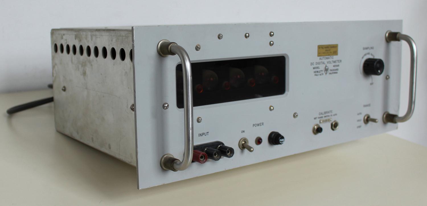
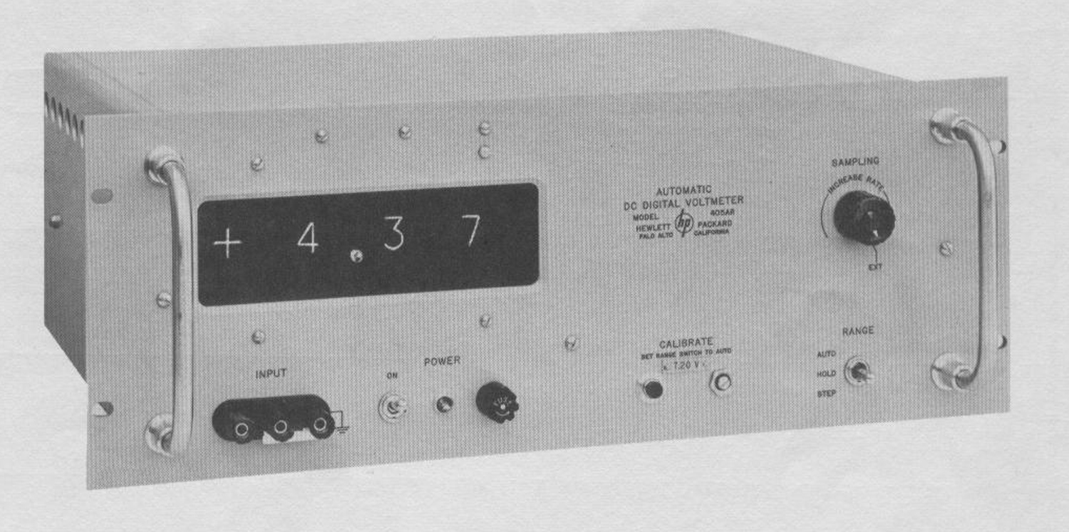
 Automatic DC Digital Voltmeter HP 405 AR, della Hewlett Packard Palo Alto California. Serial 129-00327. Prima parte.
Nell’inventario D del 1956, in data 7 giugno 1960, al n° 1801 si legge: “Fondazione Carlo e Giuseppe Piaggio. Voltmetro elettronico hp mod. 405AR. Destin. RAD.”.
Importatore Dr. Ing. Mario Vianello – Milano.
In internet è facile trovare molte informazioni al riguardo ad esempio agli indirizzi:
http://www.hpl.hp.com/hpjournal/pdfs/IssuePDFs/1959-01.pdf
http://hpmemoryproject.org/wa_pages/wall_a_page_02.htm
http://www.hparchive.com/Catalogs/HP-Catalog-1960-Short-Revised.pdf
http://hparchive.com/Catalogs/HP-Catalog-1963.pdf
Riportiamo qui di seguito alcune parti del manuale di istruzioni conservato presso il “Museo ombra”.
§§§
«SECTION I
GENERAL DESCRIPTION
1-1 IDENTIFICATION
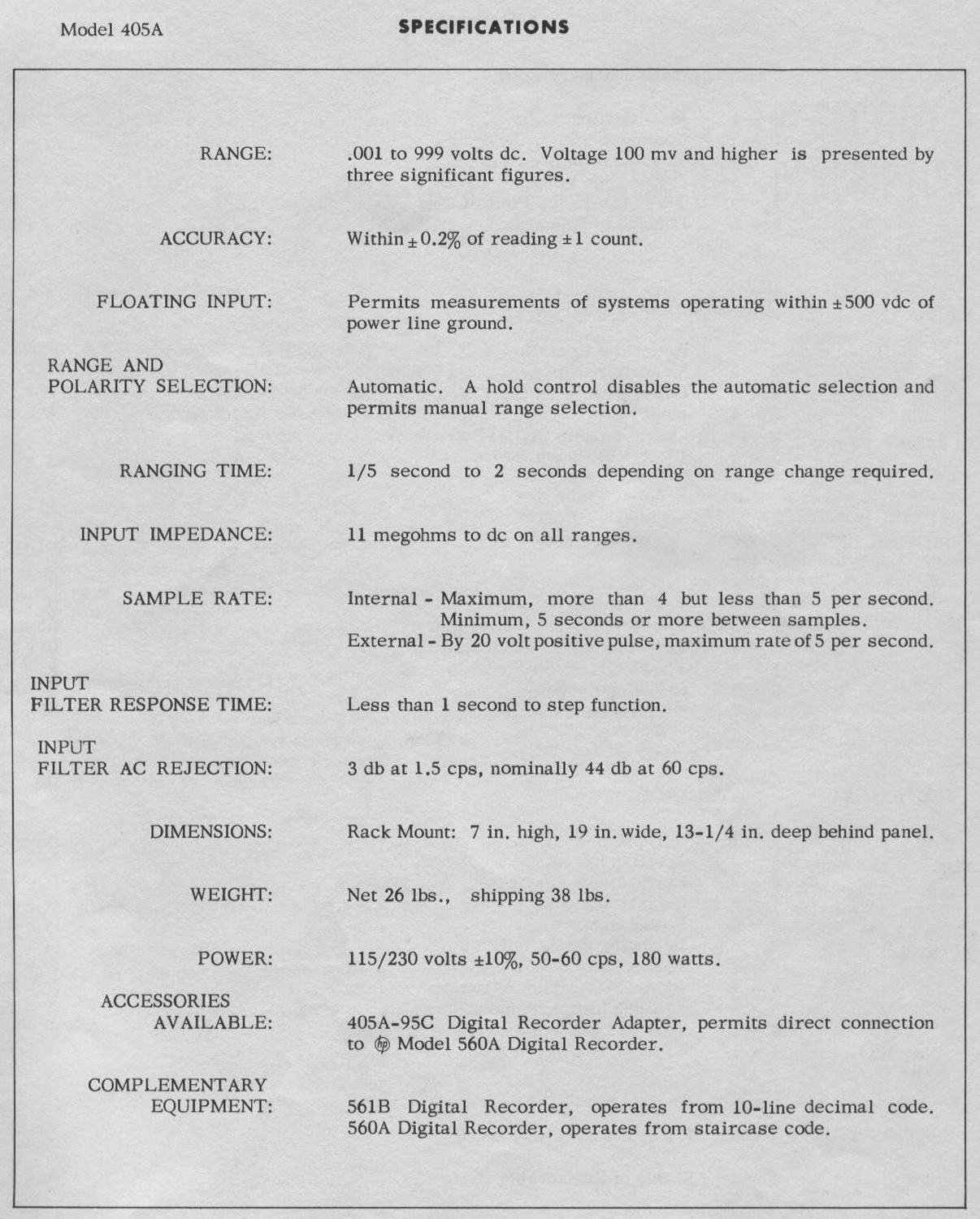
The -hp- Model 405A Automatic DC Digital Voltmeter measures positive or negative voltages from 1 millivolt to 999 volts. It can select range and polarity automatically to display voltages from 100 millivolts to 999 volts to three significant figures.
1-2 COOLING
The 405A uses forced-air cooling to maintain tolerable temperatures within the cabinet. Exhaust fan and air outlet are located on the instrument rear; air intakes, on the sides. Allow at least 2 in. clearance about instrument sides and rear for proper ventilation.
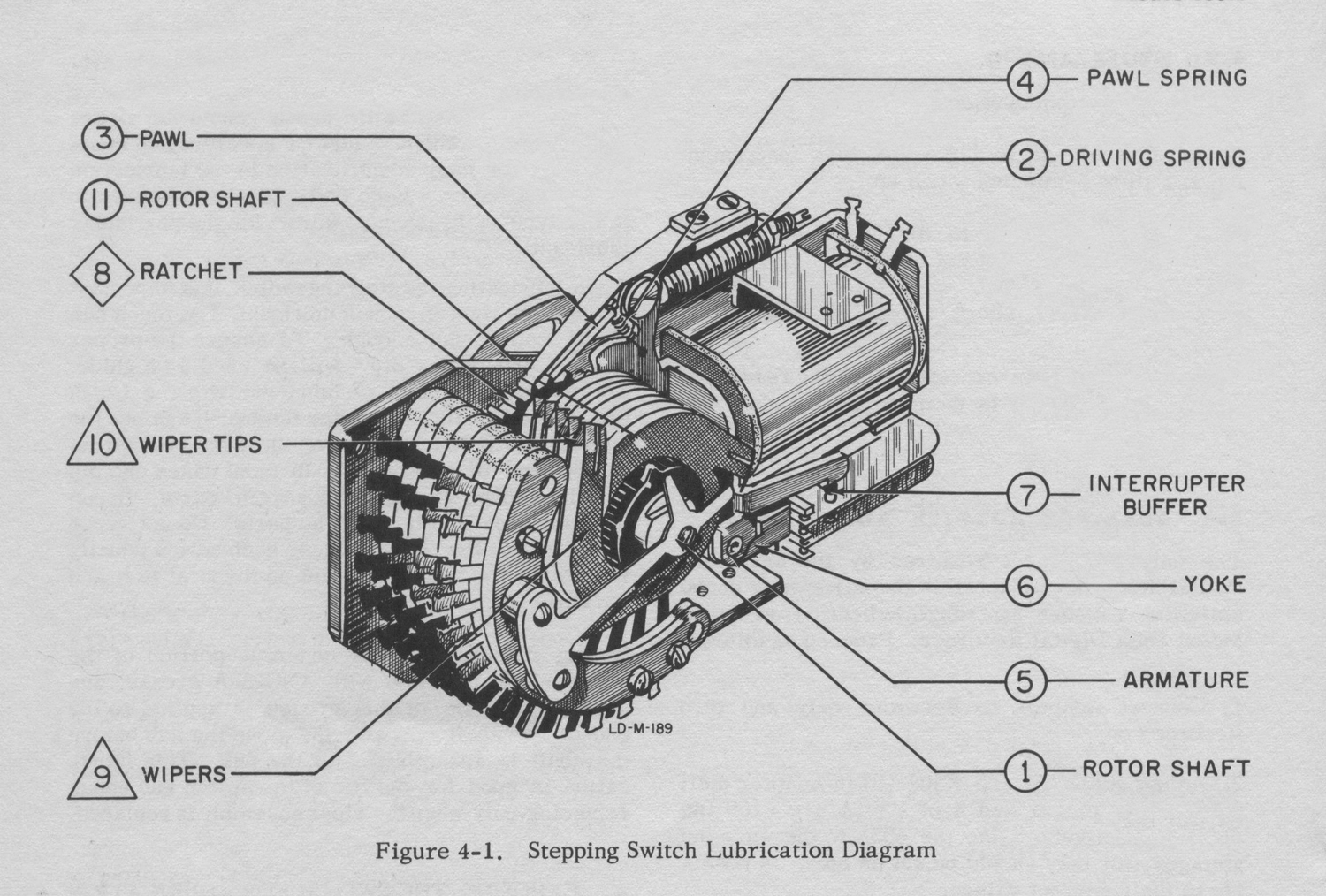
1-3 STEPPING SWITCH
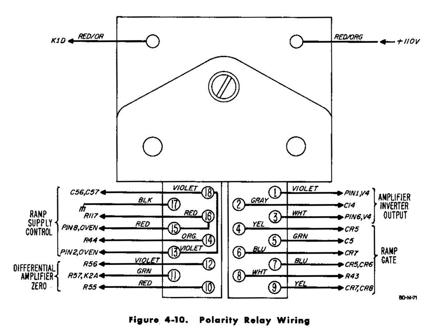
The 405A uses a relay-operated stepping switch for ranging. Although the switch requires infrequent service, it is important to service it when due. See Section IV, Maintenance.
1-4 POWER LINE VOLTAGE
The 405A is normally wired for use from a 115-volt, 50-60 cps power source. To convert it for use from a 230-volt power source, change the
dual 115-volt primary windings of the power transformer from a parallel combination to a series combination. See the schematic diagram for details. At the time of conversion, change the line fuse from a 2-ampere, slow-blow type to a 1-ampere, slow-blow type.
1-5 THREE CONDUCTOR POWER CABLE
This instrument is equipped with a three conductor power cable terminated with a polarized connector recommended by the National Electrical Manufacturers’ Association (NEMA). The third green conductor is terminated in a round pin added to a standard two-blade connector. With the NEMA connector plugged into an appropriate receptacle, the third lead grounds the instrument cabinet for the protection of operating personnel. To use the NEMA connector in a two-contact receptacle, you should use a three-prong to two-prong adapter. The ground lead emerges from the adapter as a short green lead which should be connected to a grounded receptacle box.
1-6 DAMAGE IN SHIPMENT
Inspect and operate this instrument upon receipt. Section IV, Maintenance, contains a performance check which is a good test as part of incoming quality control inspection. If there is any damage, see the “Claim for Damage in Shipment“ sheet in this manual.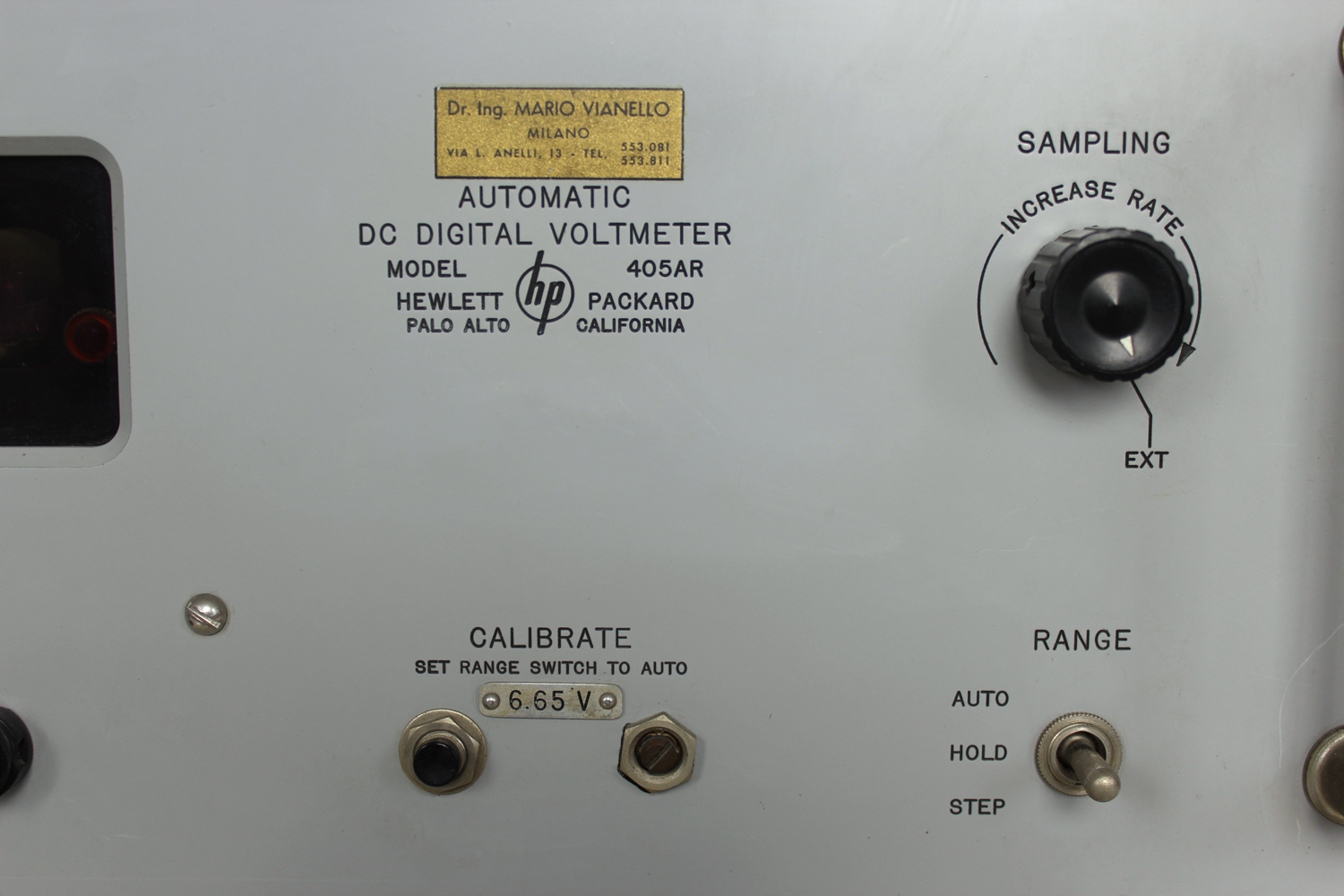
 SECTION II
OPERATING INSTRUCTIONS
2-1 AUTOMATIC OPERATION
1) Turn instrument ON. Instrument can be used within 1 minute of turn on, but requires 15 minutes warm up before calibration against internal standard brings it within specified accuracy. See paragraph 2-3.
2) Set SAMPLING control to desired sampling rate.
To control sampling rate externally, set SAMPLING control to EXT and connect triggering signal to EXT TRIGGER connector on instrument rear.
Trigger must be a positive step at least 20 volts peak and have repetition rate no greater than 5 per second.
NOTE
The instrument requires about 1 second to fully respond to sudden input-voltage changes (see paragraph 2-4); therefore delay the external trigger about 1 second after any sudden change in applied voltage.
———–
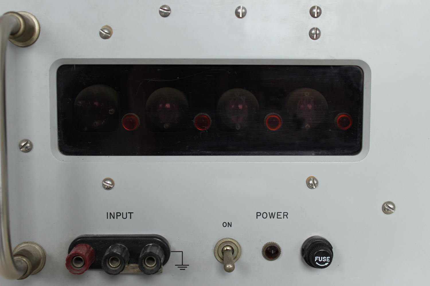
3) Connect voltage to he measured to INPUT connector and read its value. A parallel INPUT connector is located on instrument rear.
CAUTION
When measuring voltage between two points which are both off ground potential, remove the shorting strap between power-line ground and chassis-ground terminals of front-panel INPUT connector.
————
2-2 MANUAL OPERATION
Manual operation permits manual selection of range and is intended for measuring voltages which produce readings of 999 or 100 regardless of decimal position. In either case, a varying input voltage might cause the instrument to continuously change ranges if it is operating automatically. Manual operation permits measurement of some voltages to four figures, for the instrument can measure to about 150% of full scale. By holding the instrument on the range just below the correct range, you obtain the second, third, and fourth figures from the readout; the first figure, which is lost, is always 1. However, instrument accuracy deteriorates above full scale. Manual operation is convenient for measuring a series of voltages quite close in value, for the instrument will not cycle through its ranges as you move the probe from one test point to another.
1) Set RANGE switch to HOLD. Instrument will remain on its displayed range.
2) To change ranges, set RANGE switch to STEP. This is a spring-loaded position, and switch returns to HOLD when released. Instrument steps to next more positive range each time you release RANGE switch from STEP except that three blank positions occur between +9.99 and +99.9 volt ranges. The decimal point is not lighted on the blank ranges.
2-3 CALIBRATION
The 405A has an internal secondary voltage standard to check its calibration. The push-button CALIBRATE switch, located on the front panel, applies this voltage to the instrument and disconnects the INPUT connector. Calibrate the instrument, after sufficient warm up, each time you turn it on. Once set, calibration need seldom be checked. Proceed as follows:
1) Turn instrument ON and allow 15-minute warm up.
2) Set SAMPLING control to maximum sampling rate (full clockwise but not to EXT).
3) Set RANGE switch to AUTO.
4) Note voltage indicated below CALIBRATE engraving on front panel. This is the internal secondary standard voltage.
5) Press CALIBRATE switch and adjust CALIBRATE control until readout agrees with internal secondary standard voltage.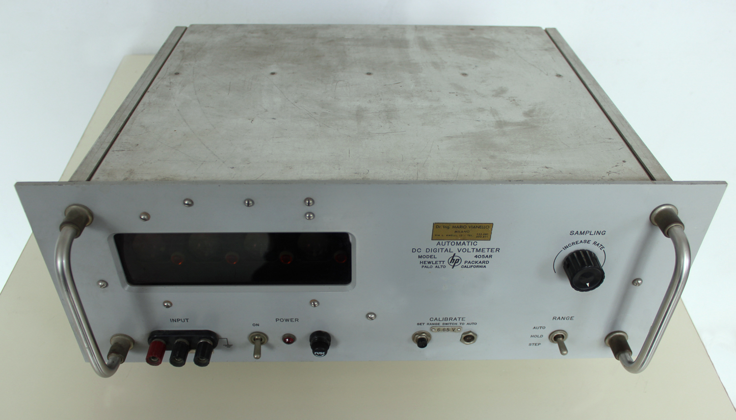 2-4 INPUT FILTER
The 405A measures instantaneous dc voltages. To avoid readout variations due to superimposed ac signals, the instrument has a low-pass RC filter at its input. The filter has a sharp cutoff and attenuates 60-cps signals about 50 db. Thus a 60-cps signal with a peak value equal to full scale of the displayed range typically causes a readout variation of ± 4 counts. Since the filter is at the input, it becomes charged to the full value of the input voltage. With the input open-circuited (probe lifted off test point), the filter capacitors must discharge through the input attenuator, and after 2 seconds they still have about 37% of their original charge. (You can see the discharge by watching the readout decrease after the probe is removed from a voltage source.) Therefore, if you quickly change the probe from a high- voltage point to a low-voltage point, you will apply nearly the full high voltage stored in the filter capacitors to the low-voltage point through 500K resistance. If the low-voltage point happens to be a high-impedance point such as a vacuum tube grid or, possibly, a transitor element, the voltage applied through the probe may upset circuit operation to the point that the circuit will damage itself.
A GOOD OPERATING PRACTICE IS TO TOUCH THE PROBE TO GROUND BRIEFLY OR ALLOW THE FILTER SUFFICIENT TIME TO DISCHARGE WHEN CHANGING THE PROBE FROM HIGH- VOLTAGE POINTS TO LOW-VOLTAGE POINTS.
In any case be sure the readout is less than the expected voltage before connecting the probe into a low-voltage circuit. The input filter makes instrument response to step functions about 0.75 second compared to about 0.2 second between successive samplings at maximum sampling rate. If you require a response time compatible with maximum sampling rate, remove C1 and replace C2 with two 0.02 μf, 600-vdcw, polystyrene-dielectric capacitors in series.
CAUTION
Since the two capacitors are in series, one will be off ground potential. Be sure to insulate the off-ground capacitor from the chassis.
———
Response time will then be about 50 msec. However, ac rejection will be much less than with the standard filter. For example, a 60-cps signal with a peak value equal to full scale of the displayed range will cause readout variations as much as ± 200 counts».
§§§
Il testo prosegue nella seconda parte. Per consultarla scrivere “405AR” su cerca.
Foto di Claudio Profumieri, elaborazioni e ricerche di Fabio Panfili.
Per ingrandire le immagini cliccare su di esse col tasto destro del mouse e scegliere tra le opzioni.