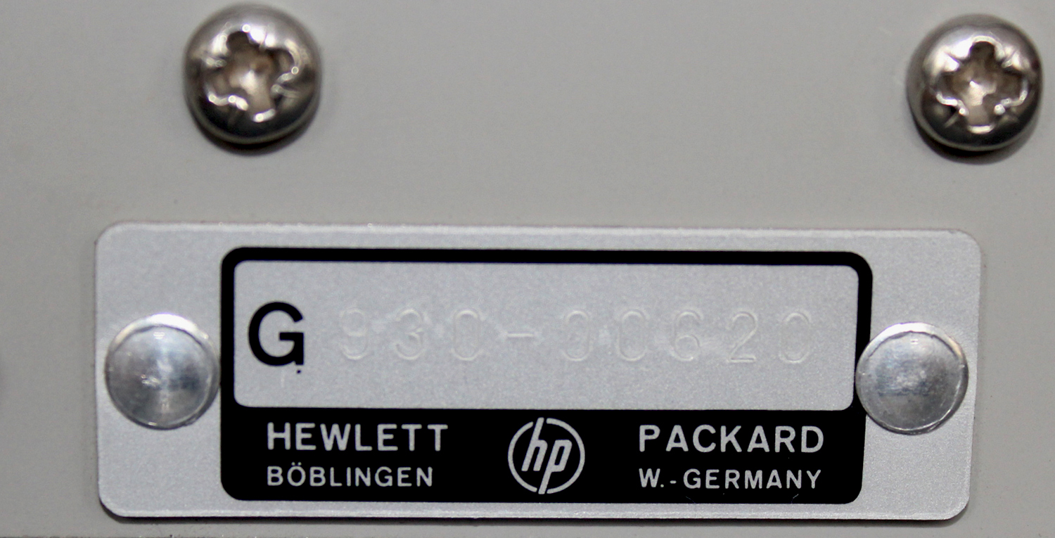
 Distortion Analyzer Hewlett Packard 332A matr. N° 930 – 96620. Prima parte.
Nell’inventario particolare del Laboratorio di Elettronica al n° D 4826, in data ottobre 1970, si legge: “Distortion Analyzer S/N 620 mod. 332A”.
Nell’ HEWLETT·PACKARD Journal VOL. 17 NO. 8 APRIL 1966 vi è addirittura la presentazione del modello 334A che nell’amplificatore di eliminazione della tensione a frequenza fondamentale (rejection) ha il ponte di Wien, come questo mod. 332A e come l’esemplare -hp- 330B che si può vedere in questo sito nella sezione Radiotecnica.
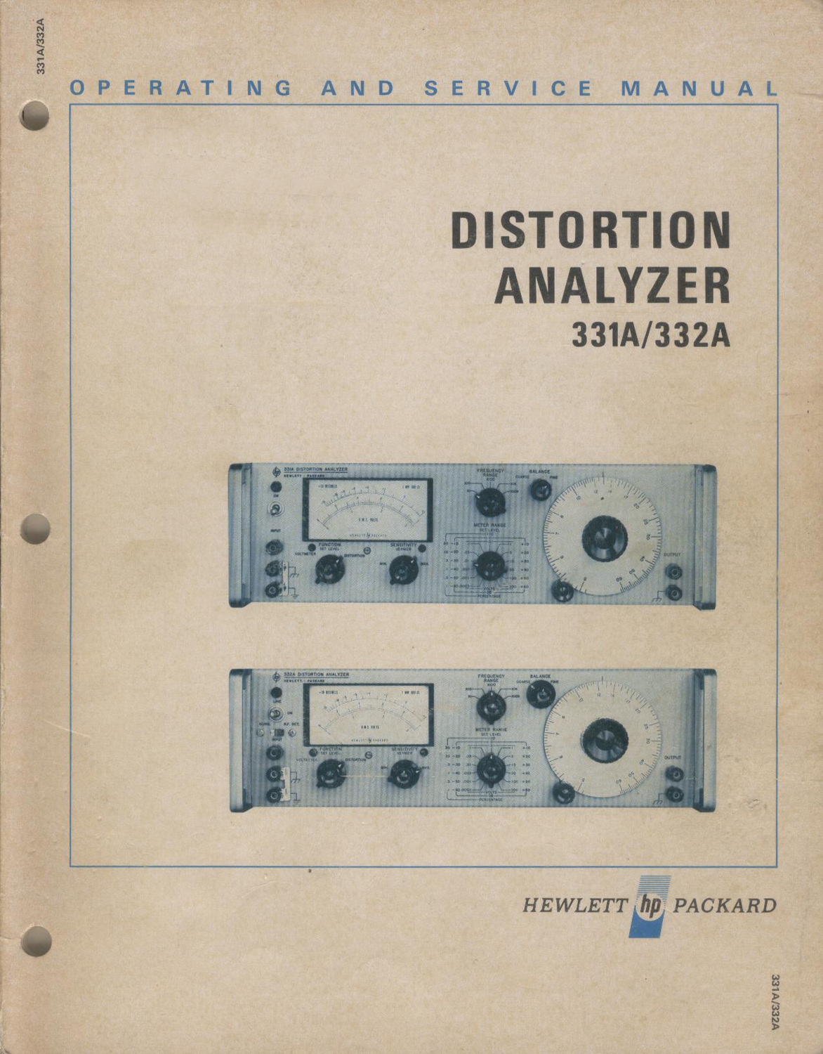
Il manuale di istruzioni, da cui sono tratte le seguenti figure, OPERATING AND SERVICE MANUAL DISTORTION ANALYZER 331A/332A HEWLETT hp PACKARD Printed JUNE 1969 è conservato presso la Sezione Elettronica.
Istruzioni quasi identiche si possono trovare ad esempio all’indirizzo: https://www.artisantg.com/info/ATGx6v9r.pdf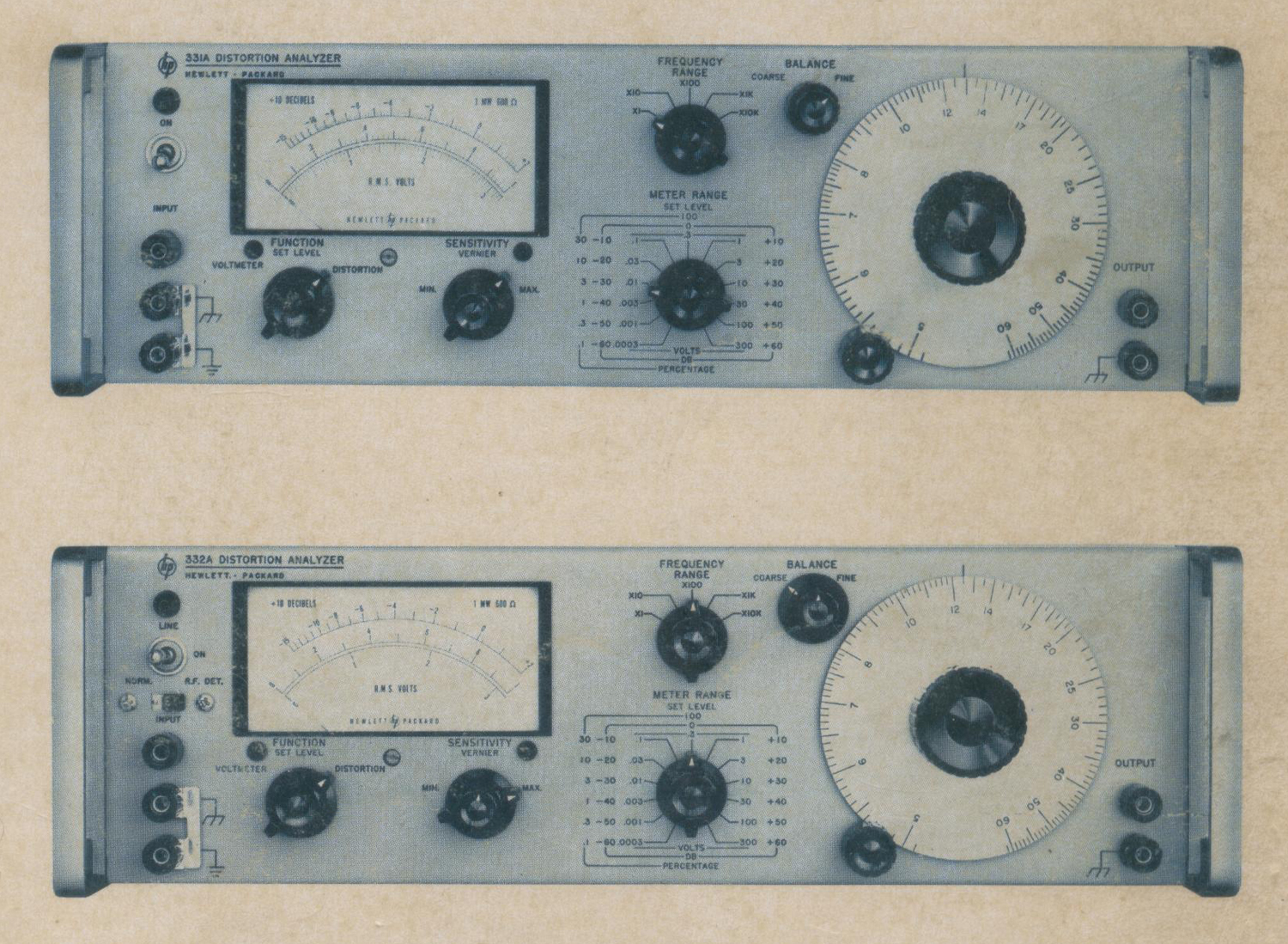
 §§§
§§§
«SECTION I
GENERAL INFORMATION
1-1. DESCRIPTION.
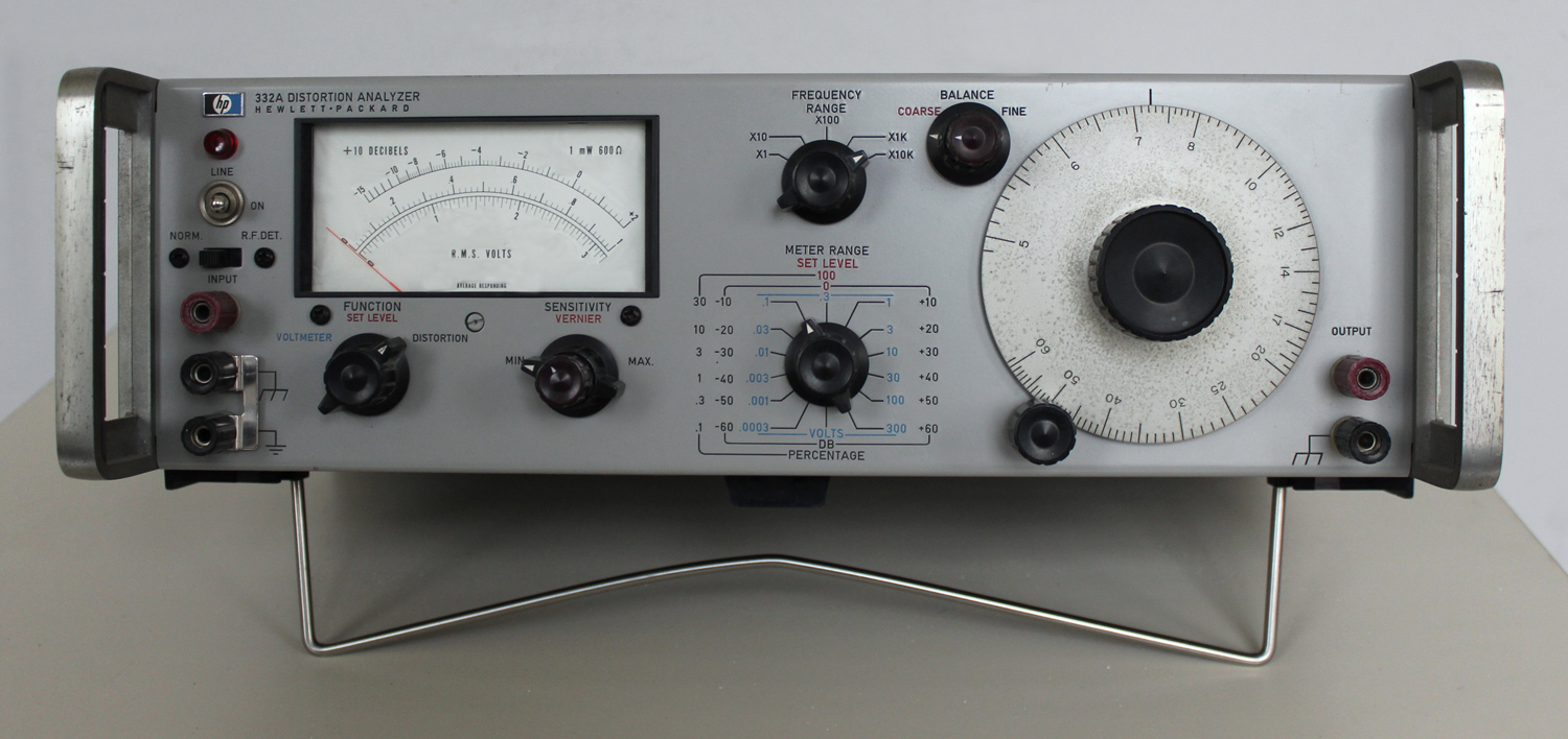
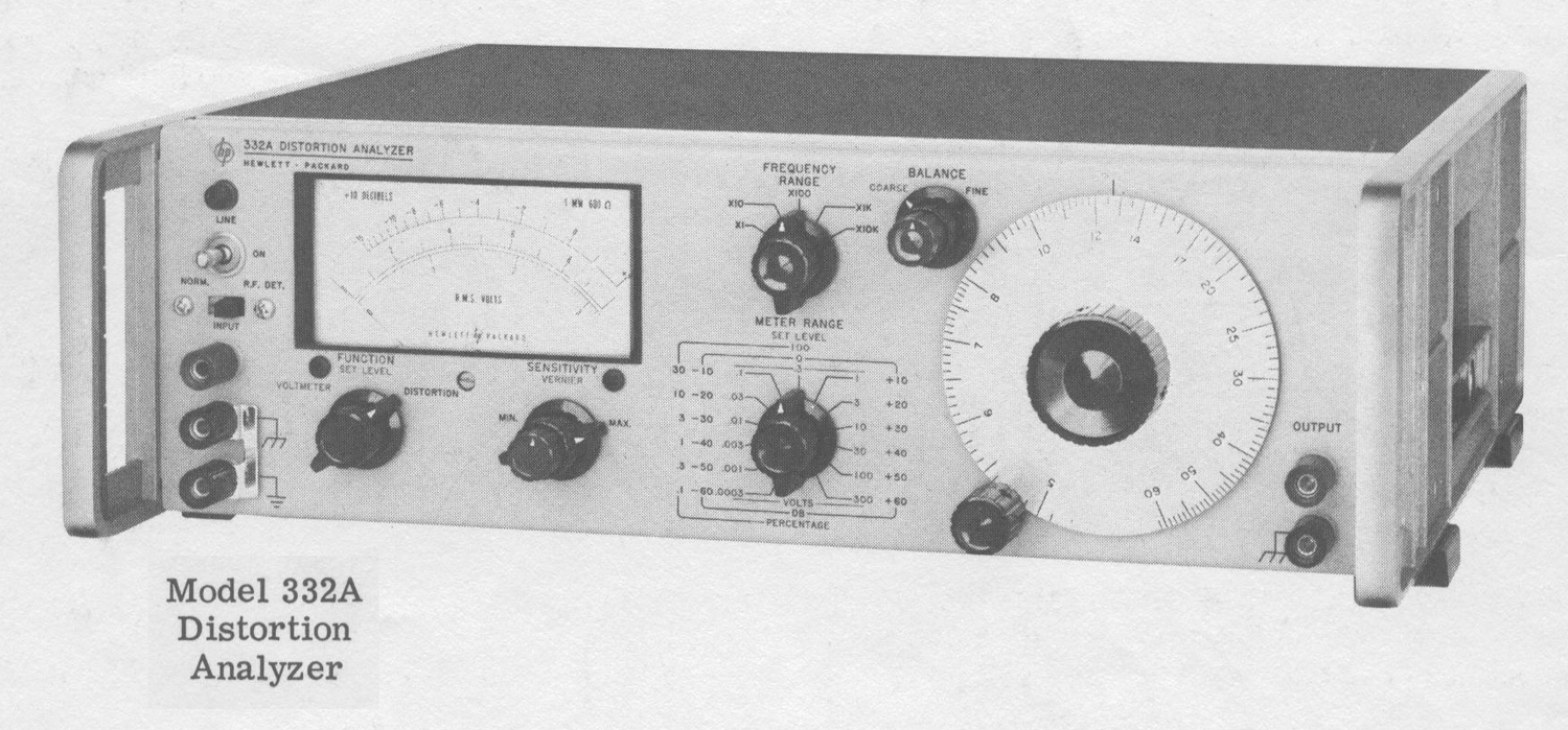
1-2. The Hewlett-Packard Models 331A and 332A Distortion Analyzers are solid state instruments for measuring distortion and ac voltages. The Model 332A includes a high impedance AM detector which operates from 550 kHz to greater than 65 MHz.
1-3. Distortion levels of 0. 1% to 100% full scale are measured in seven ranges for any fundamental frequency from 5 Hz to 600 kHz; harmonics are indicated up to 3 MHz.
The high sensitivity of these instruments requires only 0.3 V rms for the 100% set level reference. An output is provided at the OUTPUT connectors for monitoring the distortion with an oscilloscope, a true rms voltmeter, or a wave analyzer. The instruments are cabable {capable??} of a dc isolation voltage of 400 volts above chassis ground.
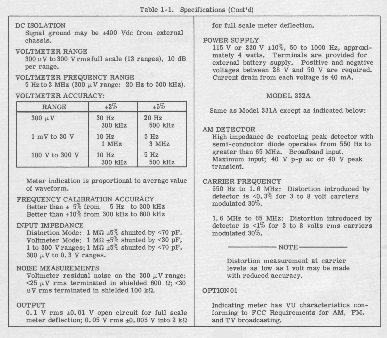
1-4. The transistorized voltmeter contained in the Model 331A and 332A can be used separately for general purpose voltage and gain measurements. The voltmeter has a frequency range of 5 Hz to 3 MHz (20 Hz to 500 kHz for 300 μV range) and a voltage range of 300 μV to 300 V rms full scale.
1-5. The AM detector included in the Model 332A is a broadband dc restoring peak detector consisting of a semiconductor diode and filter circuit. AM distortion levels as low as 0.3% can measured on a 3 V to 8 V rms carrier modulated 30% in the standard broadcast band, and lower than 1% distortion can be measured at the same level of the carrier up to 65 MHz.
1-6. ACCESSORY FEATURES.
1-7. The accessory available with the 331A and 332A Distortion Analyzers is a voltage divider probe, -hp- Model No. 10001A. The features of the probe are:
1. 10 megohm shunted by 10 pF.
2. 10:1 attenuation dc-to 30 MHz bandwidth.
3. 2% division accuracy.
4. 600 v peak input.
5. 5 nsec rise-time.
1-8. OPTION.
1-9. Option 01 is a standard -hp- Model 331A or 332A with a special meter and meter amplifier, compensated to permit response to VU (volume units) characteristics.
1-10. INSTRUMENT IDENTIFICATION.
1-11. Hewlett-Packard instruments are identified by two-section eight- digit serial number (000-00000).
If the first three digits of the serial number on your instrument do not agree with those on the title page of this manual, change sheets supplied with the manual will define differences between your instrument and the 331A and 332A described in this manual.
1 -12. If a letter prefixes the serial number, the instrument was manufactured outside the United States.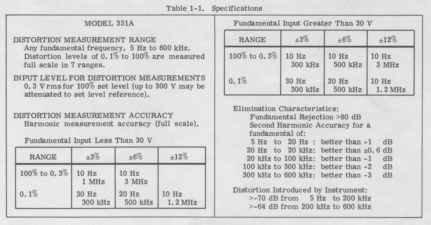
 SECTION II
INSTALLATION
2-1. INSPECTION.
2-2. This instrument was carefully inspected both mechanically and electrically before shipment. It should be physically free of mars or scratches and in perfect electrical order upon receipt. To confirm this, the instrument should be inspected for physical damage in transit. Also check for supplied accessories, and test the electrical performance of the instrument using the procedure outlined in Section V. If there is damage or deficiency, see the warranty on the inside front cover of this manual.
2-3. POWER REQUIREMENTS.
2-4. The Model 331A and 332A will operate from either 115 or 230 Vac, 48 to 440 Hz. The instruments can be easily converted from 115 to 230 volt operation by changing the position of the slide switch, located on rear panel, so that the designation appearing on the switch matches the nominal voltage of the power source. A 1/16 ampere, slow-blow fuse is used for 115 V operation; a 1/32 ampere slow-blow fuse is used for 230 V operation. The instruments can be battery operated by connecting two 28 to 50 V batteries (rated at 40 milliamperes) to the battery terminals on the rear panel.
2-5. THREE-CONDUCTOR POWER CABLE.
2-6. To protect operating personnel, the National Electrical Manufacturers’ Association (NEMA) recommends that the instrument panel and cabinet be grounded. This instrument is equipped with a three-conductor power cable which, when plugged into an appropriate receptacle, grounds the instrument. The offset pin on the power cable three-prong connector is the ground wire.
2-7. To preserve the protection feature when operating the instrument from a two-contact outlet, use a three-prong adapter and connect the green pigtail on the adapter to ground.
2-8. INSTALLATION.
2-9. The 331A and 332A are fully transistorized; therefore, no special cooling is required. However, the instruments should not be operated where the ambient temperature exceeds 55°C (131°F)».
§§§
Le parti: 2.10; 2.11 e 2.12 sono state omesse.
Per vedere le altre tre parti scrivere “332A” su Cerca.
Foto di Claudio Profumieri, elaborazioni e ricerche di Fabio Panfili.
Per ingrandire le immagini cliccare su di esse col tasto destro del mouse e scegliere tra le opzioni.