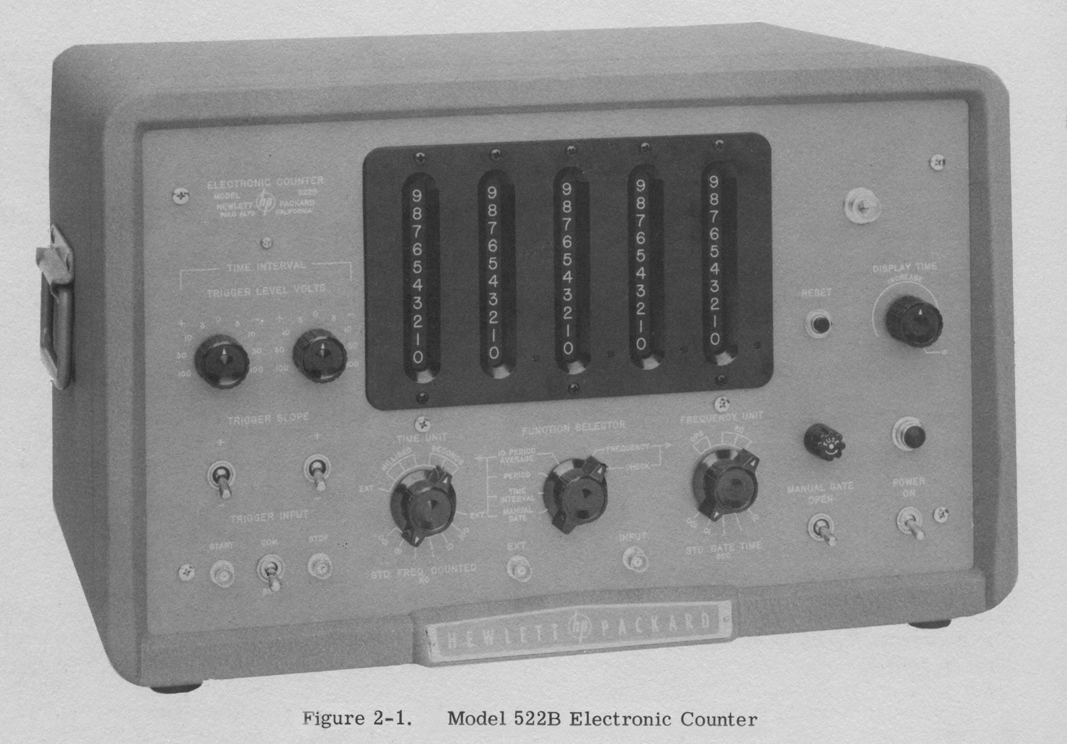
 Electronic Counter Hewlett-Packard Model 522B Serial 2733, Palo Alto California.
Importato da: Dott. Ing. Mario Vianello – Milano. Prima parte.
Nell’inventario D del 1956, in data 7 giugno 1960, al n° 1800 si legge: “Fondazione Carlo e Giuseppe Piaggio – Genova. Contatore elettronico HP mod. 522. Destinazione Radiotecnica”.
All’indirizzo:
https://www.hpl.hp.com/hpjournal/pdfs/IssuePDFs/1952-11.pdf
si può trovare l’ Hewlett-Packard Journal Vol. 4 No. 3 del novembre 1952.
Il cui titolo è: “A New 100 KC Counter for Use in Electronics and Industry”.
Noi abbiamo preferito riportare una parte del manuale di istruzioni poiché le figure, opportunamente elaborate, sono meglio definite.
Abbiamo diviso il testo in due parti a causa della sua lunghezza e del numero di foto e figure.
Abbiamo deciso inoltre di omettere il capitolo “Maintenance”, ma ne abbiamo riportato le figure.
 §§§
§§§
«SPECIFICATIONS
Measures:
Frequency
Period
Time interval
Ratio
Total Events
Registration: Five places. Output pulse available to actuate trigger circuit for mechanical register providing increased count capacity.
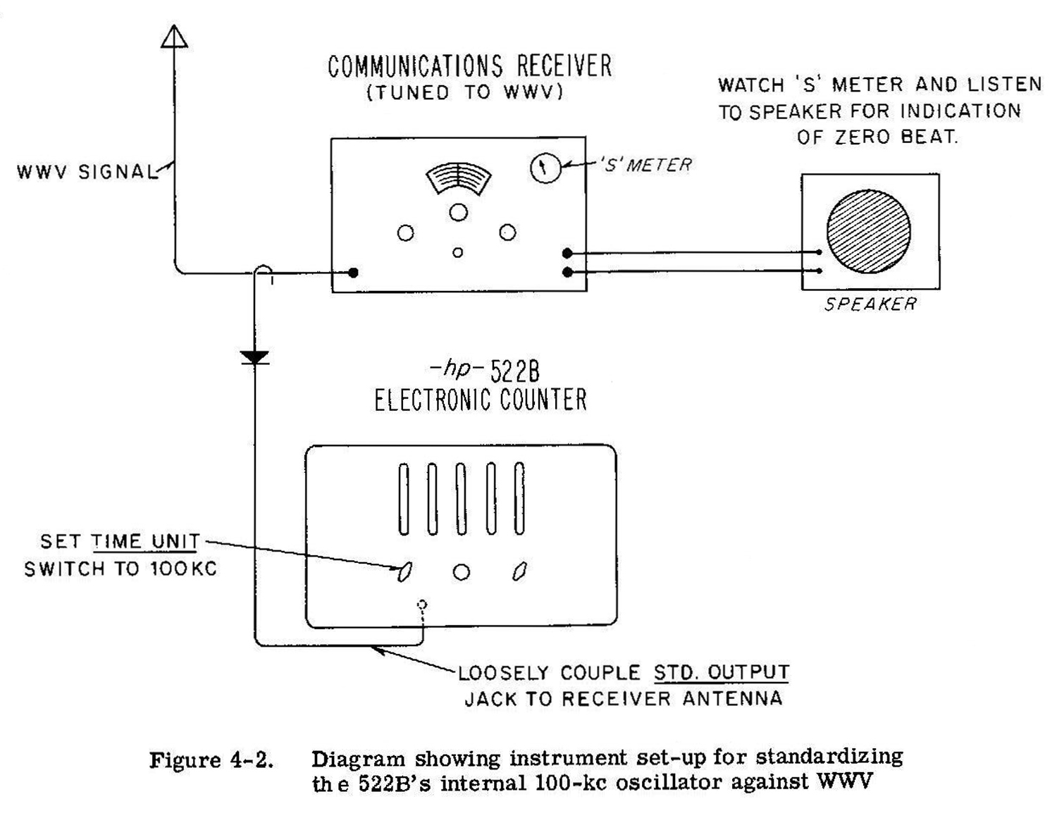
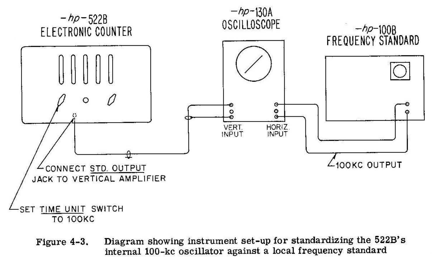
Stability: Within 10 parts per million per week. Can be standardized with standard frequency transmission from WWV.
Answer Display Time: Variable from 0. 1 to 10 seconds. Display can be held indefinitely if desired.
Check: Panel control provides automatic count of 100 kc to assure accuracy of gate and proper operation of counters.
FREQUEN CY MEASUREMENT
Range: 10 cycles/sec. 120 kc. Extendable to 220 kc by replacing units AC-4A DECADE with an hp Model AC-4B DECADE.
Accuracy: ±1 count, ± stability (see above).
Input Sensitivity: . 2 volt rms minimum. Direct coupled input. (. 5 volt rms required with AC-4B above 120 kc.)
Input Impedance: Approximately 1 megohm shunted by 50 μμf.
Gate Time: 0.001, 0.01, 0.1, 1. 0 and 10 seconds. May be extended to any multiple of l or 10 seconds by manual gate toggle switch. Panel neon lamp indicates when gate is open.
Reads In: Cps or kc. Lighted decimal point automatically positioned.
PERIOD MEASUREMENT
Range: .00001 cps to 10 kc. Output pulse is available to actuate trigger circuit for mechanical register to extend range to lower frequency.
Accuracy: ± count, ± 3%, ±stability (see Frequency Measurement) for measurement of one period. Accuracy for more than one period is ± 3% divided by number of periods ± stability. (This applies to a1 volt rms input signal. Accuracy increases with greater input signal levels.)
Input Requirements: . 2 volt rms minimum. Direct coupled input.
Input Impedance: Approximately 1 megaohm shunted by 50 μμf.
Measurement Period: One or ten cycles of unknown frequency. May be extended to any number of cycles of unknown frequency by manual control. This is limited to frequencies below 50 or 60 cycles/sec.
Standard Frequency Counted: 1, 10, 100 cps; 1, 10, 100 kc. External frequencies can also be used.
Reads In: Seconds or milliseconds. Lighted decimal point automatically positioned.
TIME INTERVAL MEASUREMENT
Range: 10 microseconds to 100, 000 seconds (27. 8 hrs.)
Accuracy: ± 1/std. frequency, ± stability (see Frequency Measurement.)
Input Impedance: Approximately 250, 000 ohms shunted by 50 μμf.
Input Requirements: 1 volt peak minimum. Direct coupled input.
Start and Stop Inputs: Independent or common channels.
Trigger Slope: Positive or negative on either channel.
Trigger Amplitude: Continuously adjustable on both channels from -100 to +100 volts .
Standard Frequency Counted: 1, 10, 100 cps; 1, 10, 100 kc. External frequencies can also be used.
Reads In: Seconds or milliseconds. Lighted decimal point automatically positioned.
GENERAL
Power Supply: 115/230 volt, 50-60 cps, 260 watts.
Size: Cabinet Mount: 20-3/4 i.nch wide, 12-1/2 inch high, 14-1/2 inch deep.
Rack Mount: 19 inch wide, 10-1/2 inch high, 14-1/2 inch deep.
Weight: Cabinet Mount: 45 lbs.; approx. shipping weight, 90 lbs.
Rack Mount: 40 lbs.; approx. shipping weight, 80 lbs.
Features:
a) Operates with -hp— 508 Tachometer Generators for tachometry.
b) Operates with -hp— 520A for high speed nuclear scaling, or directly for peak rates up to 100, 000 per second.
c) Measures frequency ratios.
d) Operates as electronic stop watch with manual start, stop and reset.
e) Operates as a secondary frequency standard providing precise rectangular output voltages at 1, 10, 100 cps; 1 and 10 kc and a 100 kc sine wave. Amplitude, approximately 1 volt peak.
Accessories Provided: 2 – AC-16D cable assemblies, 44 inches RG-58/U terminated one end with UG-88/U Type BNC connector.
Accessories Available: AC-4B Decade Divider Unit which increases top frequency range to 220 kc.
AC -16K Cable Assembly, 48 inches RG-58/U terminated both ends with UG-88/U Type BNC connectors.
AC-17 End Frames with handles for bench use of rack mount unit. -hp- Model 508 Tachometer Generators. Convert -hp- Model 522B into tachometer indicator with direct mechanical connection to equipment under test.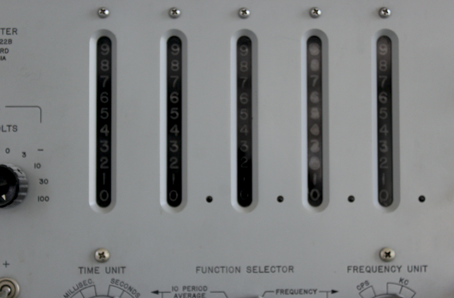
SECTION I
GENERAL DESCRIPTION
1.1 INTRODUCTION
The Model 522B Electronic Counter is an accurate and easy to use instrument for frequency, period, and time interval measurements. Frequency measurements from 10 cycles/sec. to 120 kc* and period measurements from .00001 cycles/sec. to 10 kc may be made with this instrument. The instrument and display of the counted value may be preselected for automatic operation or set to any desired interval by manual control. This counter is suitable for standard audio-frequency oscillators to very high accuracy and facilitates response measurements of sharply resonant networks. The frequency stability of oscillators as a function of time may be measured directly with this instrument. Transducers which provide an output frequency related to the magnitude of such physical constants as
___________________________________________
* The 522B can be quickly and easily converted to measure frequencies as high as 220 kc by simply replacing the “UNITS” AC-4A Decade Counter unit with an -hp- Model AC-4B Decade Counter unit. The decade units plug in and no special adjustments need be made. weight, pressure, temperature, small distances and force may be used with the electronic counter for increased accuracy and quickness of reading. Exceptionally accurate tachometer measurements are obtained by connecting a transducer, which translates rotation into electrical impulses, to the input of the counter.
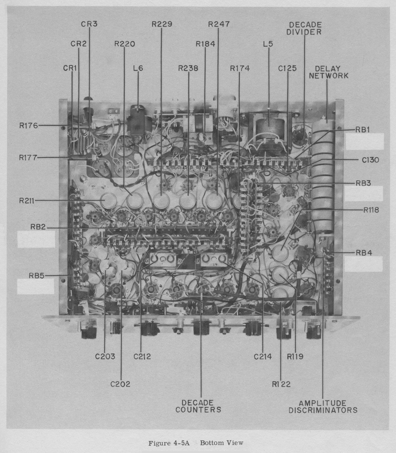
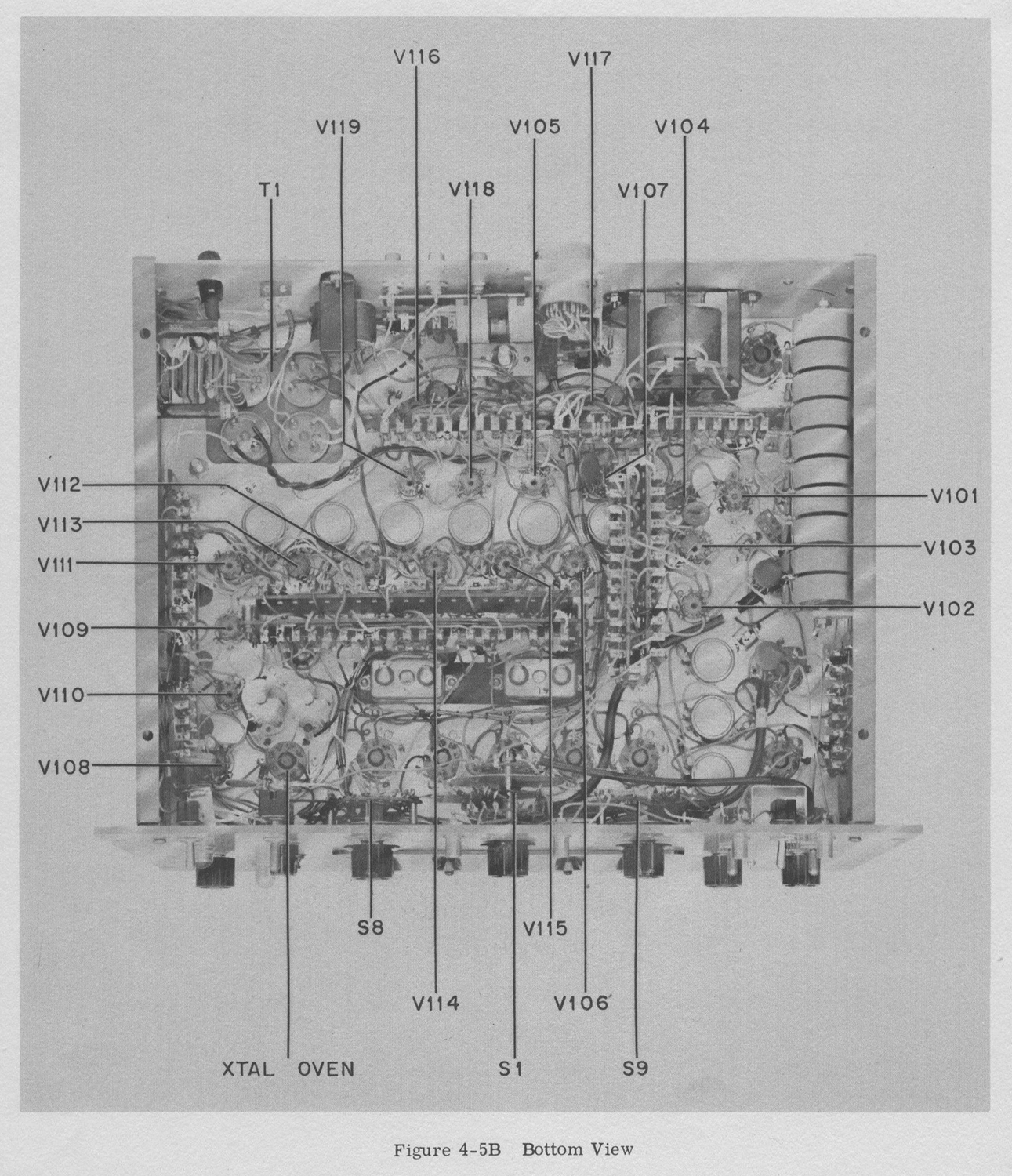
1-2 INSPECTION [Omissis]
SECTION II
OPERATING INSTRUCTIONS
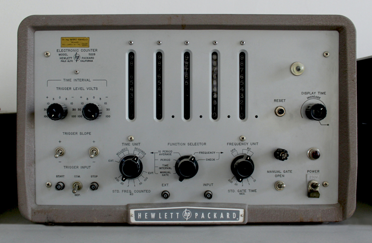
2-1 CONTROLS AND TERMINALS
CONNECTORS
All cable receptacles on the instrument are BNC type UG-625A/U. Connector UG-88/U Should be used with these receptacles.
TIME INTERVAL
The designations and functions of the various controls and terminals that comprise the time interval section of the instrument are listed below.
TRIGGER INPUT
START – This connector is the input terminal for the start channel during TIME INTERVAL measurement. The TRIGGER SLOPE switch and TRIGGER LEVEL VOLTS control above the connector are part of the START input circuit
STOP – This connector is the input terminal for the stop channel during TIME INTERVAL measurement. The TRIGGER SLOPE switch and TRIGGER LEVEL VOLTS control above the connector are part of the STOP input circuit.
COMM. -SEP. – The START and STOP connectors are connected together when this toggle switch is in the COM. (common) position. Under this condition both the start and stop trigger voltage may be applied to the-instrument through either the START or STOP connectors. In the SEP. (separate) switch position there is no connection between the START and STOP connectors and the start and stop trigger voltages must be applied to their respective connectors.
TRIGGER SLOPE
In the positive position of the switches, the rising portion of the wave controls the time interval. In the negative position the falling portion of the wave controls the time interval. The left hand switch is for the start channel. The right hand switch is for the stop channel.
TRIGGER LEVEL VOLTS
These controls establish the triggering level of the start and stop channels.
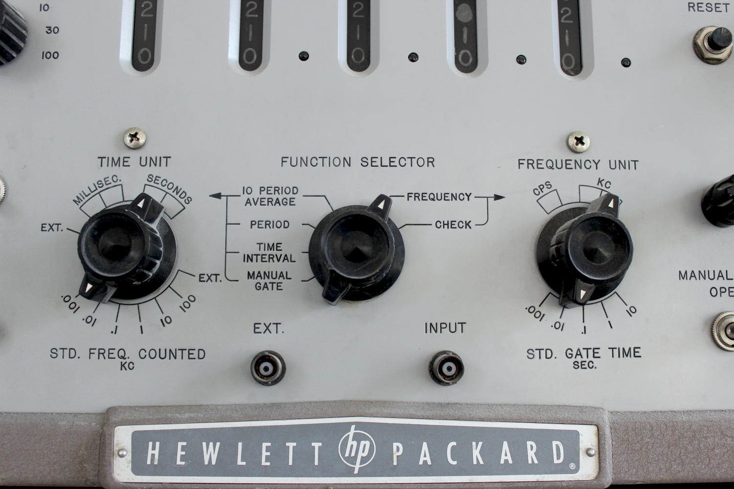
TIME UNIT
The TIME UNIT switch selects the units of time for the time measurements shown on the left side of the FUNCTION SELECTOR switch (10 PERIOD AVERAGE to MANUAL GATE). Indications are in seconds or milliseconds with decimal point indicated. The designations below the switch are the counted frequencies, in kilocycles, obtainable from the standard time base. The switch position designated EXT. is for an externally counted frequency. In this position the EXT. connector is substituted in place of the internal standard time base. No time unit is specified when the EXT. position is used and no decimal point appears.
FUNCTION SELECTOR
This switch sets up the various circuits to perform the functions shown by the switch position designations. The designations on the left side of the FUNCTION SELECTOR switch pertain to time measurements while those on the right side are for frequency measurements. The switch position designations and their functions are as follows:
10 PERIOD AVERAGE – Measures the incoming waveform for a period of ten cycles and displays the period of one cycle. The units of measurement of time are dependent on the setting of the TIME UNIT switch.
PERIOD – Measures the incoming waveform for a period of one cycle and displays this period. The units of measurement of time are dependent on the setting of the TIME UNIT switch.
TIME INTERVAL – Measures and displays the time interval between the start and stop trigger voltages. The units of measurement of the time interval, are dependent on the setting of the TIME UNIT switch.
MANUAL GATE – This function is used for long-term counting where the gate is controlled by means of the MANUAL GATE switch. In this position the instrument may be used as an electronic stop watch.
FREQUENCY – Counts and displays frequency of incoming waveforms. Counting time depends on the setting of the FREQUENCY UNIT switch.
CHECK – The instrument is self-checking when the switch is in the CHECK position.
FREQUENCY UNIT
This switch determines the length of time in seconds that the gate is open during frequency measurements. The frequency units are indicated above the knob.
DISPLAY TIME
This control varies the time that the count is displayed. The minimum display time obtainable is .1 second or the gate time, whichever is larger. The maximum time is 10 seconds unless the control is switched to ∞ in which case the count is displayed indefinitely. When the control is in the ∞ position, the count is displayed until the counting cycle is started again by depressing the RESET button.
RESET
When this button is depressed, the counters are returned to zero and a new counting cycle is ready to start.
FUSE
The fuseholder, located on the control panel, contains a 3.2 ampere cartridge fuse. For 230 volt operation the fuse should have a rating of 1.6 amperes. Replacement fuses must be of the “Slo-Blo” type as specified in the Table of Replaceable Parts in this instruction manual.
POWER ON
This switch controls all the power supplied to the instrument.
MANUAL GATE
This switch opens and closes the gate when the FUNCTION SELECTOR switch is in the MANUAL GATE position. In other positions of the function switch, the MANUAL GATE switch in the OPEN position prevents the stop pulse from closing the gate.
INPUT
This connector is the input terminal for frequency and period measurements. During TIME INTERVAL, MANUAL GATE, and CHECK functions this connector is grounded through the input coupling network.
EXT.
This connector is the input terminal for any external time unit and is connected in place of the internal time unit when the TIME UNIT switch is in the EXT. position.
POWER CABLE
The three-conductor power cable on the 522B is terminated in a polarized three-prong male connector recommended by the National Electric Manufacturers’ Association. The third contact is an offset round pin, added to a standard two-blade a-c plug, which grounds the instrument chassis when used with the appropriate receptacle. To use this NEMA plug in a standard two-contact outlet, it is recommended that instead of breaking off the ground terminal, a 2-prong to 3-prong adapter be used. The ground connection emerges from the adapter as a short lead which should be connected to ground for the protection of operating personnel.
COUNTER OUTPUT
The output of the last counter is available at this terminal, located on the back of the chassis.
PHOTOTUBE VOLTAGE
A +90 volt polarizing voltage is available at the rear of the instrument. It has an internal impedance of approximately 100,000 ohms.
STD. OUTPUT
Internally-generated standard frequencies are available at this connector. These frequencies are the STD. FREQUENCY COUNTED and are selected by means of the TIME UNIT switch. 2-2 OPERATION
It should be kept in mind while using the Model 522B that this instrument measures, basically, frequency or time. There are two basic time measurements that can be performed, period and time interval. Period measures the time between two consecutive points on a single waveform. Time interval measures the time between two separate waveforms. This instrument requires a warm-up period of at least 30 minutes before the specified accuracy is obtained from the crystal. Less accurate measurements may be made after a 30 second warm-up, and the sensitivity will be approximately 1/2 volt at this time. Before making any measurements with this instrument, it is desirable to check the performance of the instrument by means of the built-in checking circuit. This is done as follows:
a. Set the FUNCTION SELECTOR switch to the CHECK position and the FREQUENCY UNIT switch to 1 SEC.
b. Set the DISPLAY TIME control fully counter-clockwise.
c. If all the counters display zero at the end of the count, then the instrument is performing properly. If this count is not displayed, refer to the Maintenance section for probable causes and remedies.
The procedure for operating, the Model 522B is as follows:
NOTE: The input circuit of the 522B is direct coupled to the amplitude discriminator. Any dc voltage present at the input will affect the sensitivity of the amplitude discriminator circuit when measuring FREQUENCY or PERIOD. If dc voltage is present, an external 2 μf blocking capacitor connected in series with the INPUT jack will allow measurements to be made down to 1 cps at rated sensitivity. A larger capacitor is required for lower frequencies.
Frequency Measurement
a. Set the FUNCTION SELECTOR switch to FREQUENCY and the FREQUENCY UNIT switch to the STD. GATE TIME position that provides the desired measuring unit. MANUAL GATE switch in the closed position.
b. Connect the unknown frequency to the INPUT connector of the instrument. The input voltage must not exceed 100 volts. As this instrument is triggered whenever the input voltage passes through zero, any direct current component in the input voltage will change the triggering point.
For example, an input voltage of 5 volts which has a direct current component of 10 volts will not trigger the instrument. However, an input voltage of 15 volts with a 10 volt direct current component will trigger the instrument at the 10 volt level.
c. The MANUAL GATE switch may be used to extend the time that the gate is open so that multiples of the selected gate time may be obtained. When the MANUAL GATE switch is in the OPEN position the gate cannot close. When the switch is returned to the closed position, the gate will close at the next timing pulse. To extend the gate time, the MANUAL GATE switch is placed in the OPEN position. Just prior to the desired count time the MANUAL GATE switch should be returned to normal, and the next timing pulse will accurately close the gate.
Example: It is desired to measure a 5000 cycle/sec. wave for a time of 4 seconds. The time unit selected on the FREQUENCY UNIT switch would be 1 second. The MANUAL GATE switch may be open either before or after the count has begun but must be open before 1 second of counting time has elapsed. It must be closed between the 3rd and 4th second of counting time.
d. Adjust the DISPLAY TIME control so that the count is displayed long enough to be read conveniently. The count display will be cycles or kilocycles per second as indicated by the position of the FREQUENCY UNIT switch.
10 Period Average Measurement
a. Set the FUNCTION SELECTOR switch to the 10 PERIOD AVERAGE position and the TIME UNIT switch for the desired unit time. Connect the waveform to be measured to the INPUT terminal. The direct current component of the input waveform must be considered as it will produce the effects described in the Frequency Measurement procedure. The MANUAL GATE switch should-be in the closed position.
b. Adjust the DISPLAY TIME control for convenient reading of the count. The displayed count will be the average period of one cycle although 10 cycles were measured. The MANUAL GATE switch will function on period measurements similar to frequency measurement. However, on period measurements the time is a multiple of the input wave, for example: It is desired to measure the period of a 20 cycles/ sec. wave for 100 periods. On 10 period average the count displayed will be 50.0 milliseconds. Then for 100 periods which is 10 times 10 period average, the count should be 500.0 milliseconds. Thus the MANUAL GATE switch should be closed between the 9th and 10th ten periods which would be between 450.0 and 500.0 count. The period of the 20 cycles/sec. wave will now be 500.0 divided by 10 or 50.00 milliseconds. The accuracy has been increased by ten time over the accuracy of the ten period average.
Period Measurement
The procedure for measuring the period of one cycle is the same as for the 10 Period Average except that the FUNCTION SELECTOR switch is set at PERIOD.
Time Interval Measurement
a. Set the FUNCTION SELECTOR switch at TIME INTERVAL and the TIME UNIT switch at the desired time unit. The MANUAL GATE control must be in the closed position.
b. If the interval of time to be measured is a pulse-width, repetition rate, rise time of a sloping wave, or some other function in which both start and stop information is on a single wire, set the SEP. -COM. switch to COM. and connect the input voltage to either the START or STOP terminal. In the COM. position the two inputs are tied together. If the interval to be measured is from two separate sources – such as two phototube or two sine waves of different phase – place the SEP. -COM. switch in SEP. Connect the starting signal to the START terminal and the stop signal to the STOP terminal.
c. The TRIGGER SLOPE switches and TRIGGER LEVEL VOLTS controls are the same for both the start and stop channels. The following considerations therefore apply to both channels.
If the desired trigger point of the input waveform is rising (going in a positive direction), set the TRIGGER SLOPE switch to +. If the desired trigger point of the input waveform is falling (negative going), the TRIGGER SLOPE should be set to -.
To set the TRIGGER LEVEL VOLTS controls it is necessary to know the voltage levels of the input wave. The TRIGGER LEVEL VOLTS control is then set to the voltage value desired. Any direct current component of the signal must also be considered when setting these controls.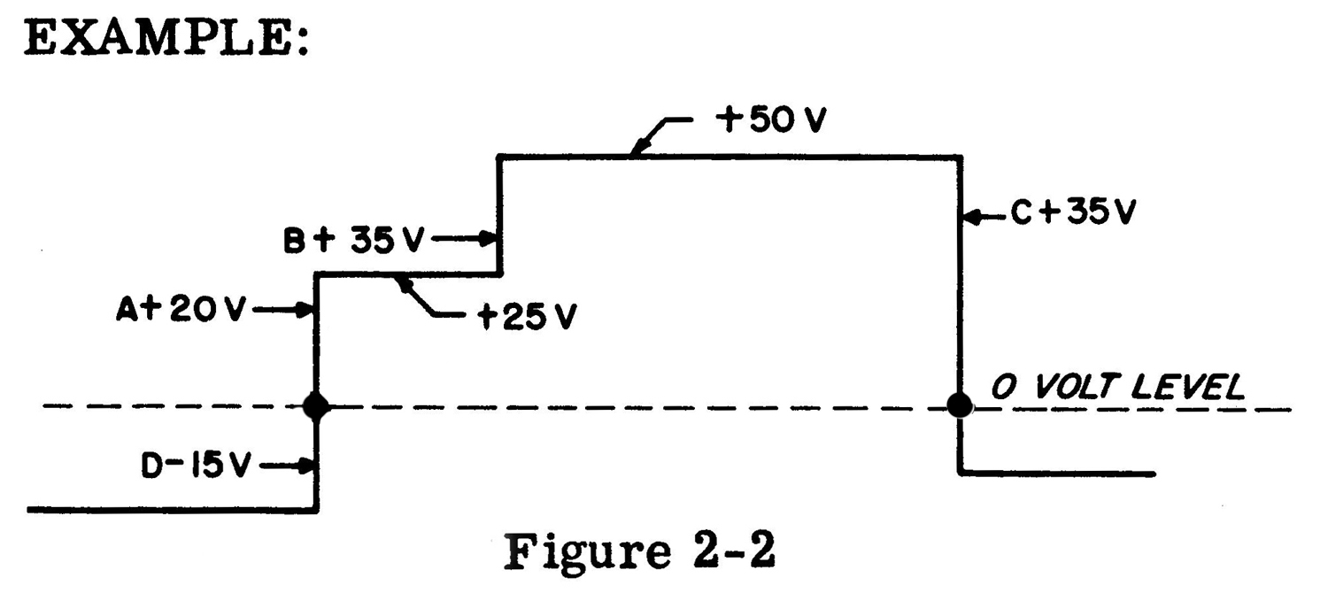 It is desired to measure the time between points A and C of Figure 2-2. Since this is a single signal, the SEP. -COM. switch should be in the COM. position. Since the voltage at point A is rising, set the start TRIGGER SLOPE switch to +. and the start TRIGGER LEVEL VOLTS control to +20. Point C is negative going and the stop TRIGGER SLOPE switch should be set to -. The stop TRIGGER LEVEL VOLTS should be set to +3 5V. Set the TIME UNIT switch to the desired unit. It will be noted that if the start TRIGGER LEVEL VOLTS control were set to +35 instead of +20, the time from points B to C would be measured. Also if the stop TRIGGER SLOPE switch were changed to + instead of -, the time between points A and B would be measured. In measuring the time between A and C the start TRIGGER LEVEL VOLTS control could be set at point D (-15V) which will give the same time.
External Input
In both period and time interval measurements, it may be desirable to have a count in some unit other than or in terms of some other frequency. For instance, the period of a 2 cycle wave could be in terms of some other wave, say 3600 cycles. This gives the ratio of the two frequencies which would be 1800 to 1. The procedure for using the external input is as follows:
a.Set the FUNCTION SELECTOR switch to the 10 PERIOD AVERAGE, PERIOD, or TIME INTERVAL position.
b. Set the TIME UNIT switch to EXT. and connect the external frequency to the EXT. terminal.
c. Connect the source to be measured to the INPUT terminal or the START and STOP terminals (Time Interval) whichever function is being used.
d. The displayed count is obtained in units of the external signal applied to the instrument. When the TIME UNIT switch is in the EXT. position, the decimal points are not illuminated.
Manual Gate
a. Set the FUNCTION SELECTOR switch to MANUAL GATE and the TIME UNIT switch to the EXT. position.
b. Set the MANUAL GATE switch to the closed position. Connect the source to be measured to the EXT. terminal.
c. To start the count, throw the switch to the OPEN position. At the end of the desired elapsed time change the switch back to the closed position. Read the displayed count, push the RESET button and the instrument is ready to count again. The time, during which the gate is open, must be measured by some device outside of the instrument.
In this operation the MANUAL GATE switch actually opens and closes the gate at the instant the switch is operated and not at the next timing pulse as in all of the previous operations. The MANUAL GATE switch may be opened and closed as often as desired and no resetting will occur. Resetting must be done manually by the RESET button, and may be done at any time.
2-3 ACCURACY
Frequency Measurements
The basic counter accuracy is determined by two factors. One factor is the stability of the 100 kc crystal standard in the time base, which is 10 parts per million or .001 percent per week. A second factor is the inherent error of ±1 count present in all counters of this type. This error is due to phasing between the timing pulse that operates the electronic gate and the pulses that pass through the gate to the counters. The chart in Figure 2-3 shows the errors to be expected for frequency or period measurements. For example, if a frequency of 10 kc is being measured with a 10 second gate time, there will be a total of 100,000 counts. An error of +1 count is .001 percent accuracy. If 20 kc is measured for 10 seconds, a total of 200,000 counts, ±1 count is .0005 percent. However, the accuracy (.001 percent) of the crystal standard also must be taken into consideration. The overall accuracy for frequency measurements then is as follows:
Maximum Possible error (percent) = ± 1 count ± accuracy of standard.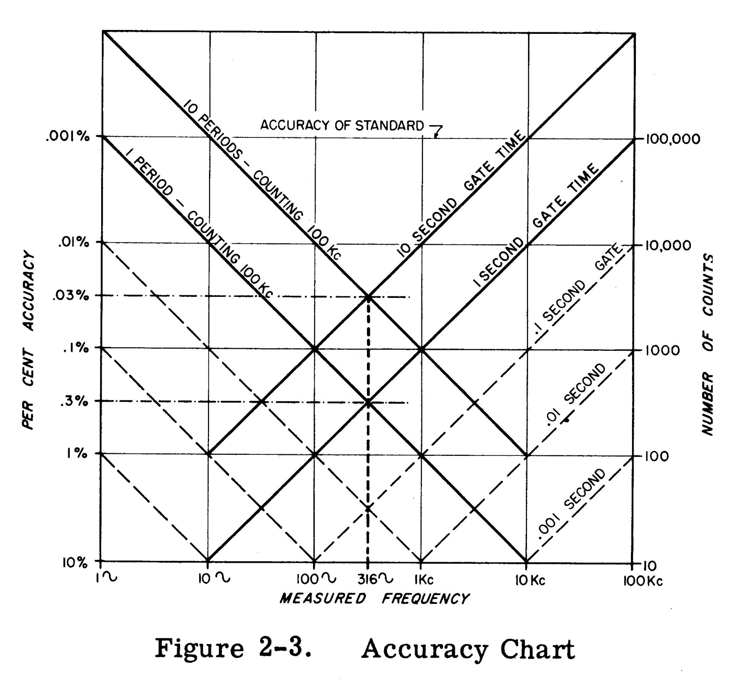
The maximum possible error for the 20 kc example is ± .0005 percent ± .001 percent, the two being additive in the worst case. Therefore, the greatest possible error would be .0015 percent. Due to the possible error of ± 1 count, as the measured frequency becomes lower, the percentage error becomes higher. For a 10-cycle wave on a 1-second gate the accuracy is ±10 percent. For low frequencies the period of the waveform should he measured.
Period Measurements
On both PERIOD and 10 PERIOD AVERAGE the TIME UNIT switch will select the counted frequencies which range from 100 kc to 1 cps. Referring again to the chart of Figure 2-3, it will be noted that the greatest accuracy of period measurement is obtained on 10 period average when counting 100 kc. This of course gives the greatest total number of counts. It should be stressed at this point that the greatest accuracy for period measurement is obtained from waveforms having a sharp rise time or high slope as they pass through the zero axis. Square waves or pulses usually meet this requirement. On a sine wave or other low slope waveform the accuracy of period measurement is limited by the ability of the input circuits to trigger at the same point on consecutive cycles. The period accuracy for a sine wave is as follows: Max Error in percent = (23 × Peak noise voltage) / (No. of Periods × RMS signal voltage). Both internal and external noise voltages contribute to the errors. The internal noise voltage is approximately 5 mv peak. Therefore, during PERIOD measurements an accuracy of .3 percent can be expected for a 1 volt rms sine wave with 10 mv noise. This accuracy can be improved by greater amplitude of input signal or by measuring a greater number of periods. Thus for a 1 volt rms sine wave on 10 PERIOD AVERAGE the accuracy expected would be .03 percent. On 10 PERIOD AVERAGE with a 10 volt rms signal containing 1 percent noise the maximum possible error would then be .003 percent. The line marked 1 Period – Counting 100 kc on Figure 2-3 is also for 10 Period – Counting 10 kc. Similarly the next lower line (dotted line running from 1 kc to .01 percent) is 1 Period – Counting 10 kc and also 10 Period – Counting 1 kc. The next line is 1 Period – Counting 1 kc and 10 Period – Counting 100 cps. This chart could be extended down and to the left to a measured frequency of .0001 cps. It will be noted that the period curves and the frequency curves cross at 316 cycles measured frequency. Thus, for frequencies above 316 cycles direct measurement of frequency gives the greatest accuracy. Below 3l6 cycles period measurements should be used.
Time Interval Measurements
There are three factors contributing to the accuracy of time interval measurements.
a. The stability of the 100 kc standard which is ± .001 percent.
b. The ambiguity of ±1 count.
c. A time error due to input slope.
Where the START and STOP inputs are sloping waves, the largest error is usually due to the inability of the input circuits to trigger consistently at the same point. With a setting of zero volts trigger level, the overall accuracy should be:
Maximum error ± .001 percent ± period of counted freq. ± sum of times required for start and stop voltages to change 1 volt.
As the trigger level is increased either positive or negative, attenuation of input signal is introduced. The slope error increases as attenuation is introduced. At a trigger level of 100 volts the attenuation is approximately 5 to 1, at 30 volts about 2.7 to 1, and at 10 volts about 1.6 to 1.
Example:
A measurement of time interval is being made where the start voltage has a rise of 1 volt in 120 μsec. and the stop voltage has a rise of l volt in 5 μsec. at the trigger point.
If the time measured is about 500 milliseconds when counting 100 kc, the largest error would be
± .001 percent of 500 rms = ± 5.0 μsec.
± period of 100 kc = ± 10 μsec.
± (120 μsec. + 5 μsec.) = ± 125 μsec. Maximum possible error = 140 μsec.
There is a maximum error of 140 μsec. out of the
500.00 milliseconds measured, this is a maximum
error of .028 percent.»
§§§
Il testo prosegue nella seconda parte; per consultarla scrivere “522B” su Cerca.
Foto di Claudio Profumieri, elaborazioni e ricerche di Fabio Panfili.
Per ingrandire le immagini cliccare su di esse col tasto destro del mouse e scegliere tra le opzioni.