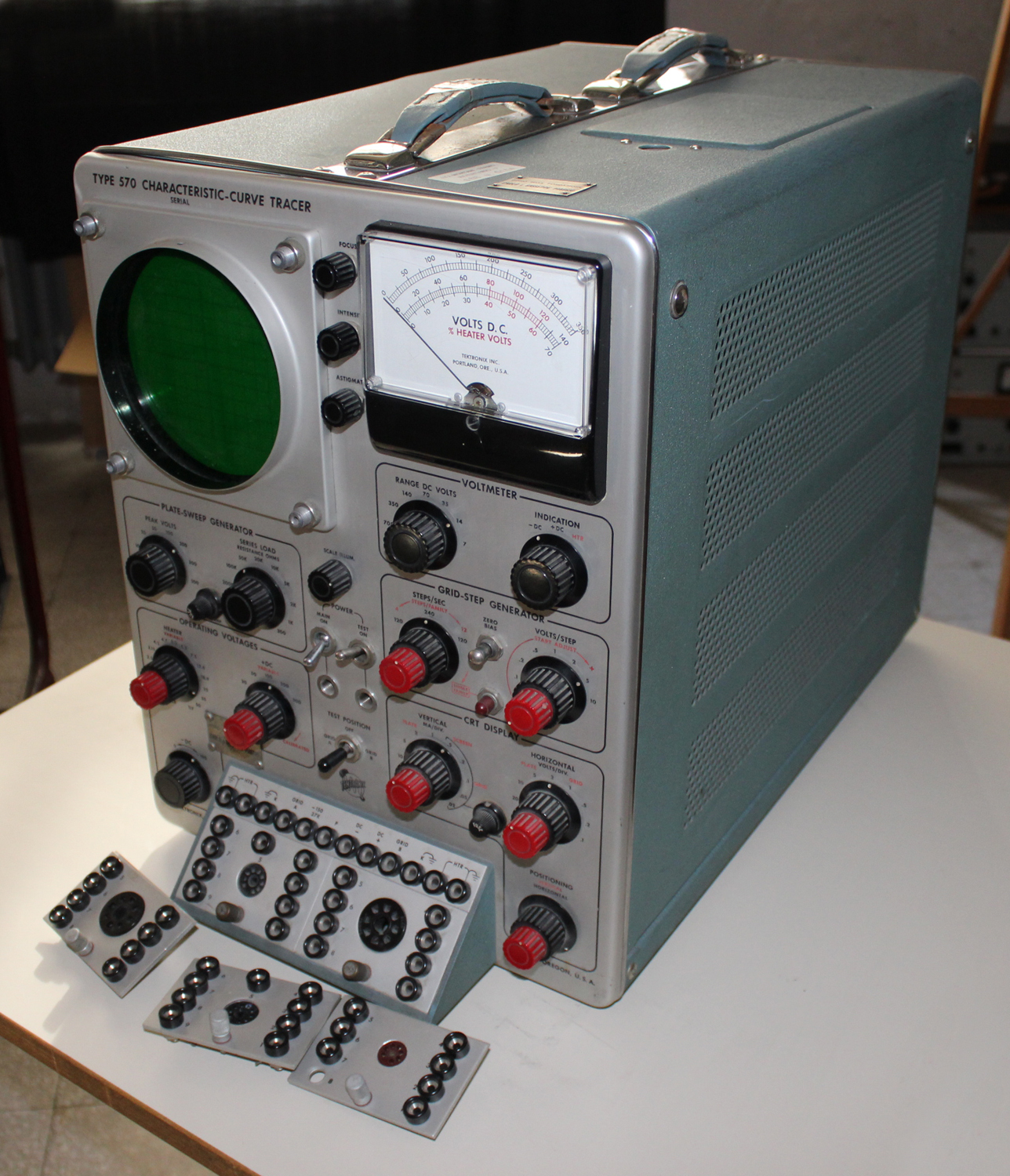
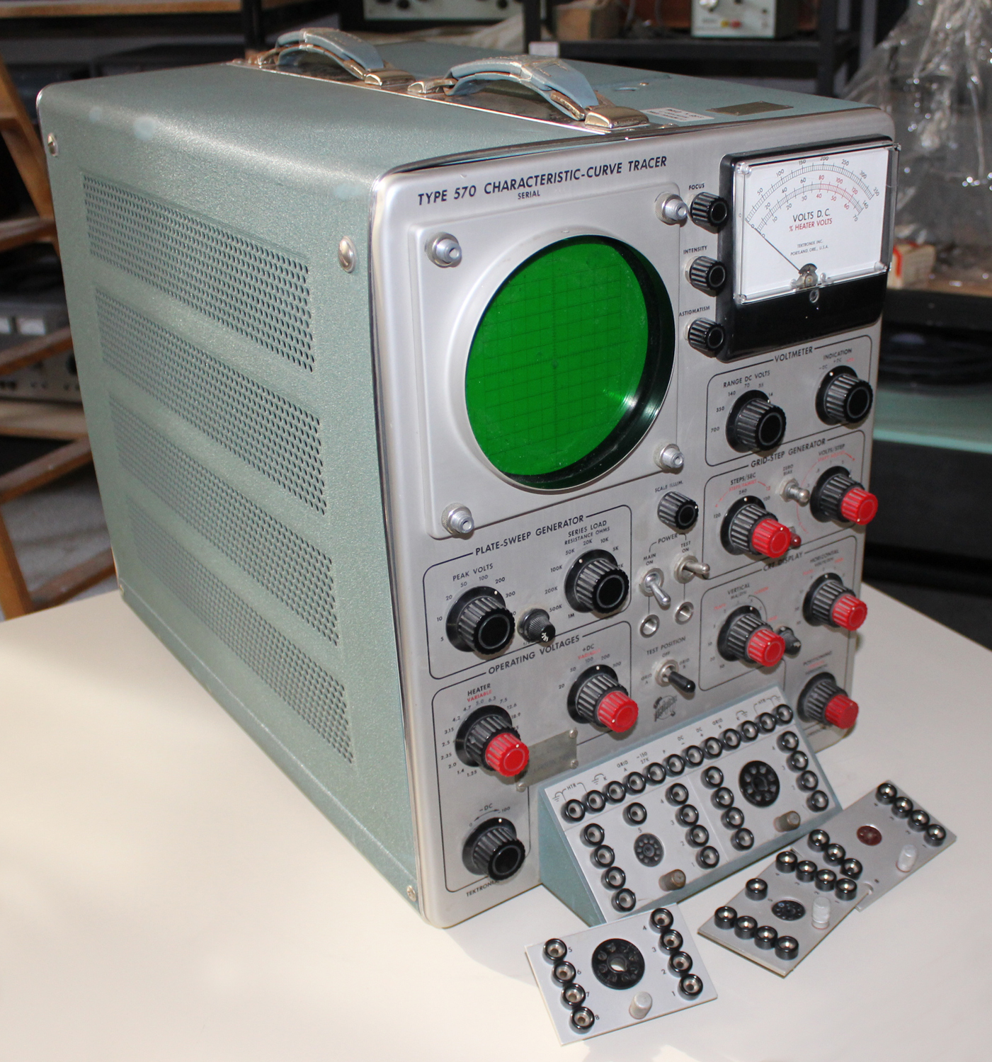
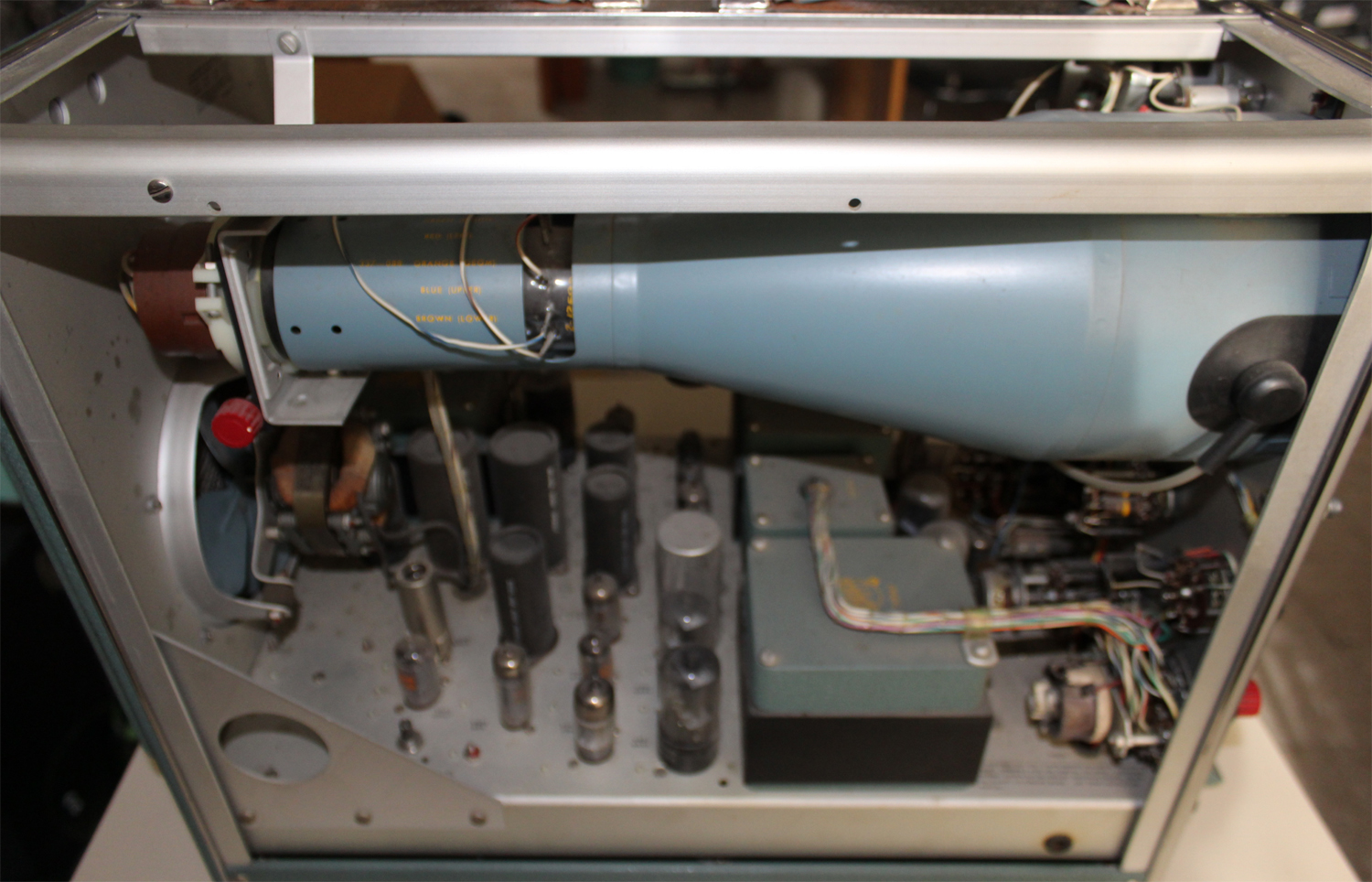
 Caracteristic-curve tracer type 570, serial number 5211, Tektronix Inc. Prima parte.
Dono della Fondazione Carlo e Giuseppe Piaggio, Genova.
Nell’Estratto dell’inventario del Laboratorio della Sezione Elettronica, in data giugno 1960 si fa corrispondere l’acquisto dell’oscilloscopio al numero D 1721 dell’inventario generale. Ma stranamente in quest’ultimo non si trova la solita corrispondenza, né c’è alcuna traccia dell’acquisto. Nell’Estratto si legge comunque: “Oscilloscopio modello 570 Tektronix”.
Nella Sezione Elettronica è conservato il manuale di istruzioni di cui riportiamo il testo diviso opportunamente in due parti. Inoltre pubblichiamo le pagine originali di MAINTENANCE nella seconda parte.
 §§§
§§§
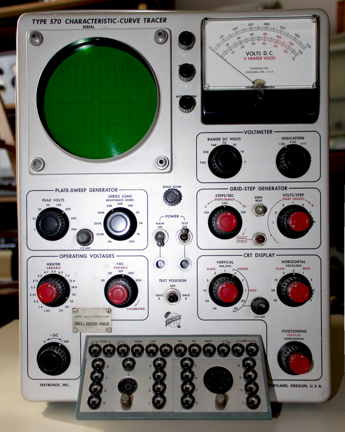
«SPECIFICATIONS
The Type 570 Characteristic-Curve Tracer presents a graphic analysis of vacuum-tube characteristics under a wide range of operating conditions. Calibrated horizontal and vertical deflection make it possible to measure the characteristics directly or the curves may be compared with preselected tube characteristics that have been reproduced on a mask over the cathode-ray tube. Front-panel switching between two test sockets permits rapid comparisons between two tubes or between two sections of the same tube.
Vertical Deflection Factor
Eleven steps from 0.02 ma/div. to 50 ma/div.
Accuracy: 3%
Horizontal Deflection Factor
Nine steps from .1 v/div. to 50 v/div.
Accuracy: 3%
Grid-Step Generator
Number of steps per family: 4- to 12.
Number of steps per second: 120 or 240.
Voltage change per step:
Seven positions from .1 to 10 volts/step.
Accuracy: 3%.
A single-family provision permits observation of tube characteristics under unusual conditions without danger of damage to the tube under test.
Maximum current: 50 ma average.
100 ma peak.
A 1/16 amp fuse protects the current measuring resistors in the .02 ma to 1 ma positions of the VERTICAL MA/DIV. switch.
Plate-Sweep Generator
Peak plate-sweep voltage;
Eight steps from 5 to 500 volts. Nominal voltages depending on line voltage.
Series load resistance:
Eleven steps from 300 ohms to 1 megaohm.
Accuracy: 300 ohms, 35%: 1 k and 2 k, 10%;
5 k to 1 meg. 5%.
Maximum current capability
1 amp peak.
.25 amp average.
A ½ amp fuse protects the plate-sweep generator. An additional 1/16 amp fuse is inserted to protect the current measuring circuits in the .02 ma to 1 ma positions of the VERTICAL MA/DIV. switch when measuring plate current.
Operating Voltages
Heater Voltages:
Seventeen steps from 1.25 volts to 117 volts, each step adjustable over a range of about ±20%.
Maximum Heater Power: 30 watts.
Positive DC Voltage:
Five calibrated steps from 20 to 300 volts, 3% accuracy.
Continuously variable, uncalibrated, from 10 to 300 volts.
Maximum Current From + DC Supply:
150 ma peak.
50 ma average.
Negative DC Voltage:
Continuously variable from U to -100 volts. Source impedance: 175 k.
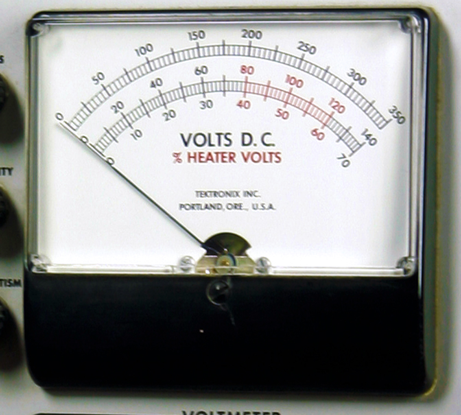
Voltmeter
Measures positive and negative operating voltages in seven ranges from 7 to 700 volts, full scale.
In the HTR position the meter shows the heater voltage as a percentage of the figure selected by the HEATER switch.
Other Features
Tube-Socket Switch:
The TEST POSITION switch selects either of two tubes or two halves of one tube.
Safety Switch:
The TEST POWER switch removes all potentially dangerous voltages from the patch panel for safety when connections are being changed.
Regulated Power Supplies:
All power supplies affecting calibration are regulated for load and line-voltage variations. The heater, negative dc, and plate-sweep voltages are unregulated.
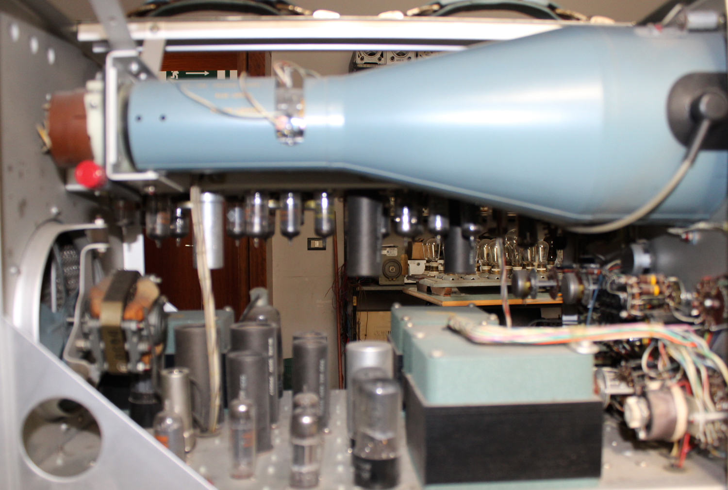
Cathode-Ray Tube:
Type: Tektronix T52P1
Other phosphors available.
Accelerating Potential: 4 kv.
Illuminated Graticule:
Edge lighted graticule provides either red or white illumination.
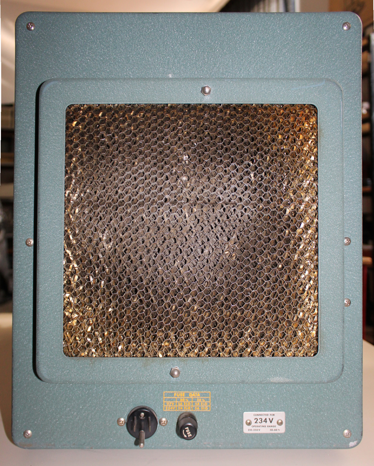
Mechanical Specifications
Ventilation: Filtered, forced air ventilation.
Construction: Aluminum alloy chassis and cabinet.
Finish: Photo-etched anodized panel, blue wrinkle cabinet.
Dimensions: 16½” high, 13” wide, 24½” deep.
Weight: 75 pounds.
Power Requirements: 105-125 or 210-250 v, 50-60 cycles, 300 to 500 watts at 117 or 234 volts.
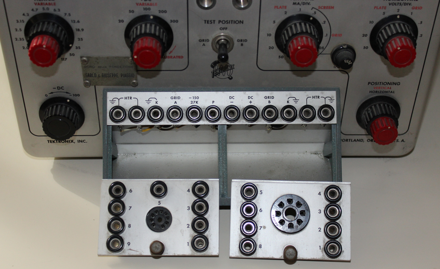
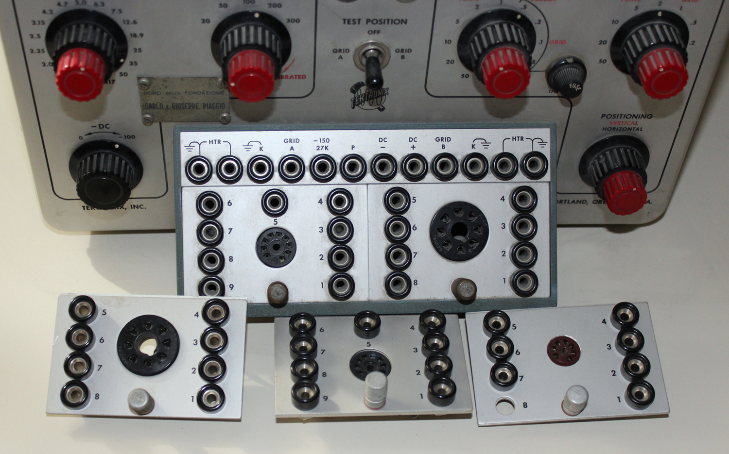
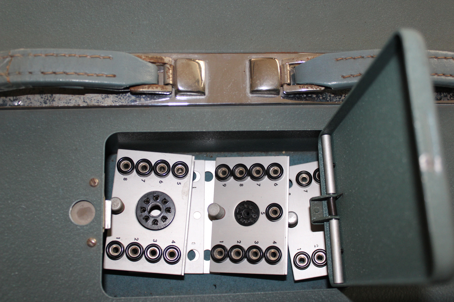
Accessories Included
2 octal-socket adapter plates
2 nine-pin miniature adapter plates
2 seven-pin miniature adapter plates
2 blank adapter plates
10 patch cords with plug and socket connectors;
5 red, 5 black
10 patch cords with plug connectors; 5 red, 5 black.
6 patch cords with parasitic oscillation suppression resistor;
2-100 ohm, 2-330 ohm, 2-1000 ohm.
1 6U8 vacuum tube
1 light filter
5 1/16 amp 3AG fuses
1 instruction manual
OPERATING INSTRUCTIONS
PRELIMINARY INSTRUCTIONS
CAUTION: High voltages can be present at the patch panel. The flexible operational setup facility of the Type requires that potentially dangerous voltages be available at the patch panel. Turn off the TEST POWER switch when making or changing connections. Practice safety by connecting each lead first to the adapter plate and then to the patch panel.
Note: Fuses are used to protect some of the circuits supplying power to the patch panel. Damage to other circuits is possible by extended periods of heavy overload. In no case is any provision made to protect the vacuum tube or other device being tested.
Cooling
The Type 570 Characteristic-Curve Tracer is cooled by filtered, forced-air ventilation. The instrument must therefore be placed so the air intake is not blocked, and the filter must be clean enough to permit adequate air circulation.
Illuminated Graticule
The adjustable graticule lighting control labeled SCALE ILLUM., can be adjusted to suit the lighting conditions of the room. The colored filter supplied gives maximum trace contrast in the presence of room light. This filter should normally be mounted next to the cathode-ray tube with the scribed graticule on the outside.
The graticule is scribed in ten equal divisions, horizontally and vertically. These scale markings and calibrated vertical and horizontal deflection sensitivities can be used to convert thebeam position into milliamps and volts. Vertical sensitivities are calibrated in milliamps per division and horizontal sensitivities in volts per division; which, if multiplied by divisions of deflection, give milliamps and volts.
The graticule can be mounted in either of twopositions rotated 180 degrees from each other. The graticule illumination is red in one position and white in the other. The white will reproduce well photographically.
50-Cycle Operation
This instrument is calibrated for a 60-cycle line frequency at the factory. For 50-cycle operation it will be necessary to readjust the step-generator phase controls. See “Step Generator Phase Adjustments” in the Maintenance Sectionof this manual.
234-Volt Operation
Unless it is tagged for 234-volt operation this instrument is connected for 117-volt operation.
For 234-volt operation it is necessary to change the jumpers on two transformers to connect the primary windings in series. An AC Wiring Diagram is included on the Main Power Supply diagram.
For 234-volt operation remove the jumpers between pins l and 2 and between 3 and 4 on T501. Connect a jumper between pins 2 and 3 on T501. Check to see that the fan is connected to pins 1 and 3. Remove the jumpers between pins 1 and 2 and between pins 3 and 4 on T401. Connect a jumper between pins 2 and 3 on T401.
Do not change the connections on the other transformers since these are still supplied with 117 volts. Change the fuse to a 3 amp, 3 AG Slo- Blo.
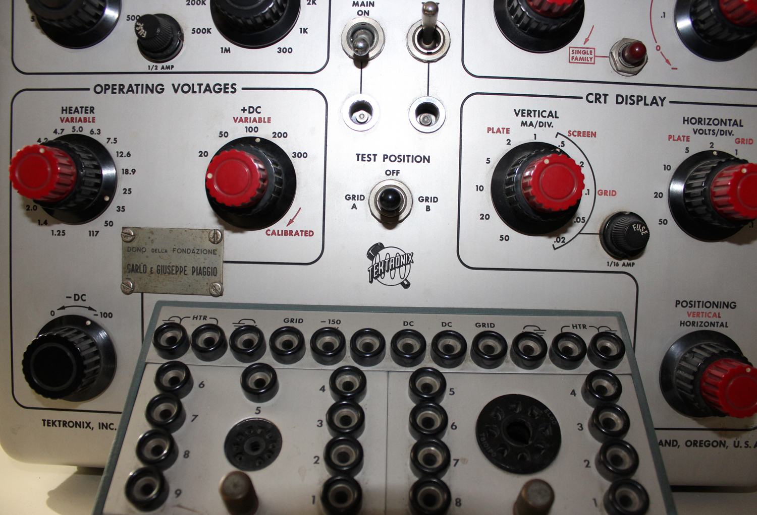
FUNCTIONS OF CONTROLS AND CONNECTORS
Plate-Sweep Generator
PEAK VOLTS Eight-position switch selects peak voltage from plate-sweep generator.
SERIES LOAD Eleven-position switch selects series load resistors for plate-sweep generator.
Operating voltage
HEATER Seventeen-position switch selects heater voltage for tube under test.
VARIABLE Variable resistor allows heater voltage to be raised or lowered about 20%.
+ DC Five-position switch selects screen voltage for tube under test. Voltages shown are correct only when red knob is fully clockwise.
VARIABLE (red knob) Variable resistor allows adjustment of +dc supply between voltages indicated on +DC switch. Knob must be fully clockwise for +DC switch to be calibrated.
-DC Variable resistor selects a portion of the voltage between ground and the negative 150 v supply for biasing purposes.
Voltmeter
RANGE DC VOLTS Seven-position switch selects voltmeter multiplier.
INDICATION Three-position switch connects voltmeter to -DC, +DC or heater supplies for the tube under test.
Grid-Step Generator
STEPS/SEC Three-position switch selects a stepping rate of either 120 or 240 steps per second. (100 or 200 steps per second at 50 cycle line frequency.) The two 120 positions allow grid-voltage stepping to occur at either end of the plate-voltage sweep.
STEPS/FAMILY
(red knob) Variable resistor adjusts step generator for from four to twelve steps thereby adjusting the number of curves plotted from four to twelve.
ZERO-BIAS Push-to-operate switch connects grid of tube under test to ground to plot a zero bias curve.
VOLTS/STEP Seven-position switch adjusts the amplitude of the steps from the step generator.
START ADJUST Variable resistor adjusts the dc level of the stair-step waveform thus permitting the first step to be positive or negative or at zero bias.
SINGLE FAMILY Push-to-operate switch, effective only when the STEPS/FAMILY control is clockwise, displays a single family of curves after which the grid is held negative.
CRT Display
VERTICAL MA/DIV Eleven-position switch selects vertical sensitivity.
Vertical Display Selector Three-position switch selects the plate, screen or grid voltage for display on the vertical axis.
HORIZONTAL VOLTS/DIV Nine-position switch selects horizontal sensitivity.
Horizontal Display Selector Two-position switch selects the grid or plate voltage of the tube under test for display on the horizontal axis.
POSITIONING
(red knob) Variable control adjusts position of display along vertical axis.
(black knob) Variable control adjusts position of display along horizontal axis.
Miscellaneous
TEST POSITION Three-position lever-type switch selects either of two tubes which may be under test or removes grid waveform in center position.
POWER MAIN On-off switch in primary of power transformer and ventilating fan lead.
TEST On-off switch removes all voltages from patch panel.
Top Recessed Panel
FOCUS Control to adjust the focus of the cathode-ray tube beam.
INTENSITY Control to vary the brightness of the crt display.
ASTIGMATISM Control to adjust the beam focus in conjunction with the FOCUS control.
SCALE ILLUM Variable resistor to adjust the brightness of the graticule lights.
PLATE SWEEP FUSE Fuse to protect the plate-sweep generator circuits.
VERT. ATTEN. CIR. FUSE Fuse to protect the resistors in the high sensitivity ranges of the MA/DIV. attenuator.
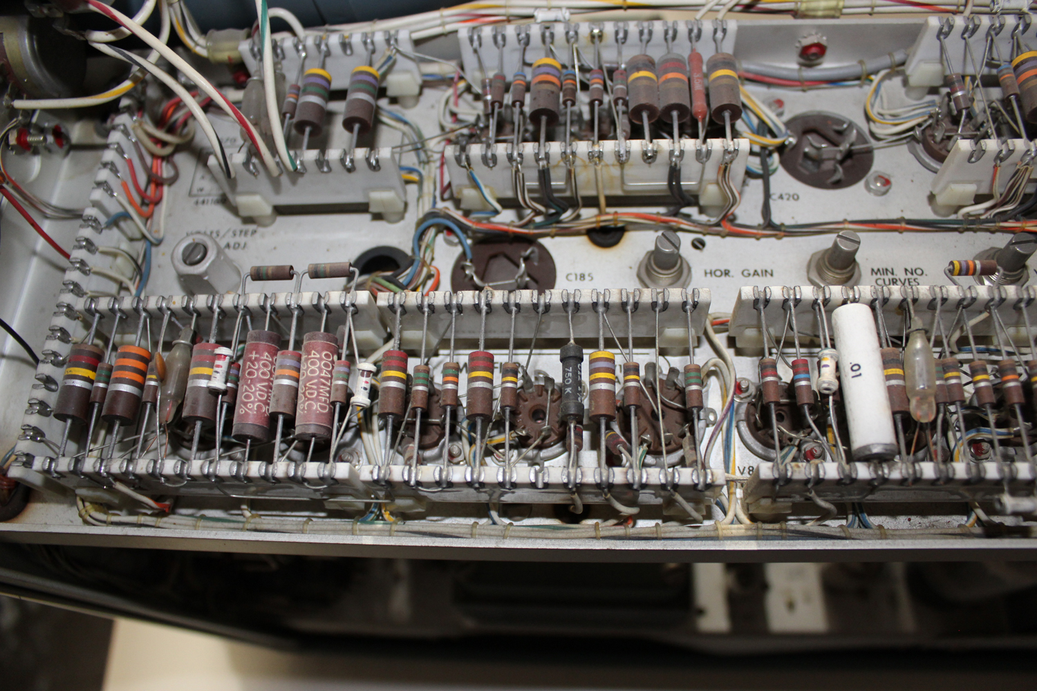
VOLTS/STEP ZERO ADJUST Screwdriver adjustment to balance the step amplifier to prevent a shift of the zero-bias step as the VOLTS/STEP control is rotated.
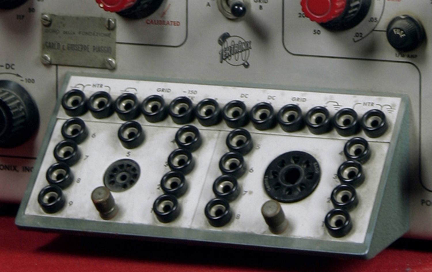
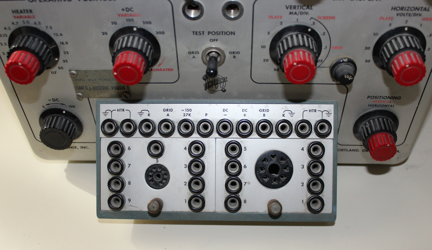
Patch Panel
HTR Two paralleled sets of jacks connected to the heater transformer.
K Two grounded jacks for the cathode connections.
GRID A Jack which is connected to the grid-step voltage when the TEST POSITION switch is in the GRID A position. Jack is returned to -300 volts through a 10 megohm resistor in the other positions of the switch.
GRID B Jack which is connected to the grid-step voltage when the TEST POSITION switch is in the GRID B position. Other characteristics as for GRID A.
-150,27 k Jack connected to the regulated -150 v supply through a 27 k isolation resistor.
P Jack connected to output of the plate-sweep generator via the series load resistor selected by the SERIES LOAD switch.
– DC Jack connected to the -DC potentiometer providing a negative bias voltage with a source resistance of about 175 k.
+ DC Jack connected to the regulated, variable +DC supply.
FIRST-TIME OPERATION
This section describes in detail the procedure for setting up a typical display of the plate-characteristic curve for a triode and a pentode. A type 6U8 triode-pentode is specified. If a different tube type is used the patch-panel connections should be changed as required. Except for the heater voltage, these settings can serve as the starting point for checking most receiving-type tubes. The settings may then be altered as required to obtain a useful presentation.
Control Settings
1.Turn the POWER switches to OFF.
2.Connect the power cord to a source of 117-volt, 60-cycle power.
3.Turn the MAIN POWER switch to ON.
4.Set the controls as follows:
Top Recessed Panel
INTENSITY Center
FOCUS Center
ASTIGMATISM Center
Plate-Sweep Generator
PEAK VOLTS 200
SERIES LOAD 10 K
Operating Voltages
HEATER 6.3
VARIABLE Center
+DC 100
VARIABLE Clockwise
Voltmeter
INDICATION HTR
Grid-Step Generator
STEPS/FAMILY Center
STEPS/SEC 240
START ADJUST Counterclockwise
VOLTS/STEP .5
CRT Display
VERTICAL MA/DIV 1
PLATE-SCREEN-GRID PLATE
HORIZONTAL VOLTS/DIV 20
PLATE-GRID PLATE
POSITIONING Controls Centered
5.Insert a nine-pin-miniature socket adapter.
6.Connect the patch cords as follows for a type 6U8 vacuum tube:
a.Pin 1 to P, the triode plate to the plate sweep.
b.Pin 2 to GRID B, the pentode grid to the “B” grid connector.
c.Pin 3 to +DC, the pentode screen to the +DC supply.
d.Pins 4 and 5 to a pair of HTR jacks.
e.Pin 6 to P, the pentode plate to the plate sweep.
f.Pin 7 to K, the pentode cathode and suppressor to ground.
g.Pin B to K, the triode cathode to ground.
h.Pin 9 to GRID A, the triode grid to the “A” grid connector.
7.Plug a type 6US vacuum tube in the socket.
8.Turn the TEST POWER switch to ON.
9.Adjust the VARIABLE heater control to obtain a reading of 100% on the voltmeter.
10.Move the TEST POSITION switch to GRID A.
11.Adjust the positioning controls so the curves start in the lower, left-hand corner of the graticule.
12.Adjust the FOCUS, ASTIGMATISM, and INTENSITY controls for a sharp trace of comfortable brightness.
13.Press the ZERO BIAS button and upon releasing it set the START ADJUST control so that the uppermost curve corresponds with the zero-bias curve. You are now displaying the 6U8 triode plate-characteristic curve. Move the STEPS/SEC control to each of the 120 positions and note that the grid-step generator switches at only one end of the sweep in each of these positions.
Now move the TEST POSITION switch to GRID B. You are now displaying the 6U8 pentode plate-characteristic curve. Move the red knob, concentric with the VERTICAL MA/DIV control, to SCREEN. This is screen current plotted against plate voltage. Return the controls to plot the triode curve.
Now move the PEAK VOLTS control down three positions to 20, the VERTICAL MA/DIV three positions to .1 and the HORIZONTAL VOLTS/DIV three positions to 2. This is an expanded display of lower left corner of the first triode characteristic curve.
You will notice that the curves are not plotted all the way to the origin and that the curves intersect the current axis above the origin. These are normal effects and do not indicate miscalibration of the instrument. The correct horizontal positioning can be determined by momentarily grounding the plate connector, P. The line which results should lie along the current axis.
The initial velocity of the emitted electrons causes plate current to flow at zero plate voltage as indicated by the curves intersecting the current axis above the origin. This effect is more pronounced with increased series load resistance. A similar effect in the plate-sweep-generator rectifiers prevents the plate-sweep voltage from dropping completely to zero.
THERMIONIC DIODE CURVES
To plot diode curves, connect the diode in the normal manner with the cathode to ground, K, and the plate to the plate-sweep generator, P. Set the CRT DISPLAY controls to read plate current and plate voltage. Before turning the TEST POWER switch on, set the PEAK VOLTS control to a low voltage. After the TEST POWER switch is turned on, wait until the cathode of the tube under test has reached operating temperature before raising the plate-sweep voltage. The plate-sweep voltage can then be raised until maximum operating conditions are reached.
It is sometimes of interest to sweep the plate voltage negative with respect to the cathode, beyond the point of plate-current cutoff. This can be done by connecting a battery between the cathode and ground to raise the cathode positive. Three volts is normally sufficient. The +DC supply can be used instead of a battery if the peak plate current is to be less than 50 ma.
To use the +DC supply, connect the cathode of the tube under test to +DC. Set the +DC controls to minimum, about ten volts. Connect a 200 ohm, 2 watt resistor from the cathode to ground to keep the power supply in regulation. The curve can now be plotted in the normal manner. The zero voltage point can be determined by momentarily connecting the plate to the cathode. Be sure there is sufficient series resistance in the plate-sweep generator to limit the current to a safe value when you do this. Position the line which you obtain behind a graticule line. This line will then be the vertical axis.
TRIODE CURVES
By setting the CRT DISPLAY controls to the proper positions the following curves can be plotted: plate current-plate voltage, grid current-plate voltage, plate current-grid voltage, and grid current-grid voltage.
Grid-Step Waveform
Triode curves involve the use of the grid-step generator in addition to the circuits used in plotting diode curves. The grid-step wave form is a stair-step waveform starting at zero or some positive voltage and going negative for from four to twelve steps. It can be set to have as many as eight positive steps. The position of the zero-bias curve can be determined by pushing the ZERO BIAS button.
The STEPS/SEC control provides a means of selecting the stepping point of the step generator. In the right hand position, labeled 120, the generator steps while the plate voltage is at maximum and in the left hand position the generator steps when the plate voltage is at a minimum. In the 240 position, stepping occurs at both maximum and minimum voltage points, and the faster switching rate reduces flicker.
If either end of the plate sweep is particularly important, it is usually better to set the step generator to switch at the opposite end. However, in some cases where no error is introduced, the switching lines help to plot a continuous curve between steps.
Plate Current-Plate Voltage
To display plate current-plate voltage curves the tube to be tested is connected in the normal manner with the cathode to ground, K, the grid
to GRID A, or B and the plate to P. Turn the vertical-and horizontal-display-selector controls to PLATE.
The following control settings should be checked when a particular tube type is being tested the first time:
1.Set the HEATER control to the correct voltage.
2.Set the step generator START ADJUST control nearly counterclockwise to avoid a positive grid voltage.
3.Set the plate-sweep generator PEAK VOLTS control for a safe Peak voltage.
4.If high plate current is expected, set the VERTICAL MA/DIV control nearly counterclockwise to protect the small, low-current measuring resistors.
The other controls can be set after the TEST POWER switch is turned on and the tube cathode has come up to operating temperature. Once the desired settings have been obtained for a given tube type, other tubes of the same type can be inserted without resetting the controls.
Grid Current-Plate Voltage
Grid current can be plotted against plate voltage by setting the controls as for the plate current-plate voltage display and moving the vertical display selector to GRID. Increase the vertical sensitivity as required. Normally the grid current will not be measurable until the grid approaches zero bias or goes positive.
Plate Current-Grid Voltage
To display plate current plotted against grid voltage, set the controls as for the plate current-plate voltage curves and switch the horizontal display selector to GRID. This automatically positions the display to the right. It will normally be necessary to increase the horizontal sensitivity and reposition the display slightly.
The display obtained consists of vertical lines which show the variation of plate current as the plate is swept from zero to maximum voltage. The part of the curve of primary interest is formed by the tops of these lines. This is the dynamic characteristic for the combined tube and load resistance. However, if the SERIES LOAD is set to 300 the effect of the load resistance is very slight.
The voltage from the plate-sweep generator depends upon the line voltage and it is not intended that the calibration of the PEAK VOLTS control be exact. If the actual peak plate voltage is desired, switch the horizontal display selector to PLATE and read the peak voltage from the screen.
A method of plotting a more conventional-looking transfer characteristic is to connect the plate to the +DC supply. If the vertical display selector is turned to SCREEN the plate current will be plotted. The advantages of this connection are that the vertical lines are not displayed and the plate voltage is continuously variable and indicated by the voltmeter. Disadvantages are that the maximum current and voltage capability of the +DC supply is less than that of the plate-sweep generator, and the continuous voltage applied to the tube under test increases the average plate dissipation in this tube.
Grid Current-Grid Voltage
After displaying plate current-grid voltage curves the grid current-grid voltage display can be obtained by switching the vertical display selector to GRID. Increased vertical sensitivity may be required. The vertical lines can be eliminated by connecting the plate to the +DC connector as for the transfer characteristic.
Tube Switching
Two tubes or two sections of one tube can be connected at once for comparison purposes or to speed testing. The grid of one tube should be connected to GRID A and the other to GRID B. Both plates should be connected to the plate-sweep generator at P. The tube to be tested is now selected by the TEST POSITION switch. The other tube is held cut off by a 10 megohm resistor connected to -300 volts. Occasionally a defective tube will still conduct under these conditions, causing an error in the presentation. If you suspect that this is occurring, switch the TEST POSITION switch to OFF. This connects the grids of both tubes to the 10 megohm resistor and there should be no indication of plate current on the screen.
PENTODE CURVES
In addition to the curves which can be plotted for a triode, pentode screen current can be plotted against either plate or control-grid voltage. The pentode curves are plotted in the same manner as the triode curves with the +DC supply used for screen voltage. This prevents the alternate connection mentioned in the triode section under Plate Current-Grid Voltage in which the +DC supply is used as the plate supply.
Screen Current-Plate Voltage
This curve can be plotted by setting the controls as for the plate current-plate voltage display with the exception that the vertical display selector is set to SCREEN. If switching lines interfere with the display at the left, the STEPS/SEC control should be moved to the right hand 120 position.
Screen Current-Grid Voltage
This curve is similar to the plate current-grid voltage curve. It is obtained by setting the vertical display selector to SCREEN and the horizontal display selector to GRID. Adjust the HORIZONTAL VOLTS/DIV as required to obtain a full screen display and position the display as desired. If the STEPS/SEC control is set to the right hand position the switching lines will form a continuous curve indicating the screen current at maximum plate voltage as set by the PEAK VOLTS control. The vertical lines represent the variation of screen current as the plate voltage
is swept from zero to maximum».
§§§
Per consultare la seconda parte scrivere “570” su Cerca.
Foto di Claudio Profumieri e di Daniele Maiani. Elaborazioni, ricerche e testo a cura di Fabio Panfili.
Per ingrandire le immagini cliccare su di esse col tasto destro del mouse e scegliere tra le opzioni.