 Transformer FERRANTI ENGLAND type AF3. Seconda parte.
Le istruzioni, del settembre del 1929, si compongono di 6 pagine con tutte le caratteristiche peculiari dell`oggetto e sono riportate in fondo alla scheda.
I puntini (…) sottolineano gli omissis.
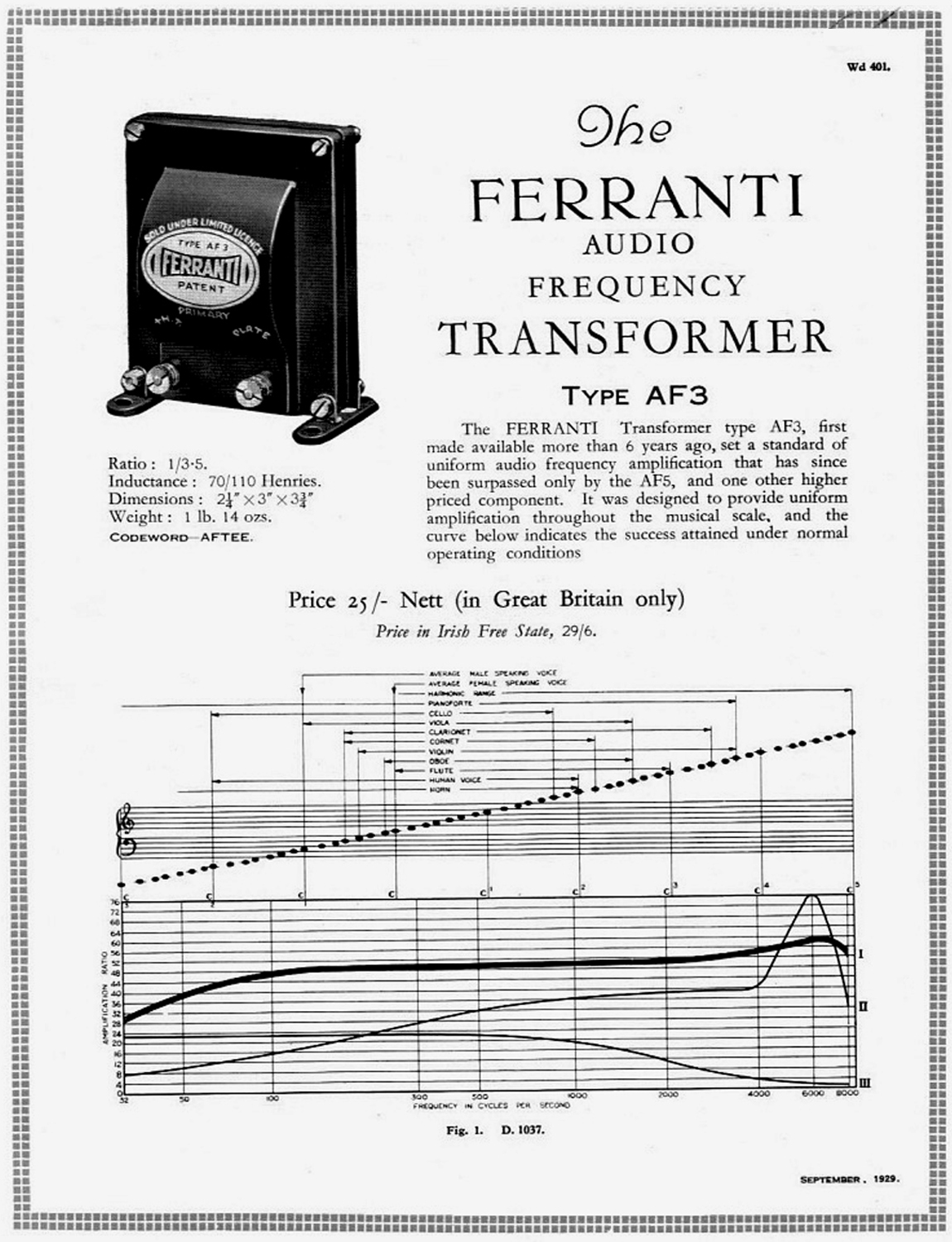
« Ratio 1/3-5. Inductance: 70/110 Henryes. Dimensions: 2 1/4 ” × 3″ × 3 3/4″. Weight: 1 lb. 14 ozs.
The FERRANTI AUDIO FREQUENCY TRANSFORMER TYPE AF3.
The FERRANTI Transformer type AF3, first made available more than 6 years ago, set standard of uniform audio frequency amplification that has since been surpassed only by the AF5, and one other higher priced component.
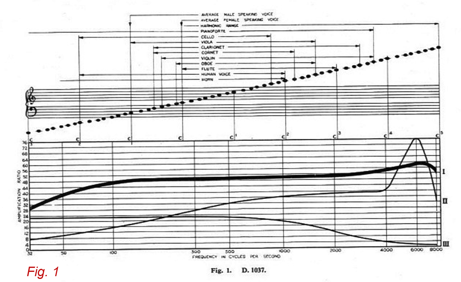
It was designed to provide uniform amplification throughout the musical scale, and the curve below (Fig. 1) indicates the success attained under normal operating conditions.
The above curves are obtained when using the respective components under their normal working conditions, each being followed by a power valve with a non-inductive load in the anode circuit.
The following are the conditions relating to each curve: Curve 1. – The FERRANTI AF3 Transformer following a 10,000 ohm valve having an amplification factor of 14. H.T. 100 volts. Milliamps 3-5. Grid Bias 1-5 volts. Filaments 4 volts. Curve 2.- A modern Cheap Transformer used under similar conditions. Curve 3.- Resistance Capacity using high amplification couplings. »….
«AMPLIFICATION AND WHAT IT MEANS …. The curve [our Fig. 1] shows the amplification provided by the Ferranti AF3 Transformer when used following a valve having a working impedance of approximately 10,000 ohms.
It will be seen that the amplification is remarkably even between 100 and 8,000 cycles, the slightly rising charateristic at the higher frequencies being advantage tending to compensate for the loss of these frequencies due to tuning, interwiring, and other stray capacities in Receivers.
At a frequency as low as 50 cycles (more than two octaves below middle C) the cut-off is only 20% a figure better than that given by any other Transformer available at the same pitch. …
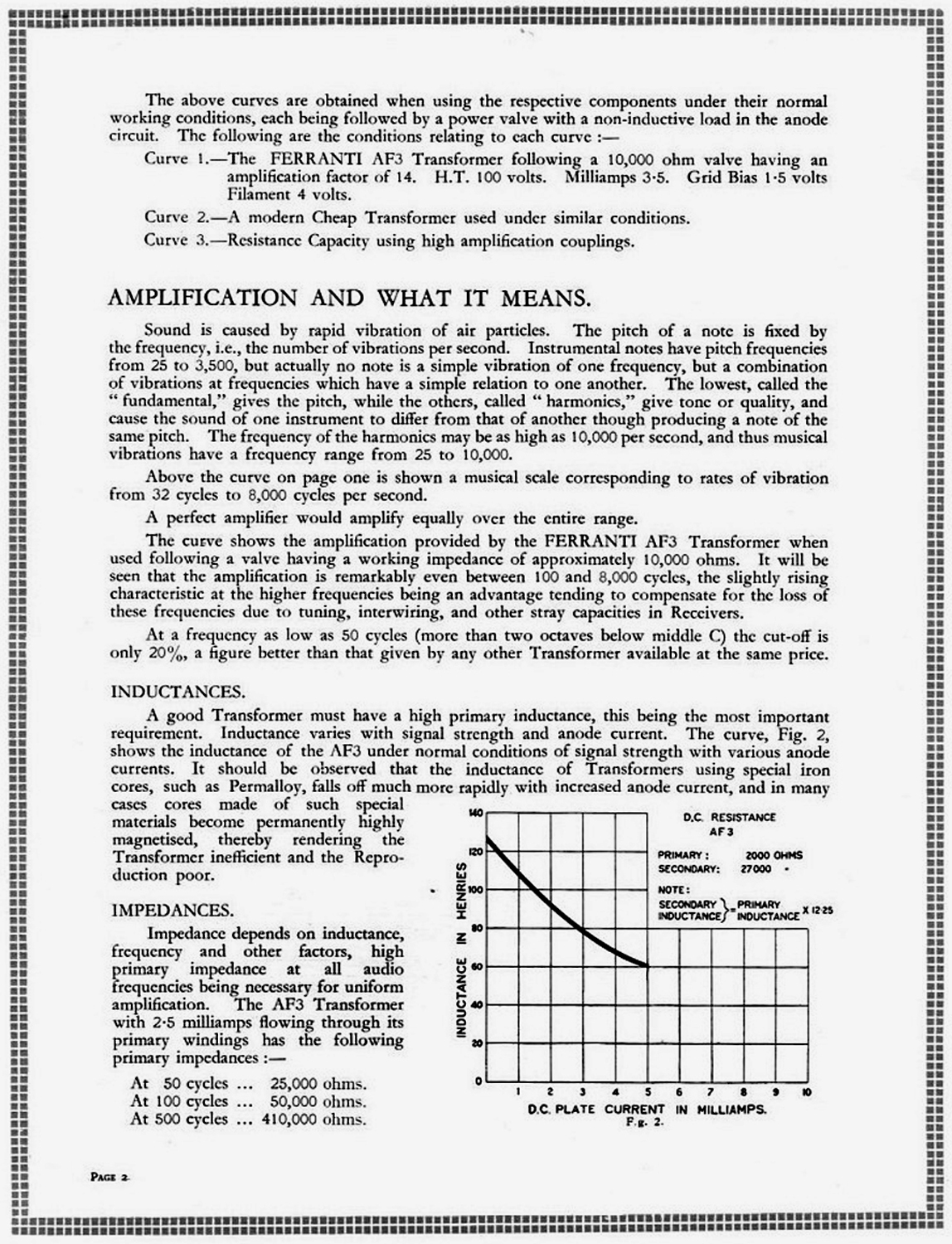
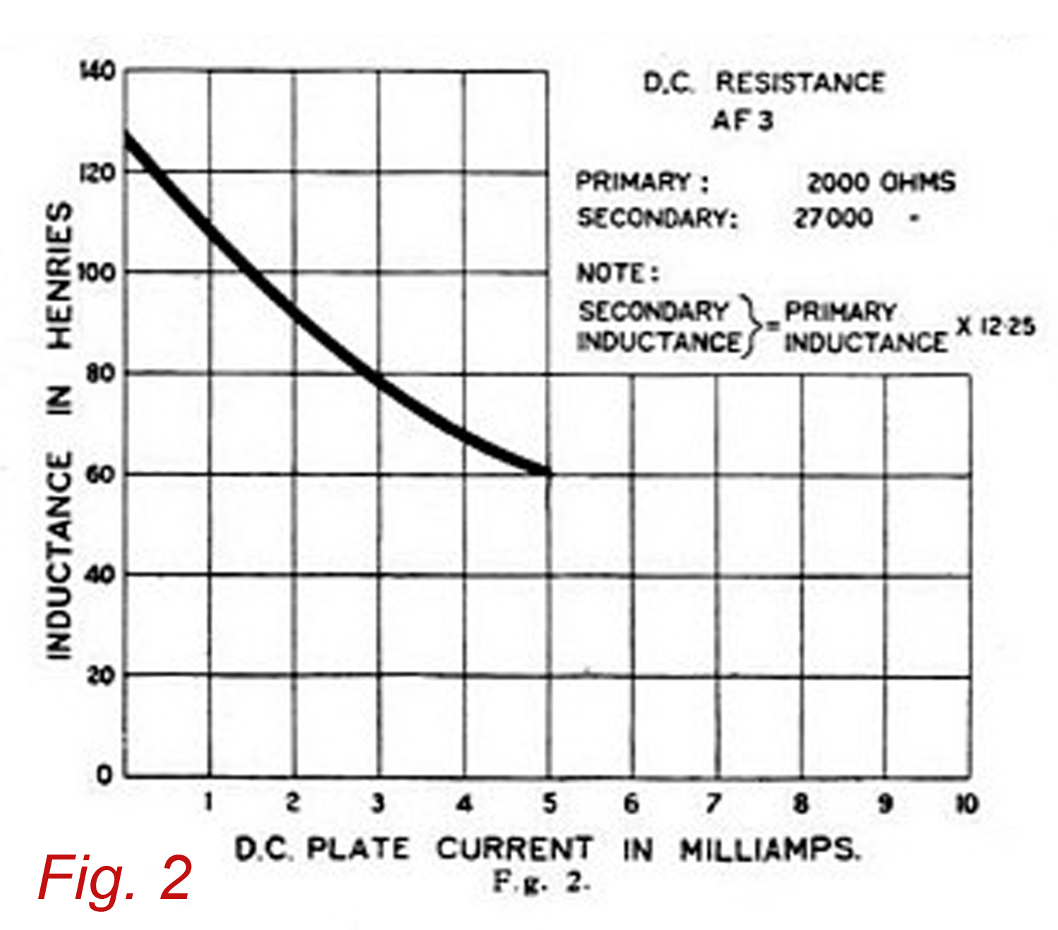
INDUCTANCES. … A good Transformer must have a high primary inductance, this being the most important requirement. Inductance varies with signal strength and anode current. The curve, Fig . 2, shows the inductance of the AF3 under normal conditions of signal strength with
various anode currents. It should be observed that the inductance of Transformers using special iron cores, such a Permalloy, falls off much more rapidly with increased anode current, and in many cases cores made of such special materials become permanently highly magnetised, thereby rendering the Transformer inefficient and the Reproduction poor.
IMPEDANCES. Impedance depends on inductance, frequency and other factors, high primary impedance at all audio frequencies being necessary for uniform amplification. The AF3 Transformer whith 2-5 milliamps flowing through its primary windings has the following primary impedances: – At 50 cycles 25,000 ohms. At 100 cycles 50,000 ohms. At 500 cycles 410,000 ohms. With lower milliamps the impedance are greater. The valve preceding the AF3 with suitable H.T. and grid bias should not take more than 5 milliamps. Larger anode currents will not damage the Transformer but will so reduce its inductance that the value of the large amount of expensive material put into the Transformer is lost. It should be noted that in a properly designed Amplifier it is unnecessary to employ a valve taking more than 5 milliamps before any Audio Frequency Transformer. …
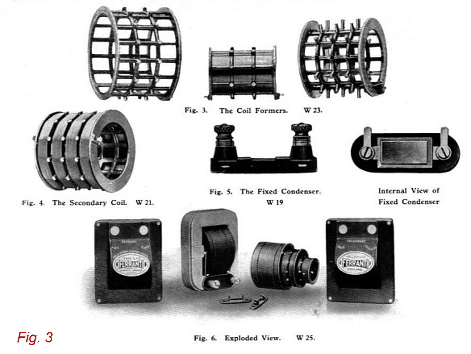
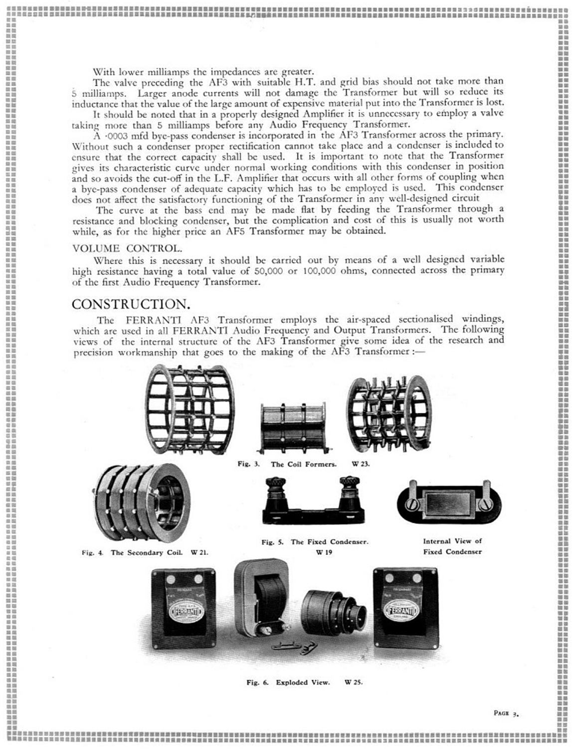
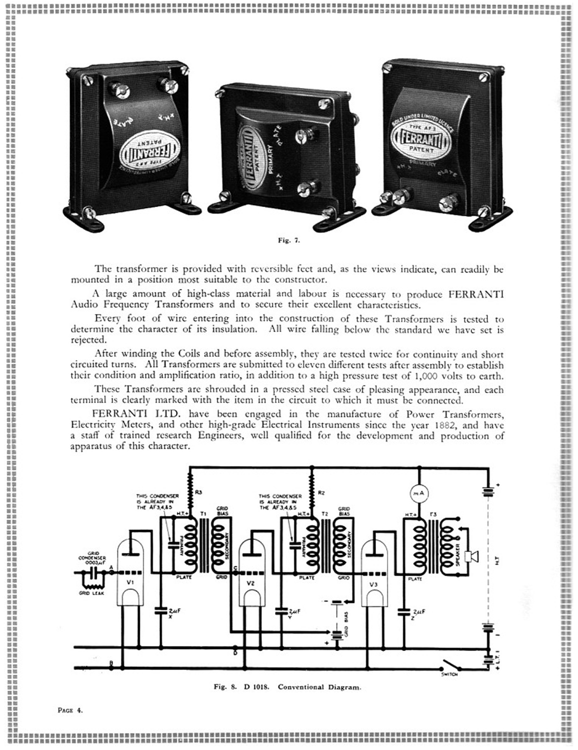
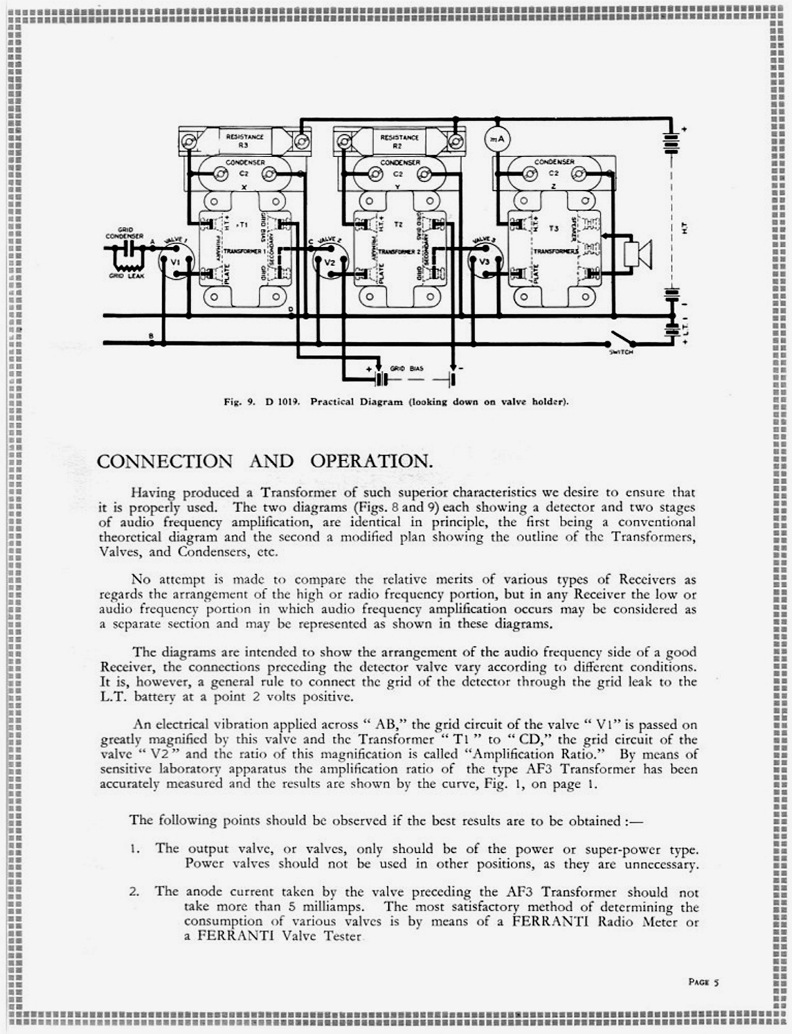
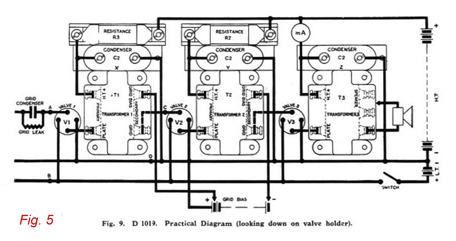
CONSTRUCTION. The FERRANTI AF3 Transformer employs the air-spaced sectionalised windings, which are used in all Ferranti Audio Frequency an Output Transformers. The following views [our Fig. 2] of the internal structure of the AF3 Transformer give some idea of the research and precision workmanship that goes to the making of the AF3 Transformer… CONNECTION AND OPERATION. The two diagrams (Figs. 8 and 9) [ see our Fig. 4 and Fig. 5] each showing a detector and two stages of audio frequency amplification, are identical in principle, the first being a conventional theoretical diagram and the second a modified plan showing the outline of the Transformers, Valves, and Condensers, etc. … The diagrams are intended to show the arrangement of the audio frequency side of a good Receiver, the connections preceding the detector valve vary according to different conditions. It is, however, a general rule to connect the grid of the detector through the grid leak to the L.T. battery at a point 2 volts positive. …».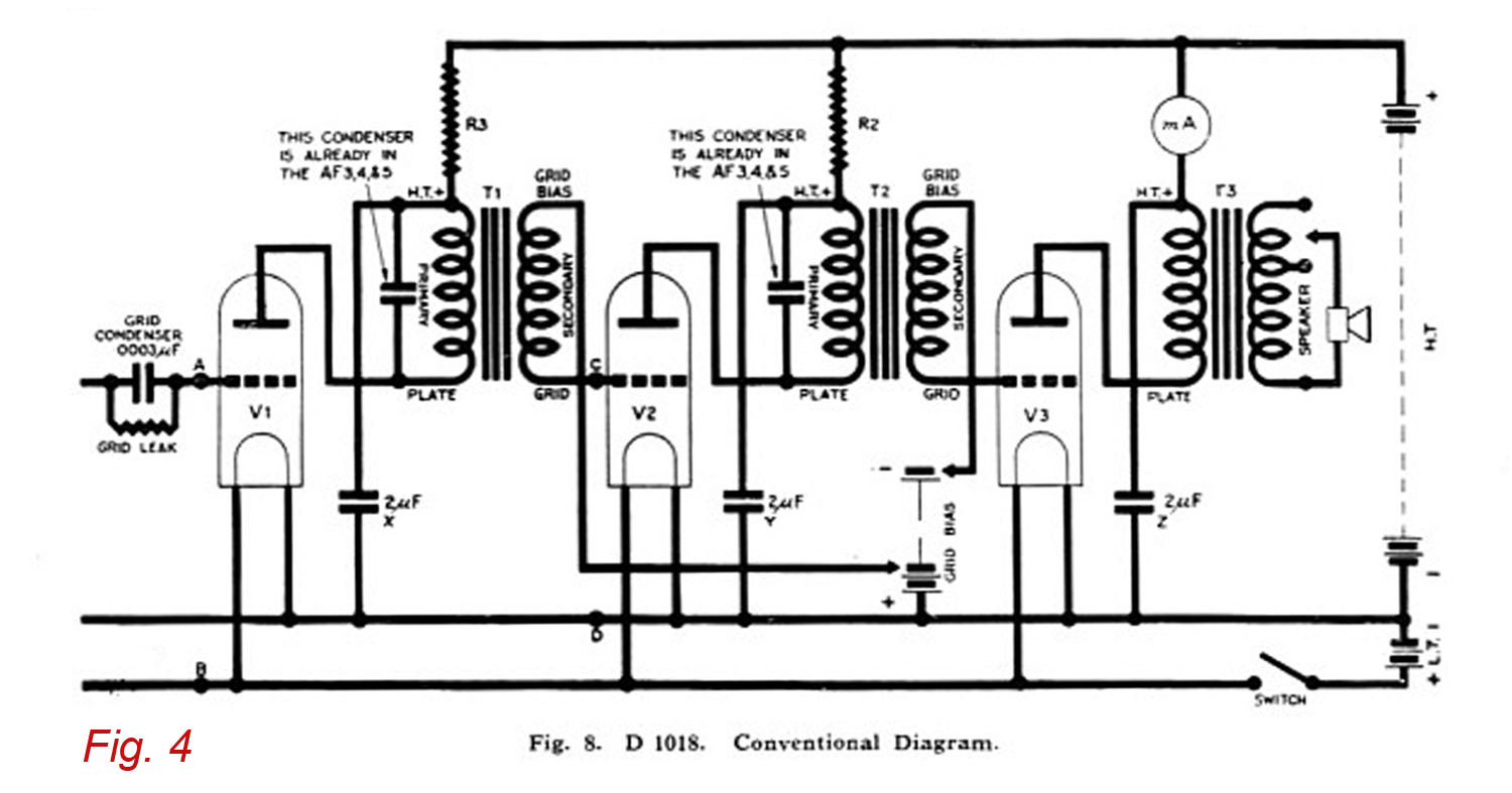
Per consultare la prima parte scrivere “Ferranti” su Cerca.
Foto di Claudio Profumieri. Elaborazioni, ricerche e testo a cura di Fabio Panfili.
Per ingrandire le immagini cliccare su di esse col tasto destro del mouse e scegliere tra le opzioni.